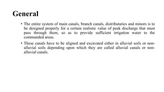
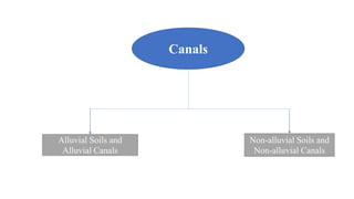
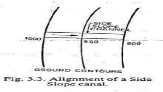
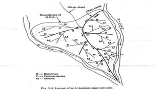
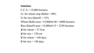
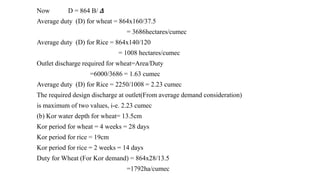
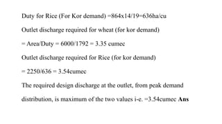
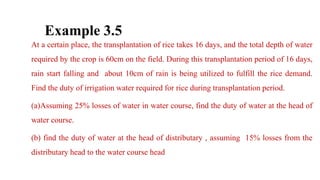
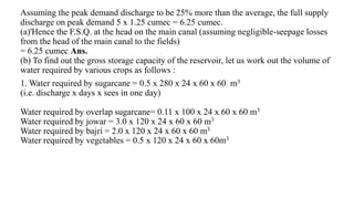
This chapter discusses irrigation structures at the head of canals, known as diversion head works. The objectives of diversion head works are to raise water levels, form storage areas, control silt and water level fluctuations. The key components discussed are weirs, barrages, under-sluices, divide walls, river training works like guide banks and spurs/groynes, fish ladders, and silt regulation works. Weirs are distinguished from barrages based on how ponding is achieved. Typical layouts of head works and structures like concrete, masonry and rock-fill weirs are presented.
Diversion head works are structures constructed across rivers to raise the water level upstream and divert water into canals. They include components like a weir, under sluices, fish ladders, divide walls, and canal head regulators. An ideal site has good foundations, allows the weir to be aligned perpendicular to flow, and has space for components while minimizing costs and environmental impacts. Weirs can be vertical drop, rock fill, or concrete, and are classified as storage, pick up, diversion, or waste based on their use and function. Diversion weirs divert river water into canals at a 90 degree angle to flow.
Canals are classified into different types based on factors which are as follows :
Based on the nature of the supply source
Based on functions
Based on the type of boundary surface soil
Based on the financial output
Based on discharge
Based on canal alignment
Structures placed in channels can control or measure water flow. Common structures include weirs and orifices. Weirs have a crest over which water flows. As head increases, flow increases dramatically for weirs. Sharp-crested weirs come in triangular, rectangular, and trapezoidal shapes. Broad-crested weirs support flow longitudinally. Orifices are openings where flow occurs. At low heads, orifices can act as weirs. Pipes also control flow as head loss from entrance, bends, and friction must be considered. Multiple flow regimes like weir, orifice, and full pipe flow apply for drop inlet spillways depending on head. Rockfill outlets provide energy dissipation
Cross section of the canal, balancing depth and canal fslAditya Mistry
1) The document discusses the cross section of irrigation canals, including configurations for cutting, filling, and partial cutting/filling. It describes the main components of a canal cross section such as side slopes, berms, and banks.
2) Balancing depth is defined as the depth of cutting where the quantity of excavated earth equals the amount required to form the canal banks, resulting in the most economical cross section.
3) Canal FSL (Full Supply Level) refers to the normal maximum operating water level of a canal when not affected by floods, corresponding to 100% capacity.
This document discusses different types of canal falls, which are structures constructed to lower the bed level of a canal. It describes seven common types of falls: ogee fall, rapid fall, trapezoidal fall, stepped fall, montague fall, vertical drop fall, and straight glacis fall. Each type is suitable for different conditions depending on factors like the height of fall, discharge, site topography, and cost. The document provides details on the design and suitability of each type of canal fall.
This document provides guidelines for designing irrigation channels, including:
1. Typical canal cross-sections, side slopes, berms, freeboard, banks, and other design elements are described.
2. Methods for calculating balancing depth to minimize earthworks and borrow pits are outlined.
3. The design procedure is demonstrated through an example that involves plotting longitudinal sections, calculating discharges and losses, and using Garret's diagram to determine channel dimensions.
Canal design involves defining types of canals based on use and discharge. There are two main types - aqueducts for water supply and navigable waterways. Canals are also classified based on discharge into main, branch, major/minor distributaries and watercourses. Design considers canal shape, lining requirements, and layout to minimize curves and balance cuts and fills. Proper drainage systems including surface ditches and subsurface pipes are also important to control water levels and allow cultivation. Explicit equations have been developed for least-cost design of common canal shapes like triangular, rectangular, trapezoidal and circular.
Cross drainage works (CDWs) are structures constructed where canals intersect natural drainages like rivers or streams. There are three main types of CDWs depending on the relative bed levels: 1) aqueducts or siphon aqueducts where the canal passes over the drainage, 2) super passages or siphon super passages where the drainage passes over the canal, and 3) level crossings where the canal and drainage intersect at the same level. The appropriate type of CDW is selected based on factors like relative bed levels, availability of suitable foundation, economic considerations, and discharge of the drainage. Key steps in planning CDWs include selecting a suitable site where the drainage crosses the canal alignment at a right angle and on
Reservoirs are artificial lakes or dams used to store water. They are created through dam construction in river valleys or excavation. Reservoirs store water for uses like irrigation, drinking water, hydroelectric power, and flood control. The storage capacity and zones of a reservoir, including dead storage, conservation, and flood control zones, determine how much water can be supplied over time periods ranging from daily to yearly. Hydrological investigations study runoff patterns and flood risks to inform reservoir planning and design.
Infrastructure for water resource development_ Sushil Kumar (NWA)_2011India Water Portal
Dams are classified based on their use, material, and size. The three main types are storage dams, diversion dams, and hydroelectric dams. Storage dams create reservoirs and are the most common type for water storage. Diversion dams raise water levels to divert water into conveyance systems. Infrastructure for water resources includes dams, barrages, weirs, canals, canal regulation works, and cross drainage works. Hydroelectric power plants have components like intake structures, penstocks, power houses with turbines, and tailraces.
This document provides an introduction to irrigation engineering. It discusses the necessity of irrigation in India due to variable rainfall and the need to maximize crop production. The advantages of irrigation include increased food production, optimal crop benefits, and generation of hydroelectric power. However, disadvantages can include water pollution, rising water tables, and waterlogging from over-irrigation. The document also outlines different types of irrigation like surface, flood, and lift irrigation. It describes techniques used in India for water distribution to farms, such as free flooding, border flooding, check flooding and drip irrigation.
Regulation works are structures constructed to regulate water flow in canals. The main types are head regulators, cross regulators, canal escapes, and canal outlets. Head regulators control water entry into off-taking channels from parent channels. Cross regulators are located downstream of off-takes and help control water levels and closures for repairs. Canal outlets connect distribution channels to field channels and supply water to irrigation fields at regulated discharges.
A weir is a solid structure built across a river to raise the water level and divert water into canals. There are different types of weirs including masonry weirs with vertical drops, rock fill weirs with sloping aprons, and concrete weirs with downstream slopes. Weirs can fail due to subsurface piping, uplift pressure, surface water suction or scouring. Remedies include installing sheet piles and ensuring sufficient floor thickness and length. A barrage is similar to a weir but uses gates rather than a solid structure to control water levels. Barrages are more expensive than weirs but allow better control of water levels and less silting during floods by raising the gates.
Canals are human-made waterways that allow boats and ships to pass between bodies of water. They are also used to transport water for irrigation and other human uses. Canals are classified in several ways, including whether the water source is permanent or temporary, the type of soil boundary, the financial purpose, water discharge volume, and canal alignment. The various types of canals include permanent canals, inundation canals, irrigation canals, power canals, and side-slope canals.
1. River training works include guide banks, marginal banks, spurs, and pitched islands that are constructed upstream of barrages and weirs. This is to ensure the river flows through the structure and to protect upstream lands and property from submergence.
2. Marginal banks are embankments on both sides of the river that maintain the river channel and prevent submergence of upstream areas. Spurs are fortified embankments built transverse to the banks that control the river's course and protect banks from erosion. Pitched islands artificially redistribute the river's force and sediment to attract and hold the channel.
There are various irrigation methods that apply water to crops in different ways. The most common methods are surface irrigation, sprinkler irrigation, and subsurface irrigation. Surface irrigation involves flooding fields and makes up about 90% of irrigated areas. Sprinkler irrigation applies water under pressure and is used on about 5% of irrigated land. When choosing an irrigation method, factors like water supply, topography, climate, soils, crops, economics, and local traditions must be considered. Drip irrigation is the most efficient method, applying water directly to plant roots and minimizing losses, making it suitable for water-scarce areas.
This document provides information on canal irrigation, including definitions, types of canals based on use and discharge, canal components like main canals and branch canals, canal shapes, lined and unlined canals, canal design theories by Kennedy and Lacey for unlined canals on alluvial soils, and comparisons between the two theories. It discusses parameters for canal design like critical velocity, silt factor, and presents equations for determining velocity, discharge, and slope in canal design.
Rivers carry large amounts of water and sediment. They can be classified based on their topography into upper reach rivers flowing through hills, lower reach rivers flowing through flood plains, and tidal rivers. River training works are constructed to guide and confine river flows, control river beds, and ensure safe flood passage. Methods for river training include embankments/levees, guide banks, groynes, cutoffs, and pitched islands. Guide banks are constructed in pairs to create a waterway and prevent structures from being outflanked by the river.
Pipe flow involves fluid completely filling a pipe, while open channel flow has a free surface. In pipe flow, pressure varies along the pipe but remains constant at the free surface in open channels. The main driving force is gravity in open channels and pressure gradient in pipes. Flow properties like cross-sectional area and velocity profile differ between the two flow types.
The document discusses canal lining, which involves providing an impervious layer along the bed and sides of a canal. This increases the life, discharge, and efficiency of the channel. The main types of lining discussed are precast concrete, brick, and stone block lining. The advantages are preventing seepage, waterlogging, increasing capacity and channel life. The disadvantages include high initial costs and difficulty repairing damage. The document evaluates factors like economy, durability in selecting the appropriate lining type.
This document discusses different types and classifications of canals used for irrigation. Canals are classified in several ways, including by their source of water (permanent, non-perennial, inundation), function (feeder, carrier, distribution, hydel, navigation), size and importance in a network (main, branch, major/minor distributors, water courses), alignment (ridge, contour, side slope), financial role (protective, productive), soil type traversed (alluvial, non-alluvial), and whether they have lining or not (lined, unlined). The key purpose of canals is to transport water from its source to irrigate agricultural lands.
Guide banks are constructed alongside rivers to direct floodwater flow through a defined waterway when structures like bridges are built. They extend upstream and downstream of structures. Guide banks have curved upstream and downstream heads connected by a straight shank. Their design considers the length of the clear waterway, length of the guide banks, radius of curved heads, cross-section, slope protection with stone pitching, and a launching apron to protect the slope from scouring. Formulas are provided to calculate parameters like stone pitching thickness, scour depth, and quantity of stone required for the apron based on the river's maximum discharge.
This document discusses various topics related to irrigation system planning and management including:
1. Types of canals such as alluvial canals, lined/unlined canals, and perennial/non-perennial canals.
2. Factors considered for canal lining justification such as seepage rates, water savings, and costs.
3. Water allowance which is the discharge required to irrigate 1000 acres, affected by climate, soil, crops and efficiency.
4. Irrigation efficiency accounting for conveyance, field, and application losses.
5. Command area statement, chakbandi, capacity statement, and warabandi which are tools for equitable water distribution.
WREII Canals Head Works and Distribution systemMitaliShelke
1. Canals are artificial channels constructed to carry water from rivers or reservoirs to irrigate fields. Canals can be classified based on their source of supply, financial output, function, boundary material, discharge importance, and alignment.
2. Losses in canals include evaporation, transpiration, and seepage. Evaporation losses depend on climatic factors and canal design. Seepage losses are a major source of loss in unlined canals.
3. An ideal canal cross-section aims to balance excavated and filled material. It includes side slopes, berms, freeboard, banks, and may include service roads.
There are several ways canals can be classified:
1. Based on the source of water supply - permanent, non-perennial, or inundation canals.
2. Based on function - irrigation, navigation, power, or feeder canals.
3. Based on alignment - watershed/ridge, contour, or side slope canals.
4. Based on discharge capacity - main, branch, distributary, or water course canals.
5. Based on lining - lined or unlined canals.
Canal lining reduces water losses, prevents seepage issues, and lowers maintenance costs but requires a higher initial investment.
This document discusses types of canals and reservoirs. It outlines 7 types of canal classifications based on source of supply, function, discharge, alignment, financial output, soil type, and lining. Key canal components include main canals, branch canals, and distributaries. The document also defines important canal terms like gross command area and culturable command area. It describes reservoir components and storage zones, and outlines investigations done at reservoir sites including engineering surveys, geological investigations, and hydrological studies.
presentation of industrial training irrigation (2).pptxMaloth3
This document provides a summary of an industrial training report on the J.Chokkarao dhevadhula lift irrigation scheme in India. The key points are:
1. The training involved construction of the Nashkal wier, head sluice, and package 6 works, as well as the Dhevannapeta pump house and Dharmasagar pump house.
2. The overall project aims to lift 38.16 TMC of water from the Godavari River to irrigate over 6 lakh acres of drought-prone land across three districts.
3. The report discusses the importance of irrigation canals for carrying water from sources to fields, preventing water tables from dropping,
This document provides lecture notes on canal irrigation. It begins by defining canal irrigation and describing the different types of canals based on size, alignment, surface, and purpose. It then discusses the key parts of a canal irrigation system including conveyance structures like aqueducts and regulatory structures like head regulators. The document concludes by defining important canal irrigation terms and describing common methods to determine water requirements, such as the inductive, critical growth period, and consumptive use methods.
1) Canals are artificial channels constructed to carry water from a source like a river or reservoir to agricultural fields.
2) Canals are classified based on their water source (permanent or inundation), function (irrigation, navigation, power), alignment (watershed, contour, side slope), discharge (main, branch, distributary), and whether they have lining.
3) The cross-section of a canal includes components like side slopes, berms, freeboard, banks, and may involve partial cutting and filling to achieve a balancing depth.
This document discusses the alignment and hydraulic particulars of canals. It defines canals and their classification based on function as irrigation, navigation, power, link, or feeder canals. It describes three common types of canal alignment: watershed/ridge canals, which follow ridge lines; contour canals, which follow elevation contours; and side slope canals, which run perpendicular to contours. The document lists key hydraulic particulars that must be specified in canal design, such as approved alignment, longitudinal profiles, design discharge, roughness, dimensions, and design details for structures.
This document discusses the alignment and hydraulic particulars of canals. It defines canals and their classification based on function as irrigation, navigation, power, link, or feeder canals. The three common types of canal alignment are described as watershed/ridge canals, contour canals, and side slope canals. Hydraulic particulars that must be specified for canal design are also listed, including the approved alignment plan, longitudinal section, design discharge, rugosity coefficient, and statements for structures along the canal.
Canal irrigation involves open waterways that carry water from its source to agricultural fields. There are several types of canals based on water source, function, alignment, and discharge. Canals aligned along ridge lines or watersheds ensure gravity irrigation on both sides. Contour canals irrigate only one side in hilly areas. Unlined canals experience high water losses through seepage, percolation, and absorption while lined canals conserve water through impervious surfaces like concrete and brick. Proper canal design considers factors like side slopes, berms, freeboard, and borrow pits to efficiently transport water while withstanding pressures.
Okay, let me solve this step-by-step:
Given:
Discharge of canal (Q) = 50 cumec
Let's assume:
Bed width (B) = x meters
Depth of water (D) = y meters
Cross-sectional area (A) = B*D + 1.5D^2
Wetted perimeter (P) = B + 3.6D
Hydraulic mean depth (R) = A/P
From the economical section condition:
R = D/2
Equating the two expressions of R and solving:
(B*D + 1.5D^2) / (B + 3
The document discusses the National River Linking Project (NRLP) in India. It aims to transfer surplus water from water-rich areas to water-deficient areas through a network of canals and reservoirs linking 30 river basins. This would alleviate flooding in some areas and droughts in others, providing irrigation to 35 million hectares of land and generating 34 GW of hydropower. The project has two main components - linking Himalayan rivers and peninsular rivers to more equitably distribute water resources across India.
This document provides information about hydraulic structures and diversion head works. It discusses that a hydraulic structure disrupts natural water flow and examples include dams and weirs. It then describes the key components of diversion head works, including weirs, barrages, under-sluices, divide walls, river training works, fish ladders, and canal head regulators. The purpose and functions of each component are explained. Design considerations for weirs and barrages such as their cost, control of flow, and ability to incorporate transportation are compared.
mesearment of stream flow channels in rivermulugeta48
STREAM FLOW:
is the quantity of water per unit time flowing across the section of the stream.
It is usually expressed as cubic meters per second
Streams may be classified as:
(i) Influent and Effluent streams
(ii) Intermittent and perennial streams
If the GWT is below the bed of the stream, the seepage from the stream feeds the ground-water resulting in the build up of water mound (Fig. 4.6).
Such streams are called influent streams
Irrigation channels function as influent streams and many rivers which cross desert areas do so.
Such streams will dry up completely in rainless period and are called ephemeral streams.
Streams may be classified as:
(i) Influent and Effluent streams
(ii) Intermittent and perennial streams
If the GWT is below the bed of the stream, the seepage from the stream feeds the ground-water resulting in the build up of water mound (Fig. 4.6).
Such streams are called influent streams
Cross-drainage works refer to structures built where canals intersect natural drainages like rivers or streams. There are three main types: 1) where the irrigation canal passes over the drainage (e.g. aqueduct or siphon aqueduct), 2) where the drainage passes over the irrigation canal (e.g. super passage or siphon super passage), and 3) where the drainage and canal intersect at the same level (e.g. level crossing or inlet and outlet). The type of cross-drainage work constructed depends on factors like the relative bed levels of the canal and drainage, suitable foundation availability, economic considerations, drainage discharge, and construction problems.
The document provides information on diversion headworks for water resources engineering projects. It discusses the different types of diversion headworks including storage and temporary diversion structures. Key components of diversion headworks are described such as weirs, barrages, divide walls, fish ladders, and canal head regulators. Factors for selecting sites for diversion structures are outlined. Causes of failures for weirs built on permeable foundations and remedies are summarized.
Topics:
1. Types of Diversion Head Works
2. Weirs and Barrages
3. Layout Diversion Head Works
4. Causes of Failures of Weirs and Barrages on Permeable Foundations
5. Silt Ejectors and Silt Excluders
Storage reservoirs hold untreated water and can be used for purposes like irrigation. They are a basic component of water storage and flood control systems. Distribution reservoirs hold treated water for domestic and industrial use. They are a basic requirement for a good water distribution system and are meant to equalize demand fluctuations and maintain pressure in the system. The storage capacity of distribution reservoirs includes balancing storage for demand equalization, breakdown storage for emergencies, and fire storage. Reservoirs can be formed by dams or embankments and come in various shapes and sizes.
This document provides an overview of a syllabus for a water resource engineering course. The syllabus includes 6 units covering topics like irrigation and hydrology, water requirements of crops, dams and spillways, minor and micro irrigation, diversion head works, and canals. Key concepts from hydrology like the hydrological cycle, rainfall measurement, and types of rain gauges are also summarized. The document aims to introduce students to important concepts in irrigation engineering and hydrology.
Types- selection of the suitable site for the diversion headwork components
of diversion headwork- Causes of failure of structure on pervious foundation- Khosla’s theory- Design of concrete sloping
glacis weir.
Canal headworks are hydraulic structures constructed across rivers to divert water into canals. They raise the river water level and regulate flows. There are two main types - diversion and storage headworks. Diversion headworks like weirs and barrages divert water without storage, while dams form storage reservoirs. Key components include weirs/barrages, divide walls, fish ladders, under sluices, silt excluders, and head regulators. Location depends on river characteristics, and sites must be accessible with suitable foundations. Failure can occur through subsurface piping/uplift or surface scouring during floods. Precautions include reducing exit gradients, providing sheet piles, ensuring floor thickness, using filters and energy
06-04-2024 - NYC Tech Week - Discussion on Vector Databases, Unstructured Data and AI
Discussion on Vector Databases, Unstructured Data and AI
https://www.meetup.com/unstructured-data-meetup-new-york/
This meetup is for people working in unstructured data. Speakers will come present about related topics such as vector databases, LLMs, and managing data at scale. The intended audience of this group includes roles like machine learning engineers, data scientists, data engineers, software engineers, and PMs.This meetup was formerly Milvus Meetup, and is sponsored by Zilliz maintainers of Milvus.
The Building Blocks of QuestDB, a Time Series Databasejavier ramirez
Talk Delivered at Valencia Codes Meetup 2024-06.
Traditionally, databases have treated timestamps just as another data type. However, when performing real-time analytics, timestamps should be first class citizens and we need rich time semantics to get the most out of our data. We also need to deal with ever growing datasets while keeping performant, which is as fun as it sounds.
It is no wonder time-series databases are now more popular than ever before. Join me in this session to learn about the internal architecture and building blocks of QuestDB, an open source time-series database designed for speed. We will also review a history of some of the changes we have gone over the past two years to deal with late and unordered data, non-blocking writes, read-replicas, or faster batch ingestion.
Predictably Improve Your B2B Tech Company's Performance by Leveraging DataKiwi Creative
Harness the power of AI-backed reports, benchmarking and data analysis to predict trends and detect anomalies in your marketing efforts.
Peter Caputa, CEO at Databox, reveals how you can discover the strategies and tools to increase your growth rate (and margins!).
From metrics to track to data habits to pick up, enhance your reporting for powerful insights to improve your B2B tech company's marketing.
- - -
This is the webinar recording from the June 2024 HubSpot User Group (HUG) for B2B Technology USA.
Watch the video recording at https://youtu.be/5vjwGfPN9lw
Sign up for future HUG events at https://events.hubspot.com/b2b-technology-usa/
STATATHON: Unleashing the Power of Statistics in a 48-Hour Knowledge Extravag...sameer shah
"Join us for STATATHON, a dynamic 2-day event dedicated to exploring statistical knowledge and its real-world applications. From theory to practice, participants engage in intensive learning sessions, workshops, and challenges, fostering a deeper understanding of statistical methodologies and their significance in various fields."
2. General
• The entire system of main canals, branch canals, distributaries and minors is to
be designed properly for a certain realistic value of peak discharge that must
pass through them, so as to provide sufficient irrigation water to the
commanded areas.
• These canals have to be aligned and excavated either in alluvial soils or non-
alluvial soils depending upon which they are called alluvial canals or non-
alluvial canals.
4. Alluvial Soils and Alluvial Canals
The soil which is formed by transportation and deposition of silt
through the agency of water, over a course of time, is called the
alluvial soil.
For example, in the deltaic region a river carries heavy charge of silt,
which gets deposited on the adjoining land, and when the river
overtops its bank during flood season. The area of this soil is even,
and is having a flat surface slope. Hard foundations, are generally not
available in this kind of soil.
The canal when excavated through such soils, are called Alluvial
canals. Canal irrigation (direct irrigation using a weir or a barrage) is
generally preferred in such areas
7. Non-alluvial Soils and Non-alluvial Canals
Mountainous regions may go on disintegrating over a period of time,
resulting in the formation of a rocky plain area, called non-alluvial
area.
Non-alluvial soil has an uneven topography, and hard foundations.
The rivers passing through such areas, have no tendency to shift their
courses.
Canals passing through such areas are called Non-alluvial Canals.
Storage irrigation is preferred. Non-alluvial soil are generally non-
permeable.
9. Alignment of Canals
Irrigation canals can be aligned in any of the following three ways ;
(i) As watershed canal or ridge canal.
(ii) As contour canal ; and
(iii) As side-slope canal.
(i) Watershed canal or ridge canal:
The dividing ridge line between the catchment areas of two streams is
called the water-shed or the ridge. Thus between two major streams,
there is the main water-shed which divides the drainage areas of the
two streams, as shown in fig.
10. For the canal system in plain areas, it is often necessary to align canals
on the water-shed of the area to be irrigated. Aligning canal on the
ridge, ensures gravity irrigation on both sides of the canal, no drainage
can cross a canal aligned on the ridge.
In the fig. the main canal take off from the river at point A, and mounts
the water shed at point B. Let the canal bed level at A be 200 m and
elevation of point Q is 210 m. Assuming the ground slope 1 m per km,
the distance of point B from Q would be 15 km. The exact location of B
would be determined by trail, so the alignment AB results in economic
and efficient.
11. When canal reached the watershed, it is generally kept on watershed,
except where : (i) localities are settled on the watershed : or (ii) where
watershed is looping and running straight as shown by L1 L2 L3 in fig.
The area between the canal be irrigated by a distributory which take off
at L1 and follows the alignment along L1 L2 L3. In the region L, the
main canal may also have to cross some small streams, and hence some
cross-drainage structures may also have to be constructed.
12.
13. (ii) Contour Canals:
In hills, the river flows in the valley well
below the watershed. Infact, the ridge line may be hundred of metres above the
river. In such conditions, contour canals are usually constructed.
Since the river slope is much steeper than the canal bed slope, the canal
encompasses more and more area between itself and river. A contour canal
irrigates only on one side because the area on the other side is higher.
As the drainage flow is always at right angles to the ground contour, such a
channel would definitely have to cross natural cross drains and streams,
necessitating the construction of cross-drainage structures
14.
15. (iii) Side slope canal:
A side slope canal is that which is aligned at right angles to the
contours. Since such a canal runs parallel to the natural drainage flow,
it usually does not intercept drainage channels, thus avoiding the
construction of cross-drainage structures.
The large-scale map is required to work out the details of individual
canals. The alignment of canals marked on the maps are transferred on
the field. The alignment on the field is marked by small masonry pillars
erected at every 200 meters distance.
The centre line on top of these pillars coincides with the exact
alignment of the given canal. In between the pillars, a small trench may
be excavated in the ground, to mark the canal alignment.
18. Distribution system for canal irrigation
The direct irrigation scheme using a weir or a barrage, as well as the
storage irrigation scheme using a dam or reservoir, require a network
of irrigation canals of different sizes and capacities.
Canal System consists of
i) Main Canal
ii) Branch canal
iii) Distributaries, also called major distributaries
iv) Minors, also called minor distributaries.
v) Watercourse
19. In case of direct irrigation system a weir or a barrage is constructed
across the river, and water is head up on the upstream side. The
arrangement is known as head. Water is divided into main canal by the
means of diversion weir. A head regulator is provided at the head of
the main canal, so as to regulate the flow of water into the main
canal.
In storage irrigation scheme, a dam is constructed across a river, thus
forming a reservoir on the upstream side of a river. The water from
this reservoir is taken into the main canal through the outlet
sluices. There are generally two main canal which off-take from
the reservoir from the left side or right side and are hence
called left canal and right canal respectively.
22. Attempt are made to align the
channels straight as far as possible.
But many a times, the curve become
inescapable. Whenever a curve is
proposed, while aligning unlined
channel, it should be as gentle as
possible. A curve causes a
disturbance of flow and result in
silting on the inside and scouring on
the outside.
Patching is, therefore,
sometimes proposed on the concave
side, so as to avoid the scouring. If
the discharge is more, the curve
should be more gentle and should,
therefore, have more radius.
24. Gross Command Area(G.C.A.):
• It is the total area bounded within the irrigation boundary of a project
which can be economically irrigated without considering the
limitations of available water.
• Includes cultivable and uncultivable area.
• Examples: ponds, roads, reserved forests are uncultivable area of
G.C.A.
25. Culturable/Cultivable Command Area
(CCA)
• It is the cultivable part of the G.C.A, and includes all land of GCA on which
cultivation is possible.
• It is divided into two categories.
1. Cultivable portion of CCA.
2. Cultivable but not cultivated portion of CCA.
26. Intensity Of Irrigation(Seasonal And Annual)
Seasonal Intensity of Irrigation:
• The percentage of CCA proposed to be irrigated in a given season is called
Intensity of Irrigation of that season. Also called Seasonal Intensity of Irrigation.
Annual Intensity of Irrigation:
• The percentage of CCA proposed to be irrigated annually is called Annual
Intensity Of Irrigation or Annual Irrigation Intensity.
• The annual intensity of irrigation is the sum total of intensities of irrigation of all
the seasons of the year.
27. Net And Gross Sown Areas:
• Sometimes two crops in two seasons are grown in a particular year on the same
area. Hence, such an area will be sown more than once during a given year. If this
area is added to the area which is sown only once(called net sown area),then we get
what is known as the gross sown area or gross cropped area. Hence,
• 𝐺𝑟𝑜𝑠𝑠 𝐶𝑟𝑜𝑝𝑝𝑒𝑑 𝑜𝑟 𝐺𝑟𝑜𝑠𝑠 𝑆𝑜𝑤𝑛 𝐴𝑟𝑒𝑎 𝑑𝑢𝑟𝑖𝑛𝑔 𝑎 𝑦𝑒𝑎𝑟 = 𝑁𝑒𝑡 𝐶𝑟𝑜𝑝𝑝𝑒𝑑 𝑎𝑟𝑒𝑎 +
𝐴𝑟𝑒𝑎 𝑆𝑜𝑤𝑛 𝑚𝑜𝑟𝑒 𝑡ℎ𝑎𝑛 𝑜𝑛𝑐𝑒 𝑑𝑢𝑟𝑖𝑛𝑔 𝑡ℎ𝑒 𝑠𝑎𝑚𝑒 𝑦𝑒𝑎𝑟
28. Net And Gross Irrigated Areas:
• The Area which is irrigated once during a year is called the net irrigated area.
• When to this is added the area irrigated more than once, we obtain the gross
irrigated area.
• 𝐺𝑟𝑜𝑠𝑠 𝐼𝑟𝑟𝑖𝑔𝑎𝑡𝑒𝑑 𝑎𝑟𝑒𝑎 𝑖𝑛 𝑎 𝑔𝑖𝑣𝑒𝑛 𝑦𝑒𝑎𝑟 =
𝑁𝑒𝑡 𝐼𝑟𝑟𝑖𝑔𝑎𝑡𝑒𝑑 𝑎𝑟𝑒𝑎 𝑎𝑟𝑒𝑎 𝑖𝑟𝑟𝑖𝑔𝑎𝑡𝑒𝑑 𝑜𝑛𝑐𝑒 𝑖𝑛 𝑎 𝑦𝑒𝑎𝑟
+
𝐴𝑟𝑒𝑎 𝑖𝑟𝑟𝑖𝑔𝑎𝑟𝑎𝑡𝑒𝑑 𝑚𝑜𝑟𝑒 𝑡ℎ𝑎𝑛 𝑂𝑛𝑐𝑒 𝑑𝑢𝑟𝑖𝑛𝑔 𝑡ℎ𝑒 𝑠𝑎𝑚𝑒
𝑦𝑒𝑎𝑟.
29. Area to be irrigated
• The area proposed to be irrigated in a one crop season or over any given year, is
called the area to be irrigated in that season or the year, respectively.
• It is obtained by multiplying CCA by the seasonal or annual intensity of irrigation.
30. Time Factor:
The ratio of the actual operating period of a distributary to the crop
period is called the time factor of the distributary.
Capacity Factor:
The capacity factor for a canal is the ratio of the mean supply discharge
in a canal during a period to its design full capacity.
31. Full Supply Coefficient
• It is the design duty at the head of the canal.
• Also, the number of hectares irrigable per cumec of the canal
capacity to its head is known as full supply coefficient of the canal.
• 𝐹𝑢𝑙𝑙 𝑆𝑢𝑝𝑝𝑙𝑦 𝐶𝑜𝑒𝑓𝑓𝑖𝑐𝑖𝑒𝑛𝑡 =
(𝐴𝑟𝑒𝑎 𝐸𝑠𝑡𝑖𝑚𝑎𝑡𝑒𝑑 𝑡𝑜 𝑏𝑒 𝑖𝑟𝑟𝑖𝑔𝑎𝑡𝑒𝑑 𝑑𝑢𝑟𝑖𝑛𝑔 𝑏𝑎𝑠𝑒 𝑝𝑒𝑟𝑖𝑜𝑑)
/𝐷𝑒𝑠𝑖𝑔𝑛 𝑓𝑢𝑙𝑙 𝑠𝑢𝑝𝑝𝑙𝑦 𝑑𝑖𝑠𝑐ℎ𝑎𝑟𝑔𝑒 𝑎𝑡 𝑡ℎ𝑒 ℎ𝑒𝑎𝑑 𝑜𝑓 𝑡ℎ𝑒 𝑐𝑎𝑛𝑎𝑙
Nominal Duty:
• It is the ratio of the area actually irrigated by the cultivators to the
mean supply discharge let out from the outlet of the distributary over
the crop period.
32. Computing the Design Capacity Of An
Irrigated Land
Whenever one plan for supplying irrigation water, one has to think of
the likely crops that would be sown in any one season. The peak rate of
water requirement of all the crops in each season of a year is also
needed to be worked out. The capacity of the canal should be sufficient
to fulfill the maximum of the peak demand of all the crops that are
required to be irrigated at any one time amongst all the seasons.
34. Losses of water in canals
During the passage of water from the main canal to the outlet at
the head of the watercourse, water may be lost either by evaporation
from .the surface or by seepage through the peripheries of the channels.
These losses are sometimes very high; of the order of 25 to 50% of the
water diverted into the main canal. In determining the designed channel
capacity, a provision for these water losses must be made. The
provision for the water lost in the watercourses and in the fields is
however, already made in the outlet discharge factor, and hence, no
extra provision is made on that account. Evaporation and seepage
losses of channels are discussed below :
35. (i)Evaporation:
The-water lost by evaporation is generally very small, as
compared to the water lost by seepage in certain channels.
Evaporation losses are generally of the order of 2 to 3 per cent of the
total losses. They depend upon all those factors on which the
evaporation depends, such as temperature, wind velocity, humidity,
etc. In summer season; these losses may be more but seldom exceed
about 7% of the total water diverted into the main canal.
(ii)Seepage:
There may be two different conditions of seepage i.e.
(i) Percolation
(ii) Absorption.
36. (i) Percolation:
In percolation, there exists a
zone of continuous saturation from the
canal, joins the ground water reservoir.
The loss of water depends upon the
difference of top water surface level of
the channel and the level of the water-
table.
37. (ii) Absorption
In absorption, a small Saturated
soil zone exists round the canal section,
and is surrounded by zone of decreasing
saturation. A certain zone just above the
water-table is saturated by capillarity.
Thus, there exists an unsaturated soil
zone. between the two saturated zones,
as shown in Fig. 3.8. In this case, the
rate of loss is independent of seepage
head (H) but depends only upon the
water head h (i.e. distance between
water surface level of canal and the
bottom of the saturated zone) plus the
capillary head as shown in fig.3.8.
38. The seepage losses depend upon the following factors :
(i) Type of seepage, i.e. whether 'percolation' or 'absorption'.
(ii) Soil permeability.
(iii) The condition of the canal; the seepage through a silted canal is less than that from a new canal
(iv) Amount of silt carried by the canal ; the more the silt, lesser are the losses.
(v) Velocity of canal water; the more the velocity, the lesser will be the losses.
(vi) Cross-section of the canal and its wetted perimeter.
39. Empirical formulas for channel losses:
The channel losses can be determined by using certain empirical formulas, such
as
(a) ∆Q = 1/200 (B + D)2/3
where ∆ Q = Channel losses in cumecs per km length of channel,
B = Bed width of the channel in metres.
D =Depth of water in the channel in metres.
(b) ∆ Q = 1.9. Q116 •••(3.5)
where
∆ Q = Losses in cumecs per million sq. m. of wetted perimeter.
Q= Discharge in cumecs.
40. Example 3.1
• The gross commanded area for a distributary is 6000 hectares, 80% of which is
culturable irrigable. The intensity of irrigation for Rabi season is 50% and that for
Kharif season is 25%. If the average duty at the head of the distributary is 2000
hectares/cumec for Rabi season and 900 hectares/cumec for Kharif season, find out the
discharge required at the head of the distributary from average demand considerations.
• Solution:
G.C.A. = 6000 hectares
C.C.A. = 6000 x 80/100 = 4800 hectares.
Area to be irrigated in Rabi season
= C.C.A. x Intensity of lrrigation
4800 x 50/100 = 2400 hectares.
Area to be irrigated in Kharif season= = 4800 x 25/100 = 1200 hectares.
41. Water required at the head of the distributary to irrigate Rabi area
= 2400/2000 cumecs = 1.20 cumec.
Water required at the head of the distributary to irrigate Kharif area
=1200/900 cumecs = 1.33 cumec.
Thus, the requirement in Kharif season is 1.33 cumec and that in Rabi season is 1.20 cumecs.
The required discharge is maximum of the two, i.e. 1.33 cumec. Ans.
Hence, the distributary should be designed for 1.33 cumec discharge at its head, from average
demand considerations. The· head regulator should be sufficient to carry 1.33 cumec ; and in
Rabi season, only 1.20 cumec will be released.
42. Example 3.2
• Determine the discharge required at the head of the distributary in Example 3.1 given above,
for fulfilling maximum crop requirement. Assume suitable values of kor depth and kor
period.
(The 1st watering is done when crop has grown to 3cm. This watering is kor watering, depth of water is kor
depth, time for watering is kor period)
• Solution:
Let us assume a kor period of 4 weeks for Rabi (wheat) and 2.5 weeks for Kharif crop (rice).
Also assume, Kor depth of 13.5 cm for Rabi (wheat) and 19 cm for kharif (rice) crop.
Now, outlet factor for rabi = 864 x B/Δ = 864 x (4x7)/13.5 = 1792 hectares/cumec.
Outlet factor for Kharif = 864X(2.5X7) = 796 hectares/cumec.
Area to be irrigated in Rabi season (worked out in previous example)
= 2400 hectares.
43. Area to be irrigated in Kharif season (worked out in previous example)
= 1200 hectares.
Water reqd. at the head of the distributary to irrigate Rabi area
= 2400/1792 = 1.34 cumec
Water required at the head of the distributary to irrigate Kharif area
= 1200/796 = 1.51 cumec.
The required discharge is maximum of the two, i.e. 1.51 cumec. Ans.
• Note : The required discharge from kor demand considerations have gone up to
1.51 cumec from 1.33 cumec (worked out in the previous Example), i.e. an increase
of about14%.
44. Example 3.3
The culturable commanded area of water course is 1200 hectares. Intensities of
sugarcane and wheat crops are 20% and 40% respectively. The duty for the crop
at the head of watercourse are 430ha/cumec and 1800ha/cumec, respectively.
Find
(a)The discharge required at the of watercourse
(b)Determine the design discharge at the outlet, assuming the time factor equal
to 0.8
45. Solution:
C.C.A = 1200 hectares
Intensity of irrigation for sugarcane = 20%
Area to be irrigated under sugarcane
=1200x20/100 = 240 ha
Intensity of irrigation for Wheat = 40%
Area to be irrigated under wheat
=1200x40/100 = 480 ha
Duty for sugarcane=730ha/cumec
Duty for wheat=1800ha/cumec
46. Discharge of sugarcane= 240/730= 0.329cumec
Discharge of Wheat= 480/1800= 0.271cumec
Now, Sugarcane required water for all 12 months and wheat require only for
Rabi season. Hence, the water requirements at the head of watercourse at any
time of the year will be the summation of two i-e. equal to 0.329+0.271 = 0.6
cumec
(a) Hence , the required discharge at the head of watercourse is 0.6cumec
(b) Time factor=0.8, since the channel runs for fewer days than the crop
days ,therefore, the actual design discharge at the outlet
=0.6/0.8=0.75cumec
47. Example 3.4
The Culturable commanded area for a distributary is 15,000 hectares. The intensity of
irrigation (I.I) for Rabi (wheat) is 40% and for Kharif (Rice) is 15%.if the total water
requirements for the two crops are 37.5cm and 120cm and their periods of growth are
160 days and 140 days respectively.; (a) Determine the outlet discharge from average
demand considerations; (b) Also determine the peak demand discharge, assume that the
kor water depth for two crops are 13.5cm and 19 cm and their kor period are 4 weeks and
2 weeks respectively.
48. Solution:
C.C.A = 15,000 hectares
I.I. for wheat crop (Rabi) = 40%
I.I for rice (kharif) = 15%
Wheat (Rabi) area =15,000x0.40 = 6000 hectares
Rice (kharif) area= 15,000x0.15 = 2250 hectares
𝜟 for wheat = 37.5cm
𝜟 for rice = 120 cm
B for wheat = 160 days
B for rice = 140 days
49. Now D = 864 B/ 𝜟
Average duty (D) for wheat = 864x160/37.5
= 3686hectares/cumec
Average duty (D) for Rice = 864x140/120
= 1008 hectares/cumec
Outlet discharge required for wheat=Area/Duty
=6000/3686 = 1.63 cumec
Average duty (D) for Rice = 2250/1008 = 2.23 cumec
The required design discharge at outlet(From average demand consideration)
is maximum of two values, i-e. 2.23 cumec
(b) Kor water depth for wheat= 13.5cm
Kor period for wheat = 4 weeks = 28 days
Kor period for rice = 19cm
Kor period for rice = 2 weeks = 14 days
Duty for Wheat (For Kor demand) = 864x28/13.5
=1792ha/cumec
50. Duty for Rice (For Kor demand) =864x14/19=636ha/cu
Outlet discharge required for wheat (for kor demand)
= Area/Duty = 6000/1792 = 3.35 cumec
Outlet discharge required for Rice (for kor demand)
= 2250/636 = 3.54cumec
The required design discharge at the outlet, from peak demand
distribution, is maximum of the two values i-e. =3.54cumec Ans
51. Example 3.5
At a certain place, the transplantation of rice takes 16 days, and the total depth of water
required by the crop is 60cm on the field. During this transplantation period of 16 days,
rain start falling and about 10cm of rain is being utilized to fulfill the rice demand.
Find the duty of irrigation water required for rice during transplantation period.
(a)Assuming 25% losses of water in water course, find the duty of water at the head of
water course.
(b) find the duty of water at the head of distributary , assuming 15% losses from the
distributary head to the water course head
52. Solution:
Total depth of water required for transplanting rice=60cm
Useful rainfall = 10cm
Extra water required to be supplemented by irrigation
=60-10=50cm
Period in which this water is required = 16 days
Duty of irrigation= 864B/Δ= 864x16/50=276.5ha/cumec
(a)Assuming 25% Losses in water course, we have
Duty at head of water course =277.5x0.75=207.4ha/cumec
(b) Similarly, the duty at the head of distributary
(assuming 15% losses) =207.5x0.85=176.3ha/cumec
53. Example 3.6
A main canal, which offtakes from a storage reservoir, has to irrigate crops in a
certain country having three seasons in a year, Data for the irrigated crops is given
in table 3.2
54.
55.
56. Assuming the peak demand discharge to be 25% more than the average, the full supply
discharge on peak demand 5 x 1.25 cumec = 6.25 cumec.
(a)'Hence the F.S.Q. at the head on the main canal (assuming negligible-seepage losses
from the head of the main canal to the fields)
= 6.25 cumec Ans.
(b) To find out the gross storage capacity of the reservoir, let us work out the volume of
water required by various crops as follows :
1. Water required by sugarcane = 0.5 x 280 x 24 x 60 x 60 m3
(i.e. discharge x days x sees in one day)
Water required by overlap sugarcane= 0.11 x 100 x 24 x 60 x 60 m3
Water required by jowar = 3.0 x 120 x 24 x 60 x 60 m3
Water required by bajri = 2.0 x 120 x 24 x 60 x 60 m3
Water required by vegetables = 0.5 x 120 x 24 x 60 x 60m3
57.
58. The live storage of reservoir =70.07 +7.01 + 3.35 =80.43 mcm
. '
Now, Gross storage =Live storage+ Dead storage.
Assuming dead storage at 10% of gross storage, we get gross
storage
=G= 80.43+0.1 x Gross storage
G= 80.43 + 0.1 G
0.9 G= 80.43
G = 89.4 M.m3
Hence, the Gross storage of the reservoir is 89.4 million cubic
metres. Ans.