This document provides a summary of an industrial training report on the J.Chokkarao dhevadhula lift irrigation scheme in India. The key points are:
1. The training involved construction of the Nashkal wier, head sluice, and package 6 works, as well as the Dhevannapeta pump house and Dharmasagar pump house.
2. The overall project aims to lift 38.16 TMC of water from the Godavari River to irrigate over 6 lakh acres of drought-prone land across three districts.
3. The report discusses the importance of irrigation canals for carrying water from sources to fields, preventing water tables from dropping,
Types- selection of the suitable site for the diversion headwork components
of diversion headwork- Causes of failure of structure on pervious foundation- Khosla’s theory- Design of concrete sloping
glacis weir.
Canal fall- necessity and location- types of falls- Cross regulator and
distributory head regulator- their functions, Silt control devices, Canal
escapes- types of escapes.
ntake structures are used for collecting water from the surface sources such as river, lake, and reservoir and conveying it further to the water treatment plant. These structures are masonry or concrete structures and provides relatively clean water, free from pollution, sand and objectionable floating material.
The overtaking sight distance or passing sight distance is measured along the center line of the road over which a driver with his eye level 1.2 m above the road surface can see the top of an object 1.2 m above the road surface.
passing sight distance formula
aashto intersection sight triangles
highway sight distance
stopping sight distance formula
stopping sight distance calculator
headlight sight distance equation
headlight sight distance
aashto sight triangle standards
stopping site distance
safe stopping sight distance
aashto stopping sight distance
sight distance in geometric design
stopping sight distance example
ssd stopping sight distance
stopping site distance calculation
headlight sight distance
Significance of Road, Rail, Air and Water transports - Coordination of all modes to achieve sustainability - Elements of permanent way – Rails, Sleepers, Ballast, rail fixtures and fastenings, - Track Stress, coning of wheels, creep in rails, defects in rails – Route alignment surveys, conventional and modern methods- - Soil suitability analysis - Geometric design of railways, gradient, super elevation, widening of gauge on curves- Points and Crossings
Canals are classified into different types based on factors which are as follows :
Based on the nature of the supply source
Based on functions
Based on the type of boundary surface soil
Based on the financial output
Based on discharge
Based on canal alignment
chapter-3.pptx: CHANNEL HEADWORKS AND CANALSmulugeta48
Purposes:
Raises water level in the river
Regulates supply of water into the canal
Controls the entry of silt into the canal
Provides some storage for a short period
Reduces the fluctuations in the level of supply in river
Temporary diversion head works
Consists of a bund constructed across river to raise the water level in the river and will be damaged by floods.
2. Permanent diversion head works
Consists of a permanent structure such as a weir or barrage constructed across river to raise water level in the river.River section at the site should be narrow and well-defined.
Should have a large commanded area.
Site should be such that the weir (or barrage) can be aligned at right angles to the direction of flow in the river.
Good foundation should be available at the site.
Site should be easily accessible by road or rail.
Overall cost of the project should be a minimum
Explore the innovative world of trenchless pipe repair with our comprehensive guide, "The Benefits and Techniques of Trenchless Pipe Repair." This document delves into the modern methods of repairing underground pipes without the need for extensive excavation, highlighting the numerous advantages and the latest techniques used in the industry.
Learn about the cost savings, reduced environmental impact, and minimal disruption associated with trenchless technology. Discover detailed explanations of popular techniques such as pipe bursting, cured-in-place pipe (CIPP) lining, and directional drilling. Understand how these methods can be applied to various types of infrastructure, from residential plumbing to large-scale municipal systems.
Ideal for homeowners, contractors, engineers, and anyone interested in modern plumbing solutions, this guide provides valuable insights into why trenchless pipe repair is becoming the preferred choice for pipe rehabilitation. Stay informed about the latest advancements and best practices in the field.
Cosmetic shop management system project report.pdfKamal Acharya
Buying new cosmetic products is difficult. It can even be scary for those who have sensitive skin and are prone to skin trouble. The information needed to alleviate this problem is on the back of each product, but it's thought to interpret those ingredient lists unless you have a background in chemistry.
Instead of buying and hoping for the best, we can use data science to help us predict which products may be good fits for us. It includes various function programs to do the above mentioned tasks.
Data file handling has been effectively used in the program.
The automated cosmetic shop management system should deal with the automation of general workflow and administration process of the shop. The main processes of the system focus on customer's request where the system is able to search the most appropriate products and deliver it to the customers. It should help the employees to quickly identify the list of cosmetic product that have reached the minimum quantity and also keep a track of expired date for each cosmetic product. It should help the employees to find the rack number in which the product is placed.It is also Faster and more efficient way.
Welcome to WIPAC Monthly the magazine brought to you by the LinkedIn Group Water Industry Process Automation & Control.
In this month's edition, along with this month's industry news to celebrate the 13 years since the group was created we have articles including
A case study of the used of Advanced Process Control at the Wastewater Treatment works at Lleida in Spain
A look back on an article on smart wastewater networks in order to see how the industry has measured up in the interim around the adoption of Digital Transformation in the Water Industry.
Overview of the fundamental roles in Hydropower generation and the components involved in wider Electrical Engineering.
This paper presents the design and construction of hydroelectric dams from the hydrologist’s survey of the valley before construction, all aspects and involved disciplines, fluid dynamics, structural engineering, generation and mains frequency regulation to the very transmission of power through the network in the United Kingdom.
Author: Robbie Edward Sayers
Collaborators and co editors: Charlie Sims and Connor Healey.
(C) 2024 Robbie E. Sayers
Student information management system project report ii.pdfKamal Acharya
Our project explains about the student management. This project mainly explains the various actions related to student details. This project shows some ease in adding, editing and deleting the student details. It also provides a less time consuming process for viewing, adding, editing and deleting the marks of the students.
CFD Simulation of By-pass Flow in a HRSG module by R&R Consult.pptxR&R Consult
CFD analysis is incredibly effective at solving mysteries and improving the performance of complex systems!
Here's a great example: At a large natural gas-fired power plant, where they use waste heat to generate steam and energy, they were puzzled that their boiler wasn't producing as much steam as expected.
R&R and Tetra Engineering Group Inc. were asked to solve the issue with reduced steam production.
An inspection had shown that a significant amount of hot flue gas was bypassing the boiler tubes, where the heat was supposed to be transferred.
R&R Consult conducted a CFD analysis, which revealed that 6.3% of the flue gas was bypassing the boiler tubes without transferring heat. The analysis also showed that the flue gas was instead being directed along the sides of the boiler and between the modules that were supposed to capture the heat. This was the cause of the reduced performance.
Based on our results, Tetra Engineering installed covering plates to reduce the bypass flow. This improved the boiler's performance and increased electricity production.
It is always satisfying when we can help solve complex challenges like this. Do your systems also need a check-up or optimization? Give us a call!
Work done in cooperation with James Malloy and David Moelling from Tetra Engineering.
More examples of our work https://www.r-r-consult.dk/en/cases-en/
Hierarchical Digital Twin of a Naval Power SystemKerry Sado
A hierarchical digital twin of a Naval DC power system has been developed and experimentally verified. Similar to other state-of-the-art digital twins, this technology creates a digital replica of the physical system executed in real-time or faster, which can modify hardware controls. However, its advantage stems from distributing computational efforts by utilizing a hierarchical structure composed of lower-level digital twin blocks and a higher-level system digital twin. Each digital twin block is associated with a physical subsystem of the hardware and communicates with a singular system digital twin, which creates a system-level response. By extracting information from each level of the hierarchy, power system controls of the hardware were reconfigured autonomously. This hierarchical digital twin development offers several advantages over other digital twins, particularly in the field of naval power systems. The hierarchical structure allows for greater computational efficiency and scalability while the ability to autonomously reconfigure hardware controls offers increased flexibility and responsiveness. The hierarchical decomposition and models utilized were well aligned with the physical twin, as indicated by the maximum deviations between the developed digital twin hierarchy and the hardware.
presentation of industrial training irrigation (2).pptx
1. REPORT
ON
INDUSTRIAL TRAINING
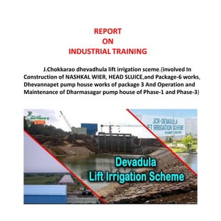
J.Chokkarao dhevadhula lift irrigation sceme.(involved In
Construction of NASHKAL WIER, HEAD SLUICE,and Package-6 works,
Dhevannapet pump house works of package 3 And Operation and
Maintenance of Dharmasagar pump house of Phase-1 and Phase-3)
2. INTRODUCTION
In this 6 months of industrial training we have been gone through the project named j.chokkarao
dhevadhula lift irrigation project, which includes construction of Nashkal wier, Head sluice and
package 6 works,Dhevannapeta pump house works and dharmasagar pump house works.
JCR DLIS is contemplated to ultimately lift 38.16 TMC of water from Godavari river near
Gangaram (V),Eturunagaram (M) to irrigate 6.21 Lakh acres including provision of drinking water
facility to enrooting villages of project in upland drought prone areas of undivided Warangal,
Karimnagar and Nalgonda Districts. The Government of Andhra Pradesh is programmed to take up
this Scheme in Three phases for speedy execution.The Phase-I & Phase-II works of JCR DLIS were
taken up under EPC Turnkey contract basis and the lift system were completed and distributory
systems are nearing completion. The proposed package-VI is included in the phase-III of JCR-
DLIS.The Part of Package-VI work which consists the following components:The Nashkal Main Canal
from NashkalTank to PalakurthyTank runs for a length of 21.850 km with sill level of Head Sluice is
fixed as +293.000 m with a carrying capacity for 52,725 Acres at Head Regulator. Earth work
Excavation and forming Embankment, Construction of CD & CM works and cement concrete lining
up to 1 Cusec discharge for main Canal Distributaries, Minors and Sub-Minors including filed
channels to provide irrigation potential of 45,210 Acres under Naskhal Tank, 7,515 Acres under
Palakurthy Tank and 25,165 Acres under Chennur Tank.
3. IMPORTANCE OF IRRIGATION CANALS
Irrigation canals are the main waterways that bring irrigation water from a water source to the
areas to be irrigated. They can be lined with concrete, brick, stone, or a flexible membrane to
prevent seepage and erosion.
An open canal, channel, or ditch, is an open waterway whose purpose is to carry water from
one place to another. Channels and canals refer to main waterways supplying water to one or more
farms. Field ditches have smaller dimensions and convey water from the farm entrance to the
irrigated fields. Canal irrigation does not let the water table level go down. It only helps to increase
the water level thus facilitating the digging of wells. Canals also serve the purpose of
hydroelectricity, drinking water supply, fishery development, and navigation.
CLASSIFICATION OF CANAL BASED ON
1. Nature of source of supply
2. Financial output
3. Function of canal
4. Discharge & Relative importance of canal in network
4. 1. Nature of source of supply
1. Permanent canal -
- Is fed from permanent source of water
- Aka perennial canal
- made of well graded channel with permanent structures
- Non-perennial canals
- get supply only during particular time of year
ii. Inundation canal -
- Gets water when stage in river is higher
- Headworks for diversions are not provided
2. Financial output
i. Productive
- once fully developed yields enough revenue to recover initial investment ii. Protective
- after construction serves as relief work during famine and protect area against future famines, generates employment
3. Function of canal
i. Irrigation canal - carries water to the agricultural field
ii. Carrier canal - along with irrigation, carries water for other canals
iii. Feeder canal - it feeds 2 or more canals
iv. Navigational canal - used for navigational purposes
v. Power canal - carries water from reservoir to turbine houses, it is located on canal where fall is available
4. Based on Discharge and relative importance of Canal
i. Main canal - carry water from rivers (dams) and feed to branch canals, distributaries. They do not supply
water directly to fields. Q will be in range of 30 - 150 cumecs
ii. Branch canal - they branch out at regular intervals from main canal on either sides. They are feeder canals &
supply water to major and minor distributaries. Not for direct irrigation. Q in range of 10 -30 cumecs.
iii. Major Distributaries - aka Rajbha - take off from branch canal and/or main canal & distribute water to field.
Q in range of 1 - 40 cumecs.
iv. Minor distributaries - aka Minors - similar to major distributaries, but have Q in range of 0.3 - 1 cumecs
v. Field channel - small channels, carry water from outlets to fields. Owned and constructed by farmers
5. DIFFERENT METHODS OF ALIGNMENT OF CANAL Canal Alignment
• Such that it commands entire area under irrigation with shortest length and least
cost of construction
• Shorter length- reduces frictional head loss, evaporation & seepage losses. •
Additional irrigation can be achieved by reduced losses.
Based on alignment we have Ridge/Watershed, Contour and Side slope canals.
• Ridge canal - runs along the watershed for most of its length. Can irrigate on both
sides of canal. Do not require cross drainage works (CDW). In case of sharp loops,
then alignment will be along straight line, which may need CDW.
6. • Contour canals
These canals are aligned nearly parallel to the contour.
They can irrigate only on one side. Ground level on one side is higher, so no need
to construct bank.
There can be single and or double bank canal CDW are required for these canals.
In case of hilly area, it can be aligned along watershed These canals cannot follow
single contour throughout as canal bed continuously changed.
Hence shifted from one to another contour
7. • Side slope canal
Aligned roughly at right angles to the contour
Canal is almost parallel to natural drainage, hence no CDW required
Irrigation is possible only on one side.
Canals have very steep bed slope, because the direction of steepest
slope of ground is at right angles to contour.
8. Considerations for Canal alignment
• Canal alignment shall be such that it should distribute the water in most economical way and larger command
area
• Number of CDW shall be minimum
• Length of main canal between source to watershed shall be minimum
• When the canals deviate from one contour to another, the alignment shall have less number of CDW
• Alignment should avoid places of importance and valuable properties.
• Alignment shall follow balanced depth of cutting and filling or minimum depth of cutting or filling
• Number of curves should be minimum
• Alignment shall not be through rocky or fishered rock
• Field canals shall be laid along boundaries • Separate field canals for high and low lands
• In hilly areas, it is difficult to align canal along ridge, as water flows in valley and ridge may
be several hundred meters high. A contour canal may be adopted.
9. Curves
• Should not be provided along the length of canal, except if necessary.
• Curves disturb the regime of channel
• Concave side will have erosion and Convex side will have deposition/silting.
An irrigation canal may be in any one of the following ways:
I. Canal in cutting
II. Canal in banking
III. Canal in partial cutting and partial banking
CANAL IN CUTTING:
When the full supply level and bed of the canal is below the natural surface
level (N.S.L) ,then the section is said to be “canal in cutting”
TYPICAL CROSS SECTION OF CANALS
10. CANAL IN BANKING:
When the bed level of the canal is above the natural surface level then the section
is said to be “canal in banking”
CANAL IN PARTIAL CUTTING AND PARTIAL BANKING:
When the full supply level of the canal is above the natural surface levels and bed level of the
canal is below the ground level the section is said to be “canal in partial cutting and partial
banking”
11. Head Regulator
• Regulators Constructed at the off taking point are called head regulators. When it is constructed at the head of
main canal it is known as canal head regulator. And when it is constructed at the head of distributary, it is called
distributary head regulator.
• Function:
• To control the entry of water either from the reservoir or from the main canal.
• To control the entry of silt into off taking or main canal.
• To serve as a meter for measuring discharge of water.
• Construction:
The components of head regulator depends upon the size of canal and location of head regulator. It consists of one
or more gated research openings with barrels running through the bank. For large canals head regulators are flumed
to facilitate the measurement of discharge
12. Cross Regulator
• A Regulator Constructed in the main canal or parent canal downstream of an off take canal is called
crossregulator.
• It is generally constructed at a distance of 9 to 12 km along the main canal and 6 to 10 km along branch
canal.
• Functions:
• (i) To Control the flow of water in canal system
• (ii) To feed the off taking Canals
• (iii) To enable closing of the canal breaches on the d/s
• (iv) To provide roadway for vehicular traffic
13. Construction:
For Cross Regulators abutments with grooves and piers are constructed parallel to the parent canal. The sill
of regulation is kept little higher than the u/s bed level of canal across which it is constructed. Vertical lift
gates are fitted in the grooves. The gates can be operate from the road.
• A canal outlet or a module is a small structure built at the head of the water course so as to
connect it with a minor or a distributary channel.
• It acts as a connecting link between the system manager and the farmers.
Canal Outlet/modules
14. Non-Modular Modules
• Non-modular modules are those through which the discharge depends upon the head difference
between the distributary and the water course. Common examples are:
(i) Open sluice
(ii) Drowned pipe outlet
• Due to construction, a super-critical velocity is ensured in the throat and thereby allowing the formation of a
jump in the expanding flume.
• The formation of hydraulic jump makes the outlet discharge independent of the water level in water course, thus
making it a semi module. Semi-modules or flexible modules are those through which the discharge is independent of
the water level of the water course but depends only upon the water level of the distributary so long as a minimum
working head is available.
• Examples are pipe outlet, open flume type etc
Semi-Modules or Flexible modules
15. Rigid Modules or Modular Outlets
• Rigid modules or modular outlets are those through which discharge is constant and fixed within limits,
irrespective of the fluctuations of the water levels of either the distributary or of the water course or both.
• An example is Gibb’s module:
A cross drainage work is a structure carrying the discharge from a natural stream across a canal intercepting the
stream. Canal comes across obstructions like rivers, natural drains and other canals. The various types of structures
that are built to carry the canal water across the above mentioned obstructions or vice versa are called cross drainage
works. It is generally a very costly item and should be avoided by
* Diverting one stream into another.
* Changing the alignment of the canal so that it crosses below the junction of two streams
1. Aqueduct
2. Super passage
3. Level crossing
4. Inlet and outlet
CROSS DRAINAGE WORKS
Definition:
16. Aqueduct:
When the HFL of the drain is sufficiently below the bottom of the canal such that the drainage waterflows freely
under gravity, the structure is known as Aqueduct.
* In this, canal water is carried across the drainage in a trough supported on piers.
* Bridge carrying water
* Provided when sufficient level difference is available between the canal and natural and canal bed is sufficiently
higher than HFL.
Siphon Aqueduct:
In case of the siphon Aqueduct, the HFL of the drain is much higher above the canal bed, and water runs under siphonic
action through the Aqueduct barrels. The drain bed is generally depressed and provided with pucci floors, on the upstream
side, the drainage bed may be joined to the pucca floor either by a vertical drop or by glacis of 3:1. The downstrean rising
slope should not be steeper than 5:1. When the canal is passed over the drain, the canal remains open for inspection
throughout and the damage caused by flood is rare. However during heavy floods, the foundations are succeptible to scour
or the waterway of drain may get choked due to debris, tress etc
Canal Syphon:
* If two canals cross each other and one of the canals is siphoned under the other, then the hydraulic structure at
crossing is called
17. “canal siphon”. For example, lower Jhelum canal is siphoned under the Rasul-Qadirabad (Punjab, Pakistan) link canal
and the crossing structure is called “L.J.C siphon”
* In case of siphon the FSL of the canal is much above the bed level of the drainage trough, so that the canal runs
under the siphonic action.
* The canal bed is lowered and a ramp is provided at the exit so that the trouble of silting is minimized.
* Reverse of an aqueduct siphon
* In the above two types, the inspection road cannot be provided along the canal and a separate bridge is required for
roadway
Bank of
Concrete floor
Type I:
Sides of the aqueduct in earthen banks with complete earthen slopes. The length of culvert should be sufficient to
accomodate both, water section of canal, as well as earthen banks of canal with aqueduct slope. Sides of the aqueduct in
earthen banks, with other slopes supported by masonry wall. In this case, canal continues in its earthen section over the
drainage but the outer slopes of the canal banks are replaced by retaining wall, reducing the length of drainage culvert.
Type II:
Sides of the aqueduct made of concrete or masonry. Its earthen section of the canal is discontinued and canal water is
carried in masonry or concrete trough, canal is generally flumed in this section
Type III:
Sides of the aqueduct in earthen banks, with other slopes supported by masonry wall. In this case, canal continues in its
earthen section over the drainage but the outer slopes of the canal banks are replaced by retaining wall, reducing the length
of drainage culvert
18. * The hydraulic structure in which the drainage is passing over the irrigation canal is known as super passage. This
structure is suitable when the bed level of drainage is above the flood surface level of the canal. The water of the canal
passes clearly below the drainage
* A super passage is similar to an aqueduct, except in this case the drain is over the canal.
* The FSL of the canal is lower than the underside of the trough carrying drainage water. Thus, the canal water runs
under the gravity.
* Reverse of an aqueducd
Super-passage
Super passage
19. Level crossing
^ When the bed level of canal and the stream are approximately the same and quality of water in canal and stream is
not much different, the cross drainage work constructed is called level crossing where water of canal and stream is
allowed to mix. With the help of regulators both in canal and stream, water is disposed through canal and stream in
required quantity.
^ Level crossing consists of following components
(i) crest wall
(ii) Stream regulator
(iii) Canal regulator
^ When irrigation canal meets a small stream or drain at same level, drain is allowed to enter the canal as in inlet. At
some distance from this inlet point, a part of water is allowed to drain as outlet which eventually meets the original
stream. Stone pitching is required at the inlet and outlet. The bed and banks between inlet and outlet are also protected
by stone pitching.This type of CDW iscalled Inlet and Outlet.
^ There are many disadvantages in use of canal inlet structure, because the drainage may pollute canal water and also
the bank erosion may take place causing the canal structure deteriorate so that maintenance costs are high. Hence this
type of structure is rarely constructed
Inlet and Outlet
20. LINING
Canal lining is the process of reducing seepage loss of irrigation water by adding an impermeable layer to the edges of
the trench. Seepage can result in losses of 30 to 50 percent of irrigation water from canals, so adding lining can make
irrigation systems more efficient. Canallinings are also used to prevent weed growth, which can spread throughout an
irrigation system and reduce water flow. Lining a canal can also prevent waterlogging around low-lying areas of the
canal.
By making a canal less permeable, the water velocity increases resulting in a greater overall discharge. Increased
velocity also reduces the amount of evaporation and silting that occurs, making the canal more efficient.The oldest
known paved canal was discovered in 1995 near the pyramids of Giza, and is estimated to be around 4,500 years old
21. Advantages of Canal Lining
1 .It reduces the loss of water due to seepage and hence the duty is enhanced.
2. It controls the water logging and hence the bad effects of waterlogging are eliminated.
3. It provides smooth surface and hence the velocity of flow can be increased.
4. Due to the increased velocity the discharge capacity of a canal is also increased.
5. Due to the increased velocity, the evaporation loss also can be reduced.
6. It eliminates the effect of scouring in the canal bed
7. The increased velocity eliminates the possibility of silting in the canal bed.
8 It controls the growth of weeds along the canal sides and bed.
10. It provides the stable section of the canal.
11. It reduces the requirements of land width for the canal,
because smaller section of the canal can be used to produce greater discharge.
12. It prevents the sub-soil salt to come in contact with the canal water.
13. It reduces the maintenance cost for the canals.
22. Disadvantages of canal lining:
1. The initial cost of the canal lining is very high. So, it makes the project very expensive with respect to the output.
2. It involves many difficulties for repairing the damaged section of lining.
3. It takes too much time to complete the project work.
4. It becomes difficult, if the outlets are required to be shifted or new outlets are required to be provided, because the
dismantling of the lined section is difficult.
Maintenance and repair works
The performance of an irrigation canal system depends not only on how the system is operated, but also on the condition
of the canals. Irrigation canals function well so long as they are kept clean and if they are not leaking. If no attention is
paid to the canal system, plants may grow and the problem of siltation may arise. Even worse, the canals may suffer from
leakages
It is not just the smaller, tertiary irrigation canals that need to be maintained, it is the primary and secondary canals as
well. Sometimes these canals may be located far from the farmers’ fields and this can be one reason why farmers show
no interest in maintaining them. However, the smaller canals receive water from these canals and so maintenance of the
larger canals is of vital importance for the proper functioning of the whole system
Even when a canal is well maintained, serious technical problems may arise. These problems need to be solved by repair
or improvement works. A repair should usually be done as soon as possible, depending on the severity of the problem.
Improvements, such as the lining of a canal section, may be postponed until the end of an irrigation season,when canals
are dry and farmers have more time available.
After a serious problem is found on an inspection tour, a team of workers or farmers should be available for repair as
soon as possible. Such a team should be formed at the beginning of the irrigation season in order to have it on call in
case of emergencies. The same team may be asked to do the improvement works. If necessary, a contractor may be
asked to do the job.
23. Single Lane Road Bridge (SLRB)
single lane road or one-lane road is a road that permits two-way travel & traffics but it is not wide enough in most
places to allow vehicles to pass one another (although sometimes two compact vehicles such as car can pass). The
distance between passing places varies considerably, depending on the terrain and the volume of traffic on the road.
A Single lane road consists of two main component carriageway for travelling & traffic and shoulder for vehicles to
pass one another.
Width of a single lane road consist of carriageway width & margin width. Width of margin comprises width of
pavement shoulder and unpaved shoulder. A carriageway generally consists of a number of traffic lanes together with
any associated shoulder. Road margin is the portion of road beyond the carriageway.
Shoulder are provided along the road edge and on intended for accommodation of stop vehicles, serve as an
emergency lane for vehicles and provide lateral support. Shoulder should be strong enough to bear the weight of fully
loaded truck even in wet condition. Shoulder width should be required for giving working space, ideal width of
shoulder should be 4.6 m and minimum is about 2.5 m. Width of shoulder also depending on available space and
elevation of surface such as plain area mountain area or hilly area. In Mountain area it is quite difficult to construct a
road so width of shoulder is minimised and their width is less than in plain area.
24. Weir
The Weir is a solid obstruction or wall built across the river to
raise the water level and divert the water into the canal. It is
located just below the off take point of the main Canal. Weir also
stores water over small period of short supplies. It is called
storage weir.
Some times shutters also are provided over the crest of the weir
to build up to desired water level on the U/S. Weirs are also called
as Anicuts. A Weir is also be called as low head dam.
The main difference between a weir and a dam is only in
height and the duration for which the supply is stored.The height of
the dam is more and supply the stored water for longer periods
25. Sluices
Sluice are the openings or conduits extending from U/S face of the
dam to D/S face of the dam.They are used to clean the silt from the reservoir
or to supply water to the D/S of the reservoir. Also they decrease the peak
flood in the reservoir
The openings provided in the body wall of
the weir almost at the bed level of the river are called
scouring sluice.
Functions :
1. To allow the low river floods to pass safely.
2. To maintain a clear and defined river channel approaching the
head Regulator.
3. They help in removing the silt near the head regulators or control
the entry of silt into the canal.
26. Right from the start of training we have learned about Distribution works of canal is ...it
aim..objectives.. component parts of Distribution works of canal And we learnt about uses,
advantages, disadvantages , types of Distribution works of canal discharge. And we also learnt
how to do de-siltation and we learnt about canal regulator works, lining, revetment, and also
about water cement ratio for lining. And we learnt about maintenance of irrigation canal and so
many etc,.
The villagers are fully depending on rain fed well irrigation. The rainfall is the erotic in this area
and there is no chance for recharging of ground water. The canal is proposed to store and supply
water. The villagers are fully satisfied by irrigation canals
Conclusion
Editor's Notes
In this 6 months of industrial training we have been worked upon the project named j.chokkarao dhevadhula lift irrigation project which includes construction of Nashkal wier, Head sluice and package 6 works dhevannapeta pump house works and Dharmanagar pump house.