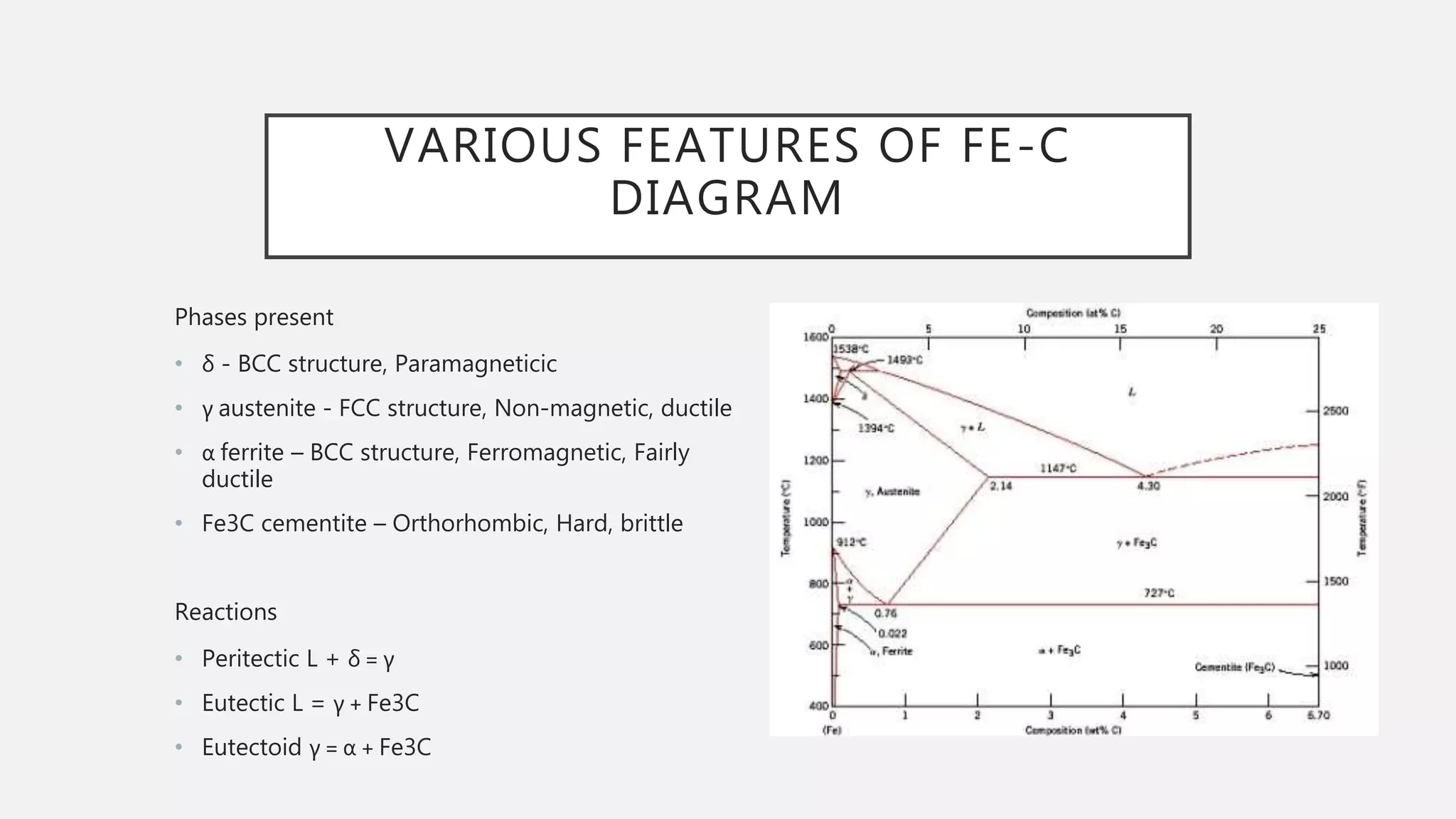
This document provides an overview of the iron-carbon phase diagram, including:
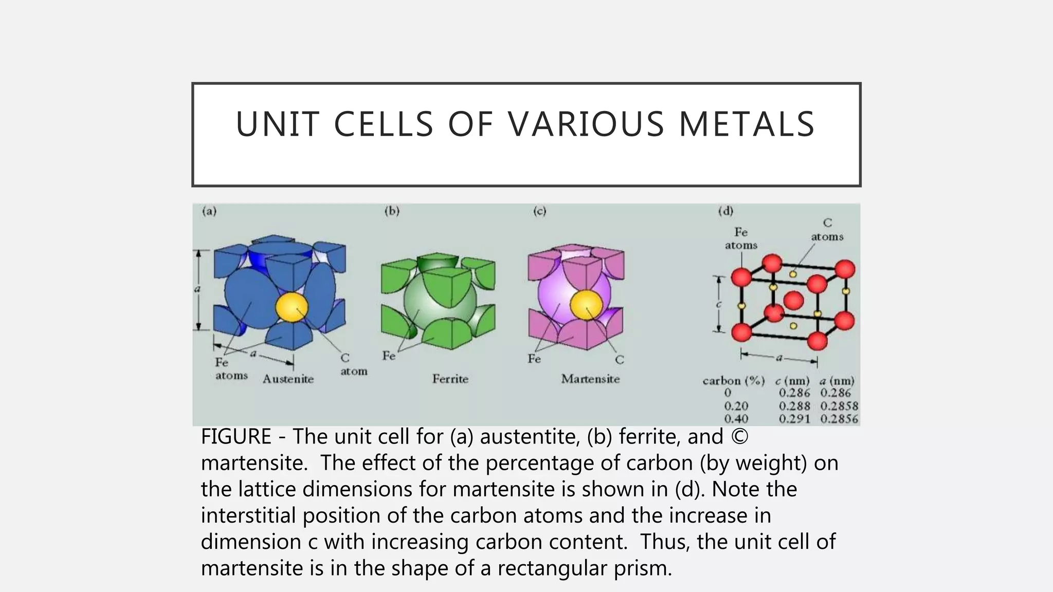
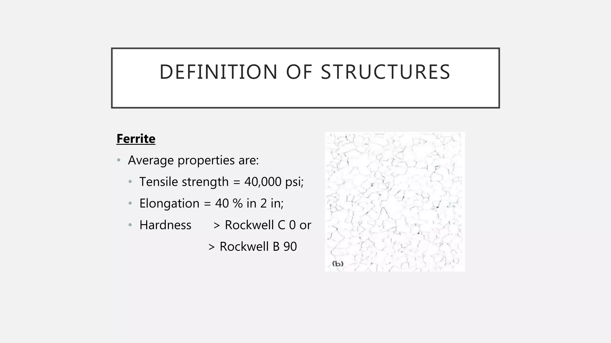
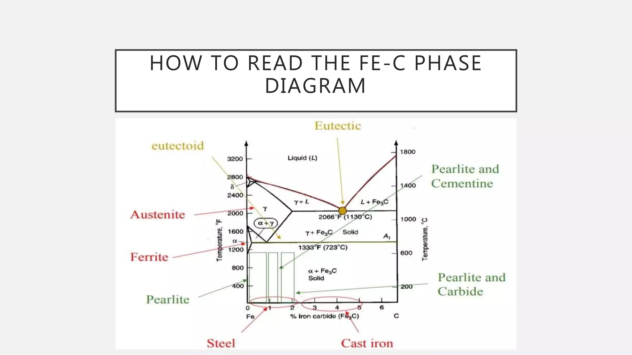
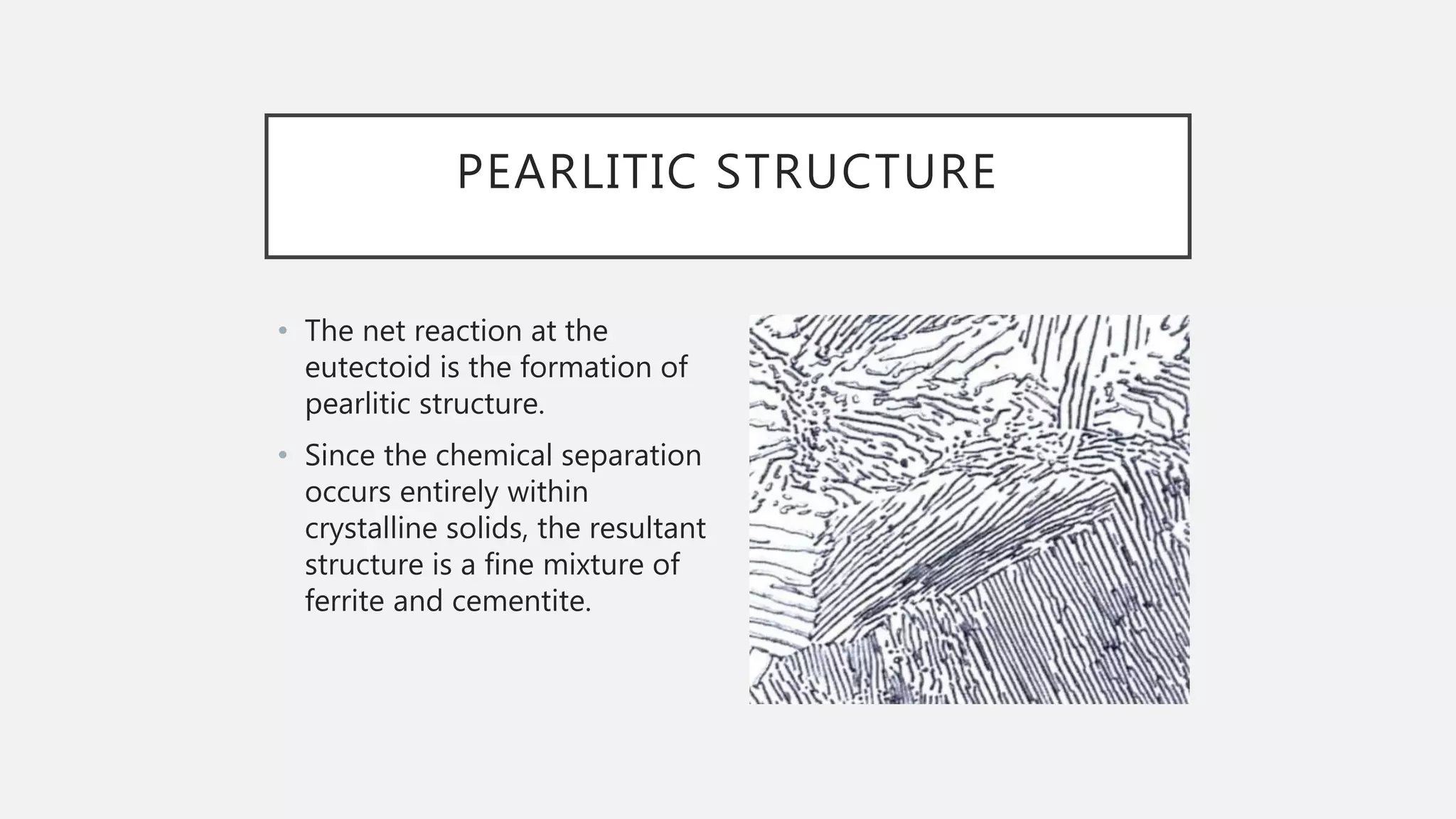
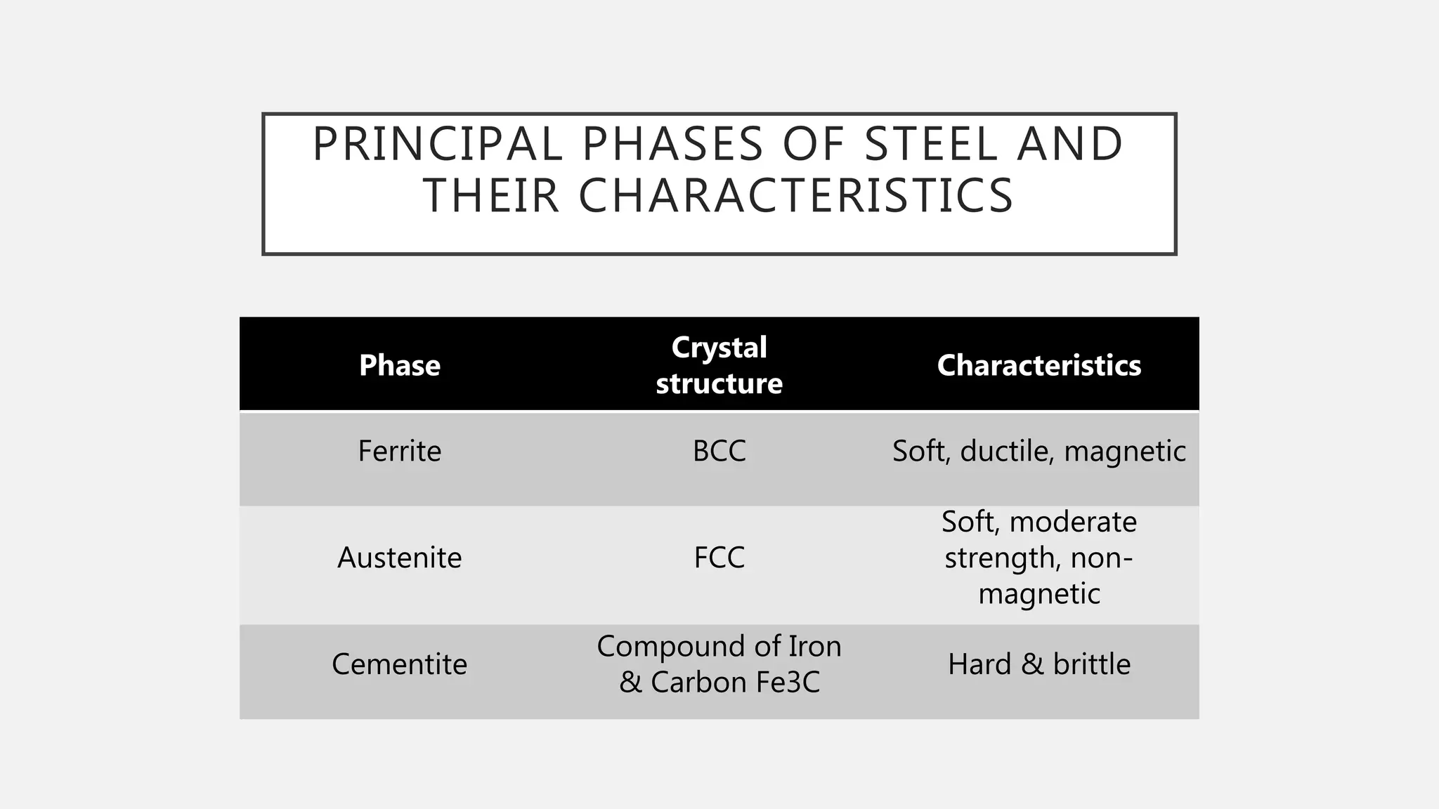
1) It defines the various phases that appear on the diagram such as austenite, ferrite, pearlite, cementite, and martensite.
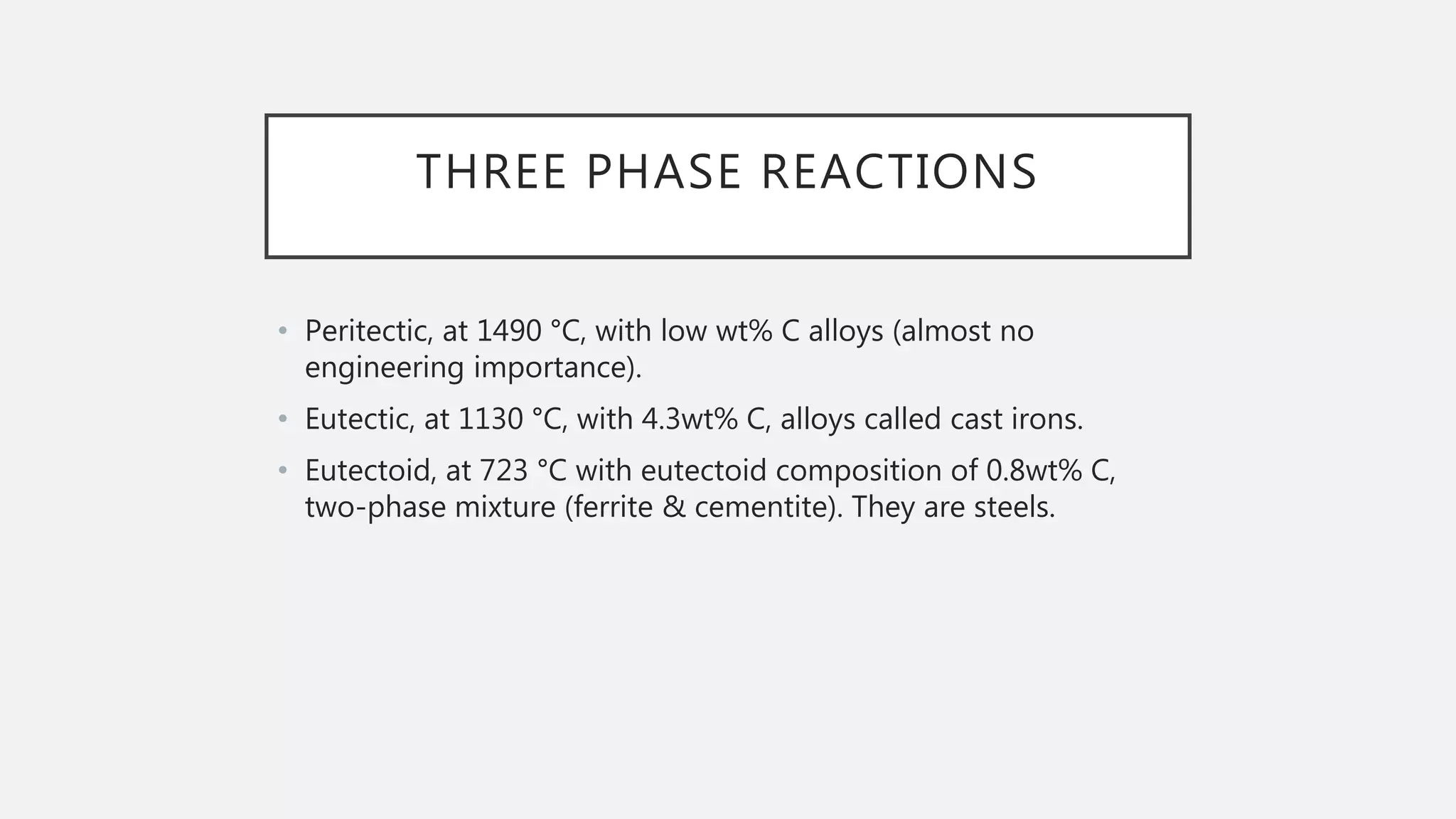
2) It explains the three main phase changes that occur - peritectic, eutectic, and eutectoid reactions.
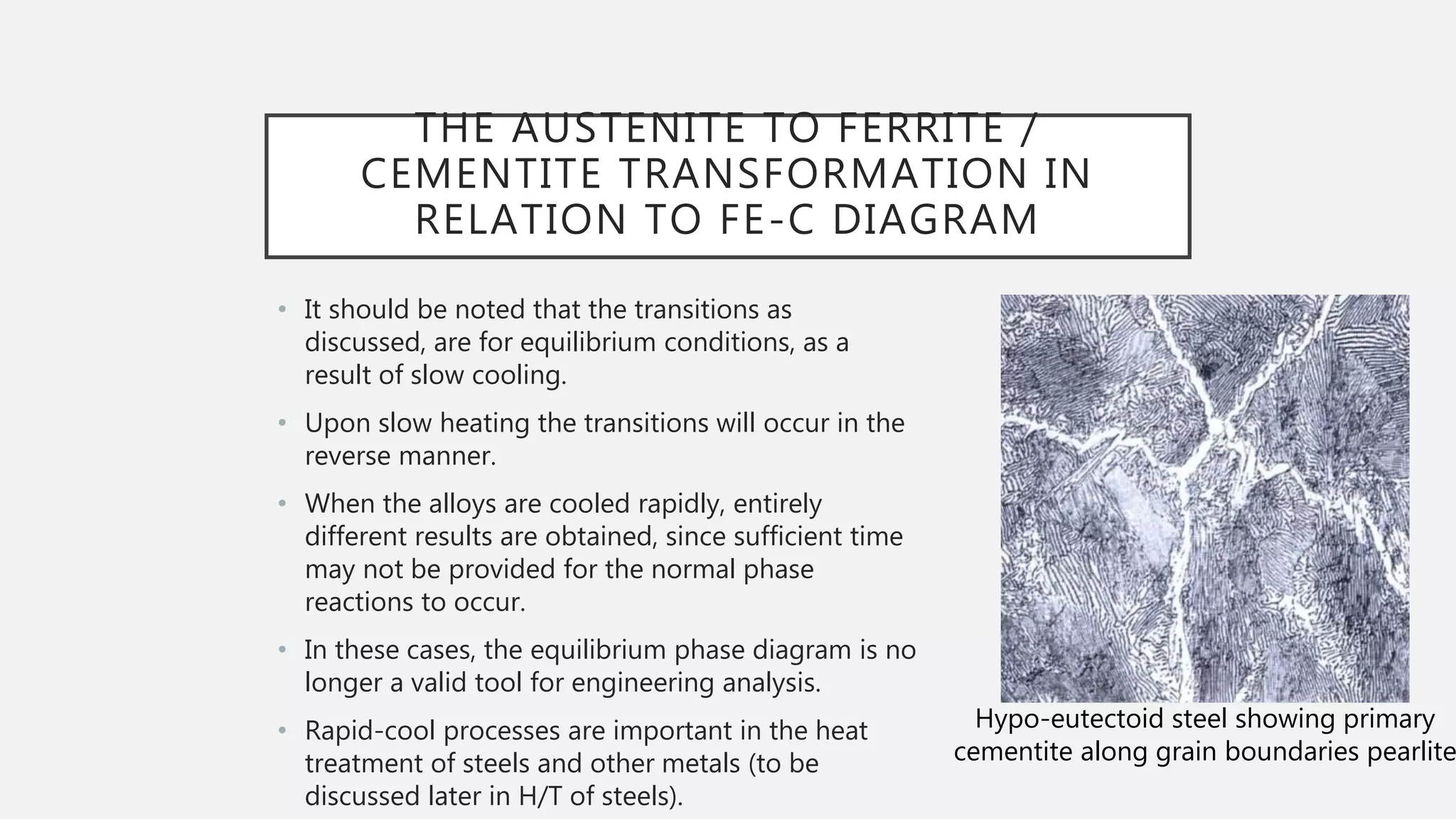
3) It describes how the microstructure of steel depends on the carbon content, including the transformations between austenite, ferrite, and cementite that produce hypoeutectoid, eutectoid, and hypereutectoid microstructures.