Download to read offline
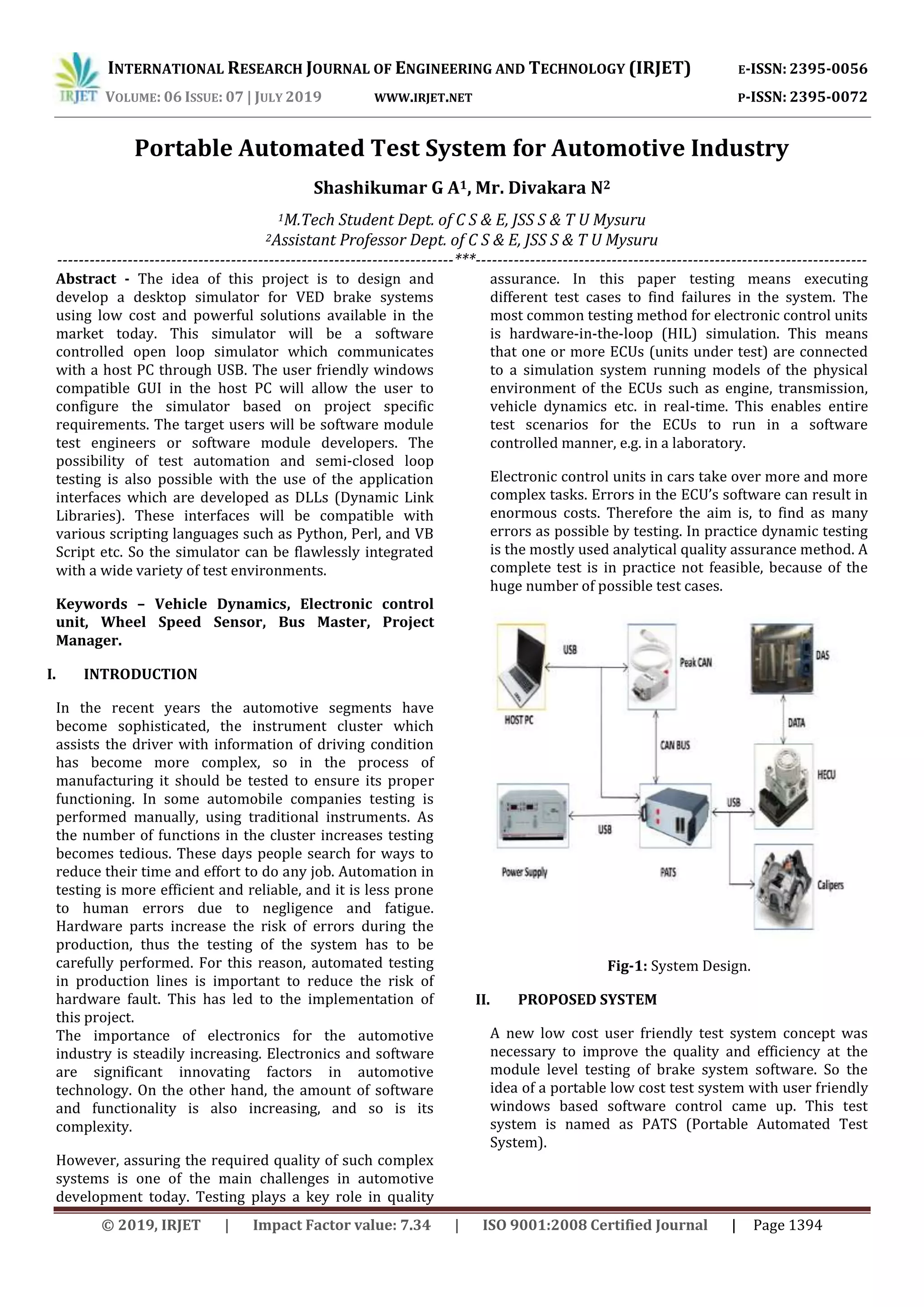
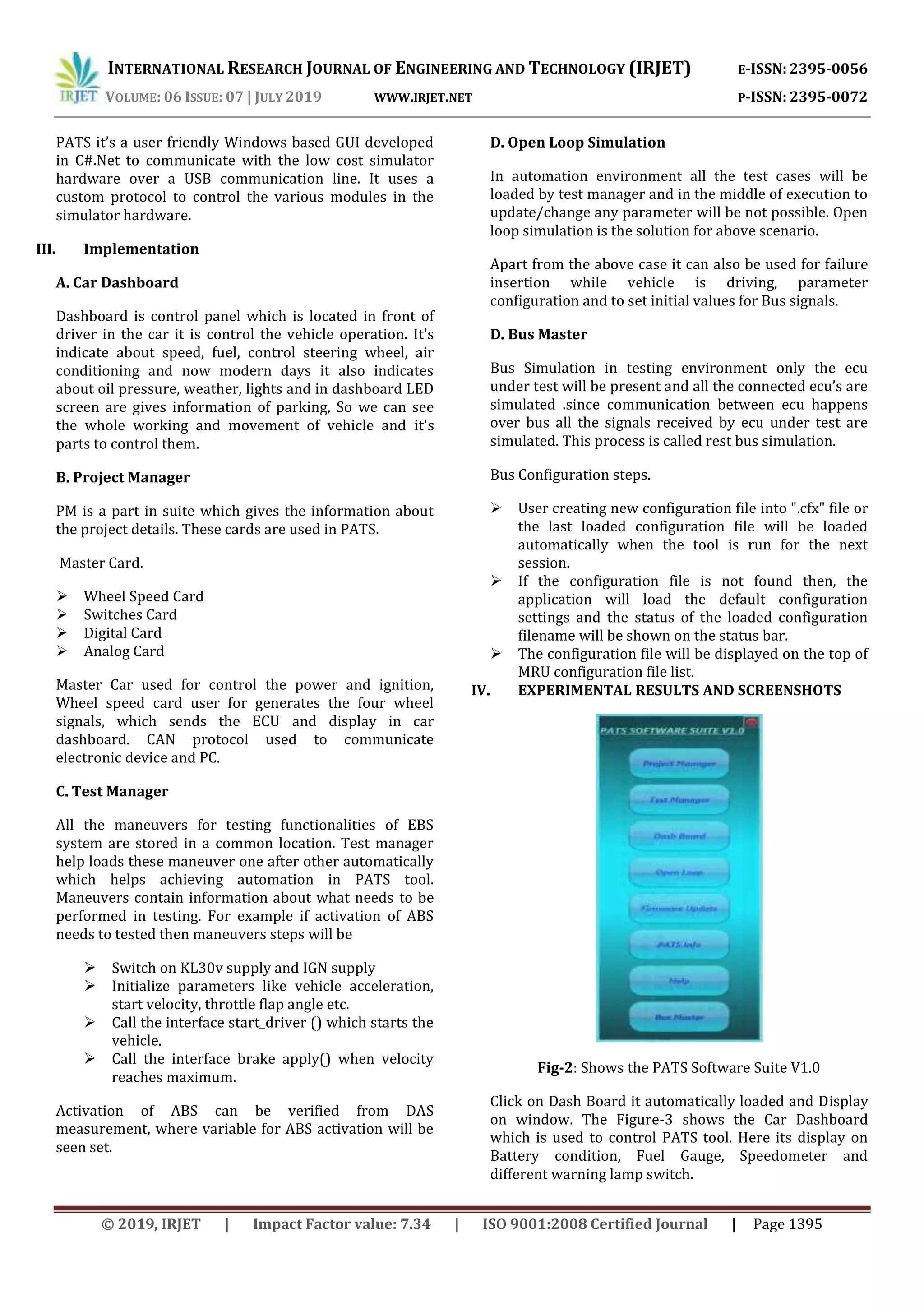


This document describes a portable automated test system (PATS) developed for testing brake systems in the automotive industry. PATS includes a desktop simulator with a user-friendly GUI that allows configuration of test scenarios. It communicates with a hardware simulator over USB. The system allows automation of tests and integration with various scripting languages. It provides a low-cost and effective way to test brake system software modules.


