Download to read offline
![International Research Journal of Engineering and Technology (IRJET) e-ISSN: 2395-0056
Volume: 06 Issue: 07 | July 2019 www.irjet.net p-ISSN: 2395-0072
© 2019, IRJET | Impact Factor value: 7.211 | ISO 9001:2008 Certified Journal | Page 387
Fig -1: Block diagram of CNC machine
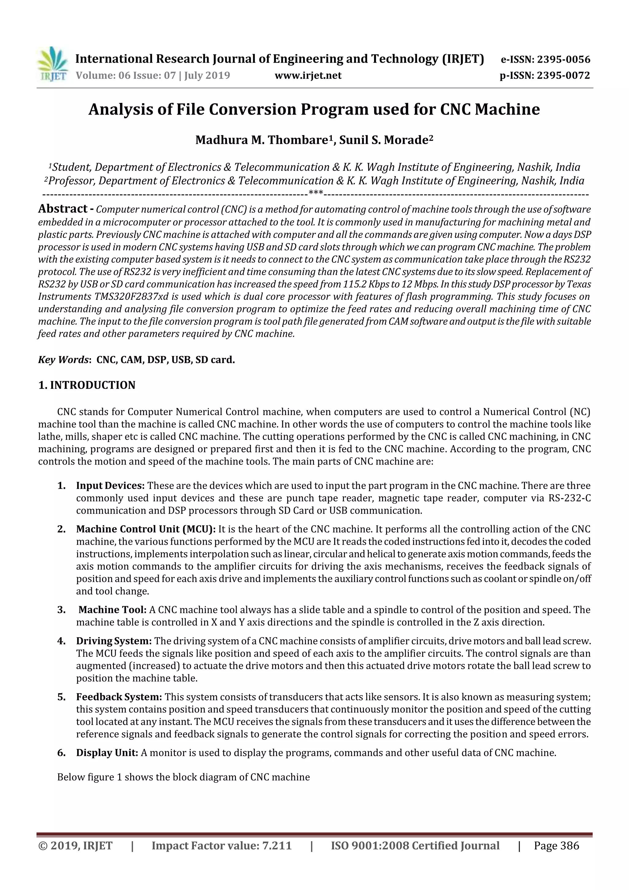
The user of CNC machine give commands to CNC machine for its operation and this commands are in the form of tool
path file, this file is generated using CAD/CAM software. This tool path file contains information regarding the distances of
points from X-Y axis, feed, plunge acceleration time, etc. But we cannot give this file as it is to CNC machine because the
parameters given by user are not always suitable to CNC machine. If that tool path file is given as it is then it may harm cutting
tool, crate vibrations or degrade life of CNC machine. So this file goes from various file conversion processes and finallyweget
file suitable for CNC machine. So main objective of this project is to understand the flow of file conversionutility,optimizefeed
rate and minimize machining time in tool path file.
Initially, the CNC technology was applied on basic metal cutting machines suchaslathe, millingmachines,etc.Then,to
increase flexibility of the machines in handling a variety of components and to finish them in a single setup on the same
machine, CNC concept was applied to develop a CNC machining centre for machining prismatic components combining
operations like milling, drilling, boring and tapping. It does so by taking computer-generated code and converting it with
software into electrical signals. The signals control the CNC motors anddirectthemto moveinsmall incrementsthatarehighly
precise and repetitive [7]. To get a CNC machine work properly, there needs a dictated software control to get the desired
results from a computer design. Traditional CNC machines programmed using CAM software, [3] this CAM (computer aided
manufacturing) program is the most difficult part. Note that the CAM doesn't actually run the machine, though it creates the
code for machine to follow. In addition, some machines have their own programming language and specificCAMisrequiredto
create NC code for the machine to understand. In these cases it can require a post processor that serves to bridge the gap in
communication [4]. The post processor usually makes it possible touseanymachineandtranslateanythingtothe neededcode
for specific machine and part.
There are many smaller model maker-hobbyist styledesktopCNCmachines[2].Ingeneral thesearelighterinweight,lessrigid,
less precise, slower and less expensive than their industrial counterparts, but can do well for machining objects for softer
materials like plastics, foam, and wax. Some desktop CNC machines may run a lot like a printer. Others have their own closed
command system and even dedicated CAM software. A few machines will alsoacceptstandardG-codeasinput;someindustrial
standard desktop machines do exist with dedicated controllers for doing precise and small work.
2. SYSTEM OVERVIEW
As the mathematical calculations required for numerical data goes onincreasingtheprocessingtimeforCNCwill also
increases. To reduce the processing time of machine the use of DSP processorinCNCsystemhasbeenincreasedtremendously.
The requirement of electrical drive systems increases by the request of high performance, large integration, ease of
programming and lower cost. Based on these new trends and requirements TI developed a new controller concept which
integrates a Digital Signal Processor (DSP) core with intelligent peripherals to achieve single chip solution. TI developed the
new controller family TMS320F2837xD to achieve the processing goals required in CNC machine. Due to the mathematical
calculations required for numerical data goes on increasing the processing time and complexity for CNC will also increase.
When someone is operating on CNC machine with some tool then he has to insure that it will not get damaged because of feed,
speed and plunge given by user in input tool path file. To prevent the damage of machine it is necessary to find out the
maximum acceptable feed and speed for the machine tool.](https://image.slidesharecdn.com/irjet-v6i767-191101070630/75/IRJET-Analysis-of-File-Conversion-Program-Used-for-CNC-Machine-2-2048.jpg)
![International Research Journal of Engineering and Technology (IRJET) e-ISSN: 2395-0056
Volume: 06 Issue: 07 | July 2019 www.irjet.net p-ISSN: 2395-0072
© 2019, IRJET | Impact Factor value: 7.211 | ISO 9001:2008 Certified Journal | Page 389
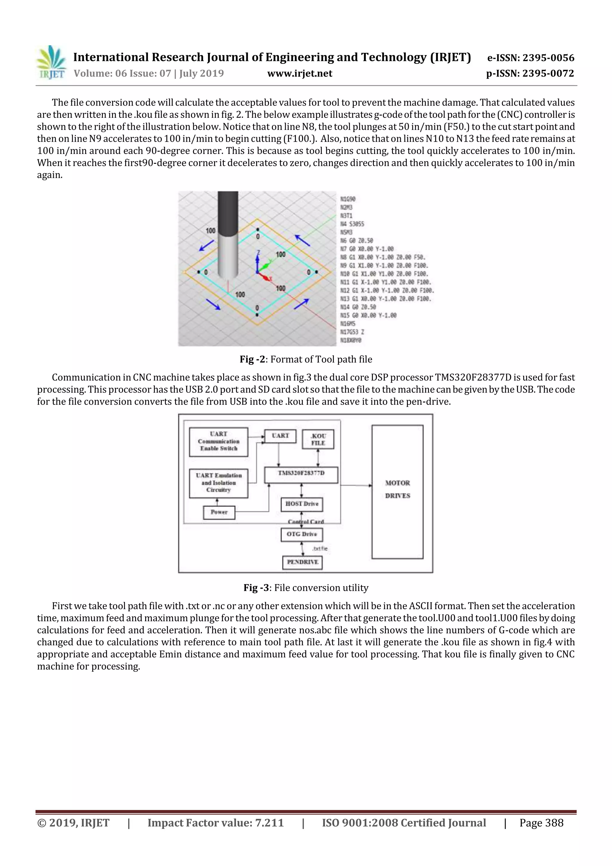
Fig -4: General flow of file conversion in CNC machine.
Steps to generate tool path file:
1. Read the .txt file from pen drive which is called as tool path file.
2. Convert .txt file into the tool.U00 file by doing some calculations of axis parameters.
3. Convert the tool.U00 file into tool1.U00 file by again doingthe calculations of maximumfeed and minimumlinear
distance (Emin) for tool processing.
4. Generate the nos.abc file which will indicate the line numbers Generate the .kou file by with suitable feed and
distance values
Initially file conversion program checks if tool path file is present or not. If it is present then write parameters like
acceleration time, feed and plunge into config file which is created by file conversion code. And if input tool path file is not
present then first accept it from user and ask for parameters like acceleration time, feed, and plunge. Finally write this
parameters into config file and calculate minimum distance Emin by formula given as,
Emin = [ (long) (Maxf / 60) ] * Acctime
Here, Maxf is maximum allowable feed.
Acctime is acceleration time.
The main function of the code generates the tool.U00 file after reading the tool path file and doing the required mathematical
calculations. The tool1.U00 file will be createdininterpritfunctionafterreadingthetool.U00fileandagaindoingthecalculations
for the total value. After generating the tool1.U00 file, the programwillgeneratethenos.abcfileinevaluatefunction.Thenos.abc
file will indicatethe line numbers where the feed value changes are supposed to occur. The nos.abc file iscreatedbyreadingthe
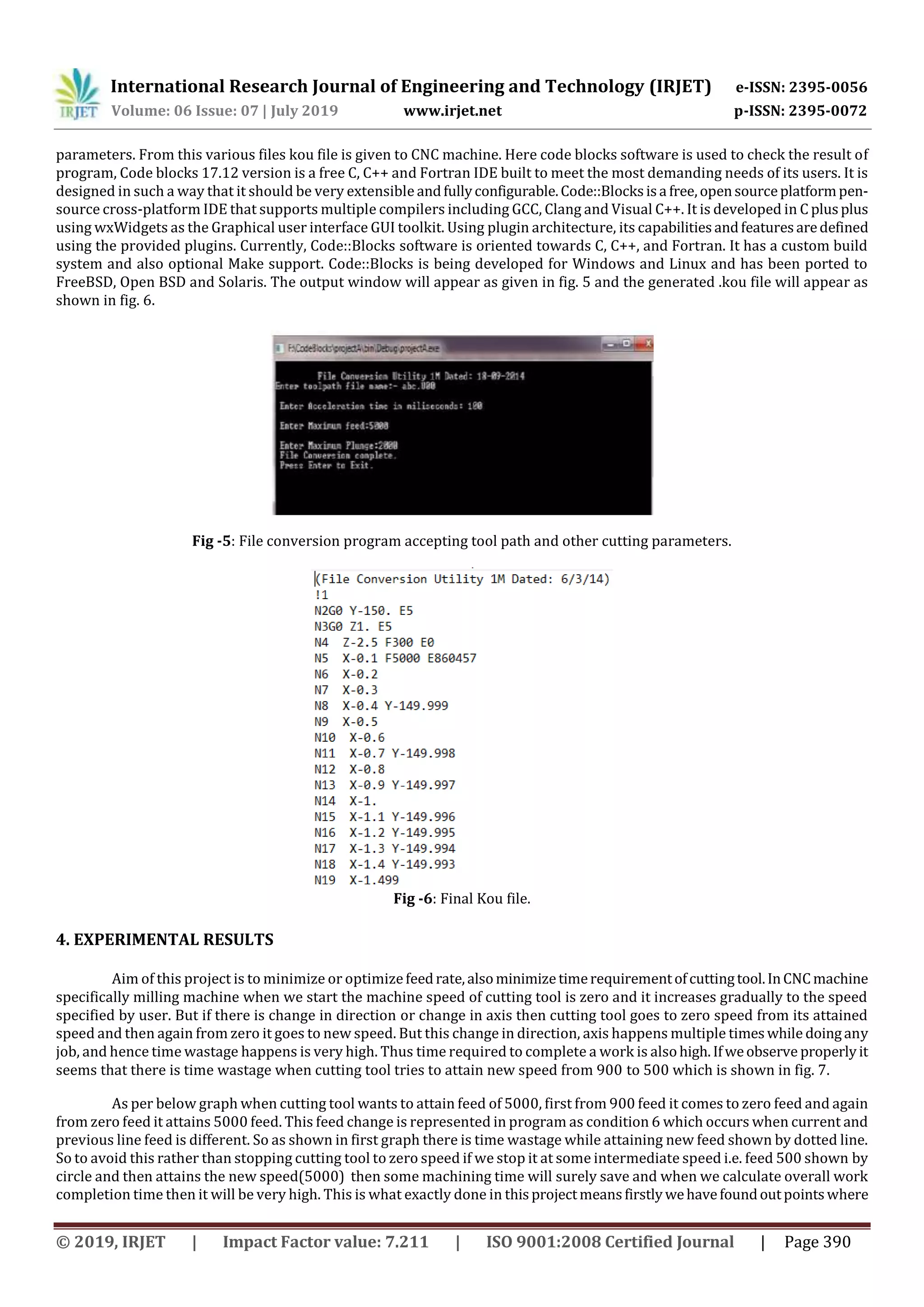
tool1.U00 file. The .kou is the final file to give to the CNC machine, the kou file will be generated in evaluate function in the code.
To create the kou file there is need to refer the two file. First is nos.abc file and second is tool path file. In kou file the required
feed and speed will get added for the tool processing.
3. SOFTWARE DESIGN
By giving feed, acceleration, plunge and tool path file as an input to file conversion code various files like kou, config
file, nos file, etc are generated. These files are generated after tremendous calculations on feed, acceleration, plunge, etc](https://image.slidesharecdn.com/irjet-v6i767-191101070630/75/IRJET-Analysis-of-File-Conversion-Program-Used-for-CNC-Machine-4-2048.jpg)
![International Research Journal of Engineering and Technology (IRJET) e-ISSN: 2395-0056
Volume: 06 Issue: 07 | July 2019 www.irjet.net p-ISSN: 2395-0072
© 2019, IRJET | Impact Factor value: 7.211 | ISO 9001:2008 Certified Journal | Page 392
REFERENCES
[1] "ToolpathFeedrate Optimization: A Case Study Proceedings of the 2000 NSF Design and Manufacturing Research
Conference", Jan 3-6, 2000, Vancouver, British Columbia, Canada. .
[2] E. Missimer, Y. Li and R. West, "Real-time USB communication in the Quest operatingsystem",2013IEEE 19thReal-Time
and Embedded Technology and Applications Symposium (RTAS), Philadelphia, PA, 2013, pp. 11-20.
[3] J. W. Jeon, "Efficient acceleration and deceleration technique for short distance movement in industrial robots and CNC
machine tools,"Electronics Letters, vol. 36, no. 8, pp. 766-768, 2000
[4] TMS320F2837xD Dual-Core Delfino Microcontrollers Technical Reference Manual.
[5] F2837xD Workshop Workshop Guide and Lab Manual F2837xD-TTO by TI.
[6] T. C. Lu and S. L. Chen, "Genetic algorithm-based S-curve acceleration and deceleration for five-axis machine tools,"
International Journal of Advanced Manufacturing Technology, pp. 1-14, 2016.
[7] https://wiki.mcneel.com/rhino/cncbasics.
[8] https://pdfs.semanticscholar.org/b99e/cb86fcdce222c0182de991892482c2a19471.pdf
[9] Jin-Shiang Chang and Syh-Shiuh Yeh, Member, IAENG, “Development of an Interpolation Method for the
Acceleration/Deceleration Period Spanning Over Multiple Numerical Control Blocks in CNC Machine Tools”,Vol II IMECS
2018, March 14-16, Hong Kong, 2018.
[10] C. W. Cheng and M. C. Tsai, "Real-time variable feed rate NURBS curve interpolator for cnc machining," International
Journal of Advanced Manufacturing Technology, vol. 23, no. 11-12, pp. 865-873, 2004.](https://image.slidesharecdn.com/irjet-v6i767-191101070630/75/IRJET-Analysis-of-File-Conversion-Program-Used-for-CNC-Machine-7-2048.jpg)

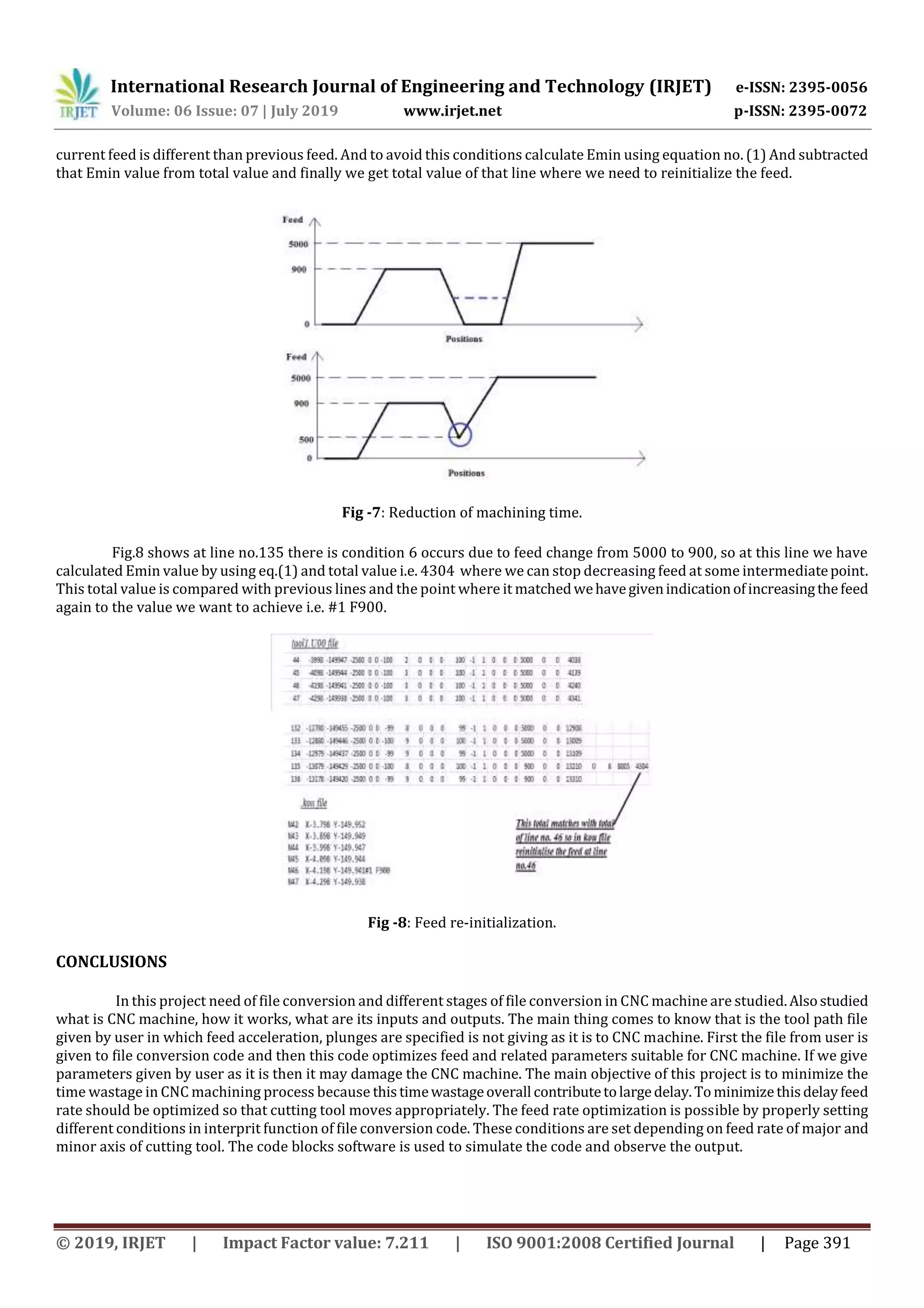
This document describes a file conversion program used to optimize feed rates and reduce machining time for CNC machines. The program takes as input a tool path file generated from CAM software. It then calculates acceptable feed rates and other parameters required by the CNC machine. The output is a .kou file with the optimized parameters. The program aims to minimize machining time by avoiding having the cutting tool slow down to zero speed when changing directions or feed rates, and instead allows it to slow to an intermediate speed. This reduces unnecessary acceleration and deceleration time. The file conversion process and goals of optimizing feed rates and machining time are discussed.