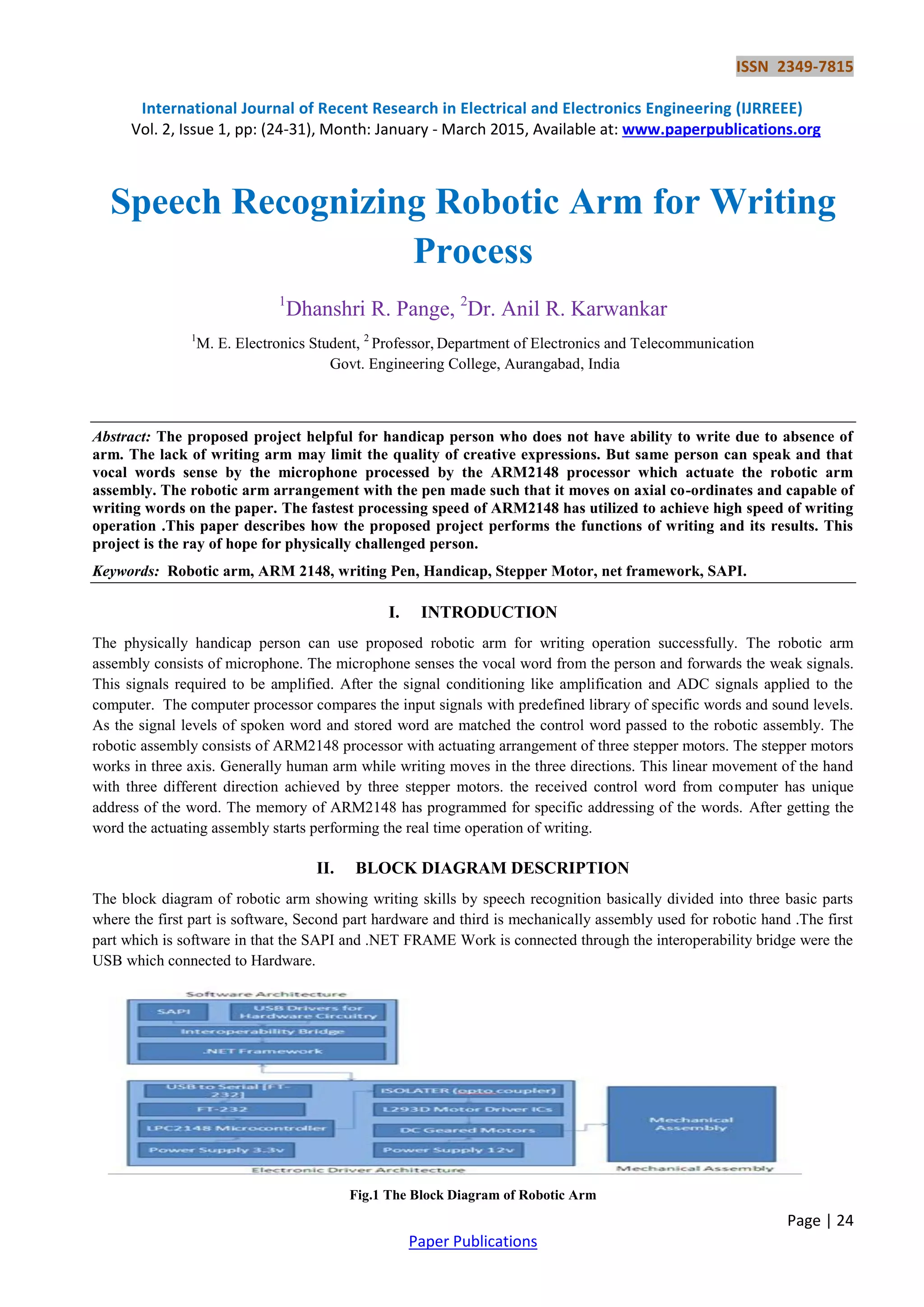
1) The document describes a robotic arm system that allows physically handicapped individuals to write using speech recognition. The system uses a microphone to capture spoken words, which are processed by an ARM2148 processor and used to control stepper motors that move a pen in three axes to write on paper.
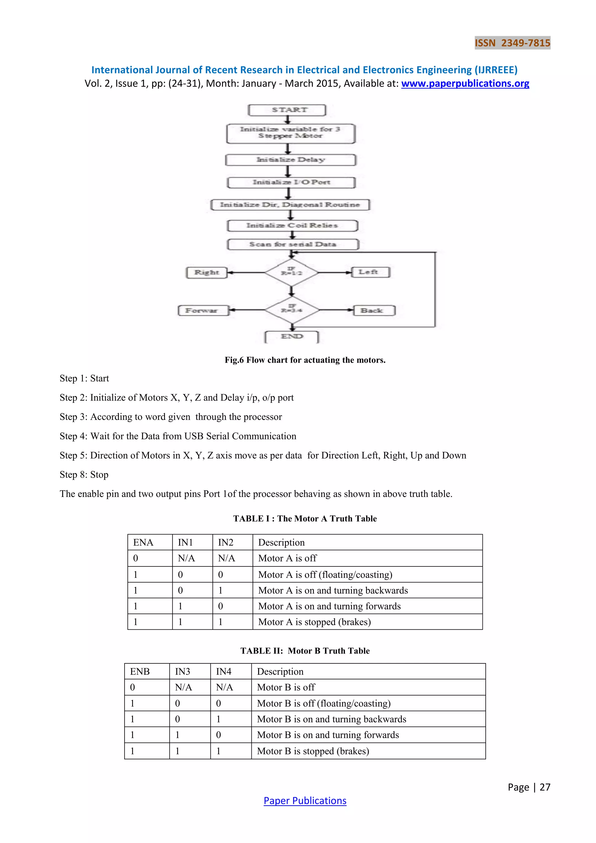
2) The system was tested on 18 words with a single user and showed some errors differentiating similar sounding words. When tested with 3 users, recognition success rates ranged from 67-94% depending on the word.
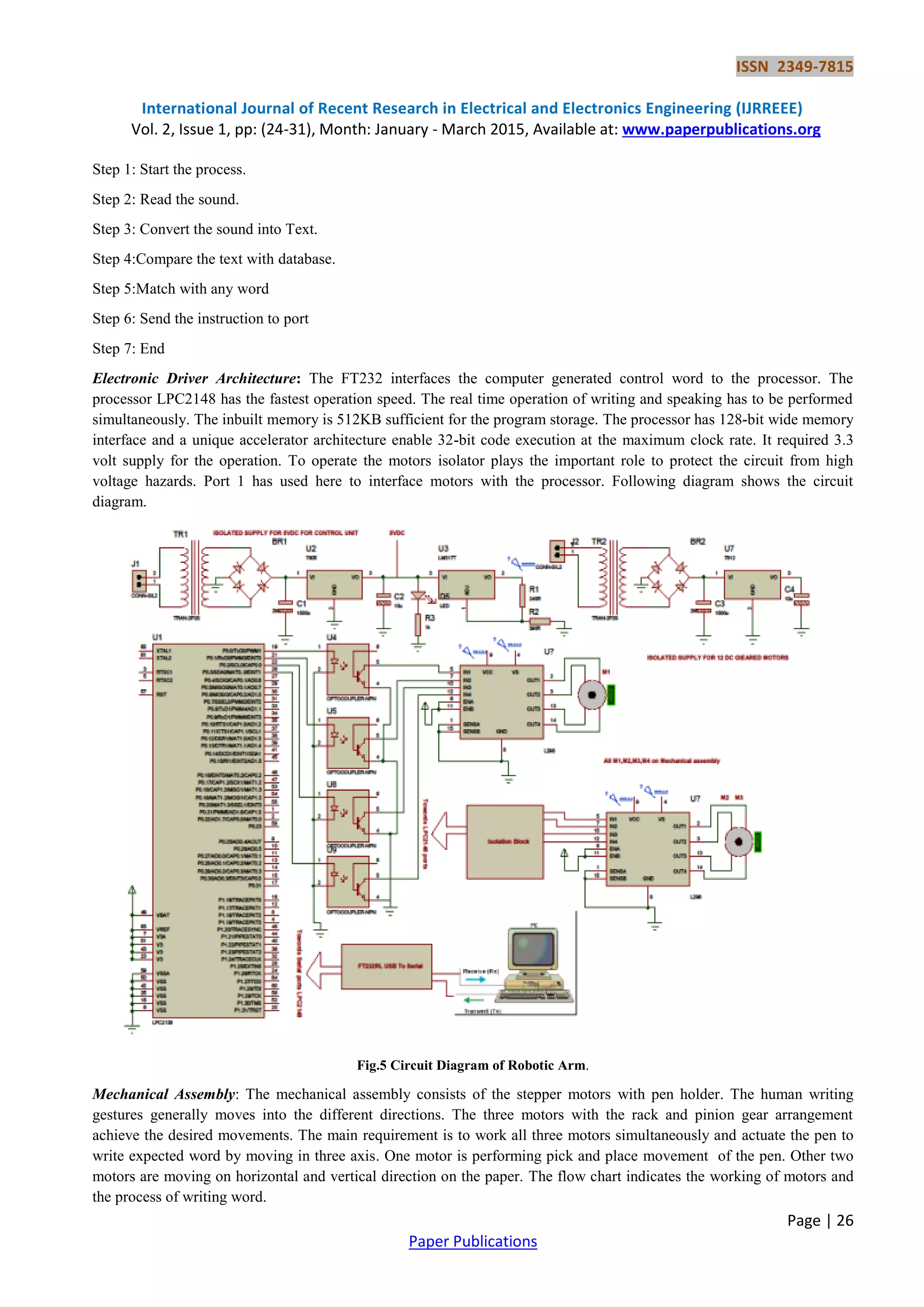
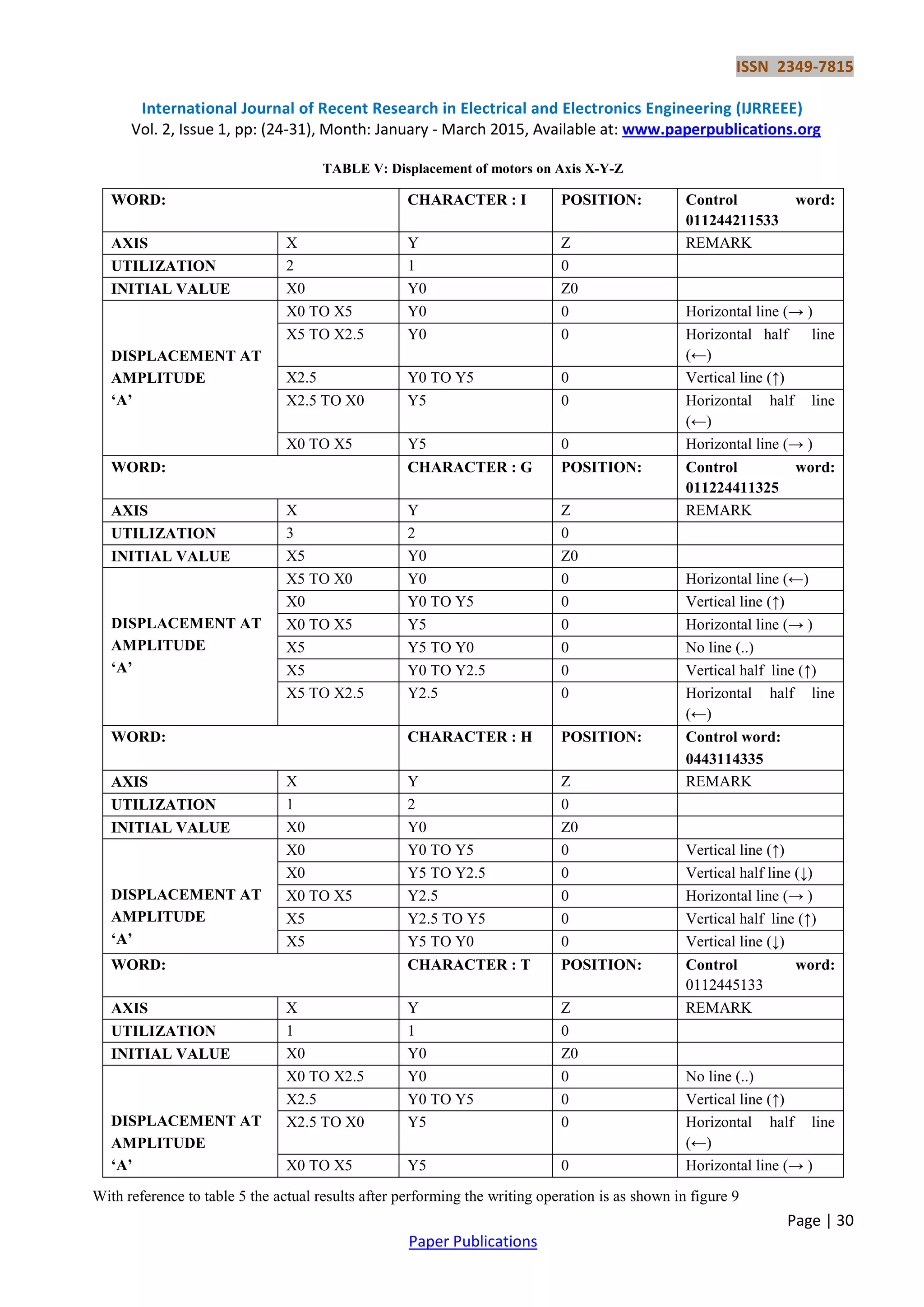
3) The processor receives the recognized word and uses unique control signals to move the stepper motors accordingly in X, Y, and Z axes to write individual letters or characters on the paper. Several examples are

![ISSN 2349-7815
International Journal of Recent Research in Electrical and Electronics Engineering (IJRREEE)
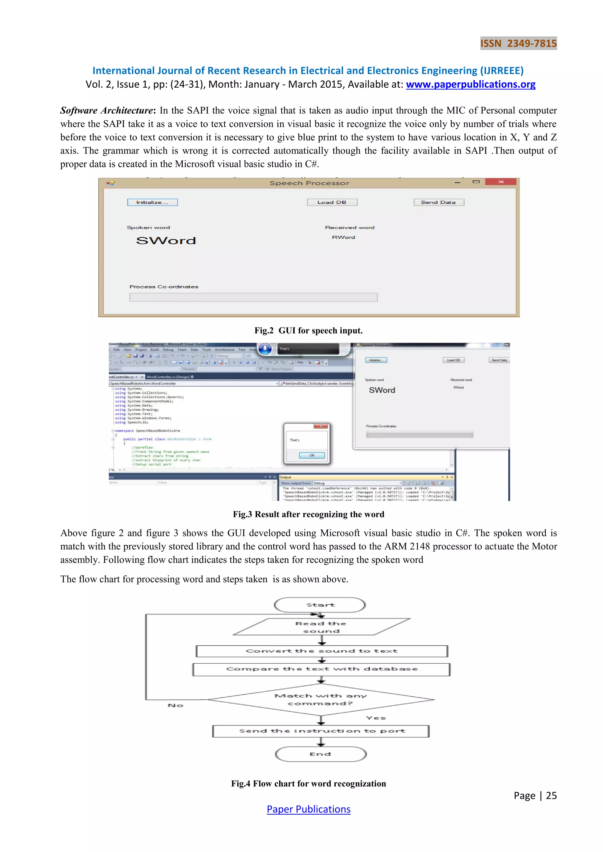
Vol. 2, Issue 1, pp: (24-31), Month: January - March 2015, Available at: www.paperpublications.org
Page | 31
Paper Publications
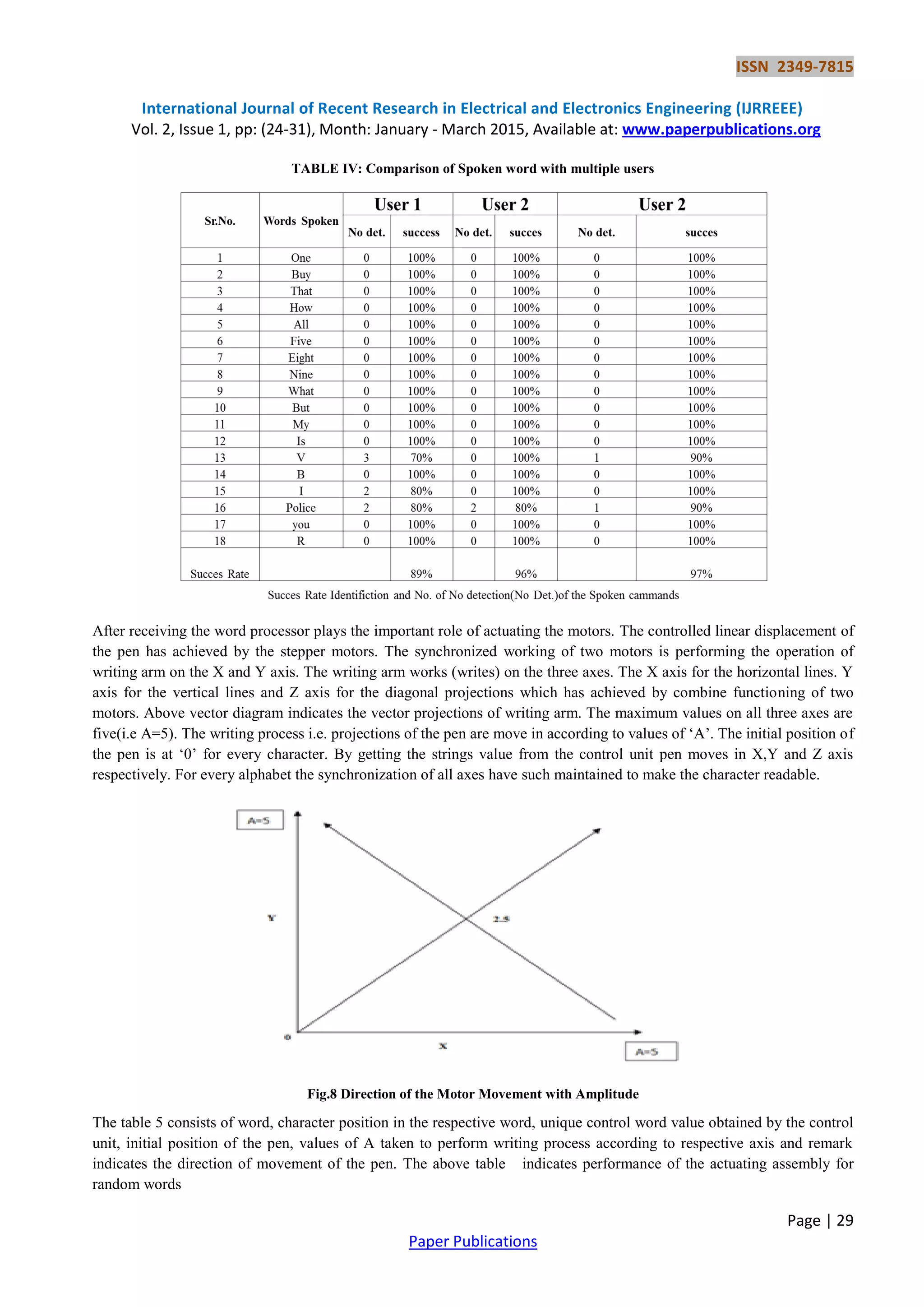
Fig. 9 Actual characters written by the writing arm
IV. CONCLUSION
The capacity of human being to express in the form of writing should not be hampered due to accidental cause. the
proposed project gives 'helping ' hand for such people to come up and above the valley of darkness. The results designate
the success of robotic arm. With the help of described project the handicap person can write and express the views and
opinion in the written manner.
REFERENCES
[1] Fundamentals of Speech Recognition; Lawrence Rabiner & Biing - Hwang Juang Englewood Cliffs NJ: PTR
Prentice Hall (Signal Processing series), C1993
[2] Speech Synthesis and Recognition; J.N Holmes Wokingham: Van Nostrand Reinhold, C1988
[3] Electronic Speech recognition: techniques, technology and applications, edited by Geoff Bristow, London: Collins,
1986
[4] Peatman J.B., “Design with ARM Microcontrollers”, Prentice Hall, 1997, ISBN-10: 0137592590. Neural
computation, v1 (1), pp 1-38, 1989
[5] Iovine J, “ARM Robotics: A Beginner‟s Guide to Robotics Projects Using The ARM micro”, Mc-Graw Hill, 2004,
ISBN 0071394559.](https://image.slidesharecdn.com/speechrecognizingroboticarmforwritingprocess-149-170329095623/75/Speech-Recognizing-Robotic-Arm-for-Writing-Process-8-2048.jpg)