SlideShare a Scribd company logo
1 of 30
Download to read offline
Yatin Kumar Singh Page 1
Gears
Gears are toothed members which transmit power / motion between two shafts by meshing without any slip. Hence,
gear drives are also called Positive Drives. In any pair of gears, the smaller one is called Pinion and the larger one is
called Gear immaterial of which is driving the other.
When pinion is the driver, it results in step down drive in which the output speed decreases and the torque increases.
On the other hand, when the gear is the driver, it results in step up drive in which the output speed increases and the
torque decreases.
Classification of Gears
Gears are classified according to the shape of the tooth pair and disposition into spur, helical, double helical, straight
bevel, spiral bevel and hypoid bevel, worm and spiral gears.
Spur Gears
Spur gears have their teeth parallel to the axis and are used for transmitting power between two parallel shafts. They
are simple in construction, easy to manufacture and cost less. They have highest efficiency and excellent precision
rating. They are used in high speed and high load application in all types of trains and a wide range of velocity ratios.
Hence, they find wide applications right from clocks, household gadgets, motor cycles, automobiles, and railways to
aircrafts.
(a) Spur Gear (b) Helical Gear (c) Internal Gear (d) Worm and Worm Gear
Helical Gears
Helical gears are used for parallel shaft drives. They have teeth inclined to the axis as shown in Fig. 1.9. Hence for the
same width, their teeth are longer than spur gears and have higher load carrying capacity. Their contact ratio is higher
than spur gears and they operate smoother and quieter than spur gears. Their precision rating is good. They are
recommended for very high speeds and loads. Thus, these gears find wide applications in automotive gearboxes. Their
efficiency is slightly lower than spur gears. The helix angle also introduces axial thrust on the shaft.
Double Helical Gear or Herringbone Gear
Double helical or Herringbone gears used for transmitting power between two parallel shafts. They have opposing
helical teeth with or without a gap depending on the manufacturing method adopted. Two axial thrusts oppose each
other and nullify. Hence the shaft is free from any axial force. Though their load capacity is very high, manufacturing
difficulty makes them costlier than single helical gear. Their applications are limited to high capacity reduction drives
like that of cement mills and crushers.
Yatin Kumar Singh Page 2
Internal Gear
Internal gears are used for transmitting power between two parallel shafts. In these gears, annular wheels are having
teeth on the inner periphery. This makes the drive very compact. In these drives, the meshing pinion and annular gear
are running in the same direction. Their precision rating is fair. They are useful for high load and high speed
application with high reduction ratio. Applications of these gears can be seen in planetary gear drives of automobile
automatic transmissions, reduction gearboxes of cement mills, step-up drives of wind mills.
They are not recommended for precision meshes because of design, fabrication, and inspection limitations. They
should only be used when internal feature is necessary. However, today precision machining capability has led to
their usage even in position devices like antenna drives.
Rack and Pinion
Rack is a segment of a gear of infinite diameter. The tooth can be spur or helical. This type of gearing is used for
converting rotary motion into translatory motion or visa versa.
Rack and Pinion Double Helical Gear
Straight Bevel Gear
Straight bevel gears are used for transmitting power between intersecting shafts. They can operate under high speeds
and high loads. Their precision rating is fair to good. They are suitable for 1:1 and higher velocity ratios and for right-
angle meshes to any other angles. Their good choice is for right angle drive of particularly low ratios. However,
complicated both form and fabrication limits achievement of precision. They should be located at one of the less
critical meshes of the train. Wide application of the straight bevel drives is in automotive differentials, right angle
drives of blenders and conveyors.
Spiral Bevel Gear
Spiral bevel gears are also used for transmitting power between intersecting shafts. Because of the spiral tooth, the
contact length is more and contact ratio is more. They operate smoother than straight bevel gears and have higher
load capacity. But, their efficiency is slightly lower than straight bevel gear.
Hypoid Bevel Gear
These gears are also used for right angle drive in which the axes do not intersect. This permits the lowering of the
pinion axis which is an added advantage in automobile in avoiding hump inside the automobile drive line power
transmission. However, the non – intersection introduces a considerable amount of sliding and the drive requires
good lubrication to reduce the friction and wear. Their efficiency is lower than other two types of bevel gears. These
gears are widely used in current day automobile drive line power transmission.
Yatin Kumar Singh Page 3
Straight Bevel Gear Hypoid Bevel Gear Spiral Gear
Worm Gear
Worm and worm gear pair consists of a worm, which is very similar to a screw and a worm gear, which is a helical
gear. They are used in right-angle skew shafts. In these gears, the engagement occurs without any shock. The sliding
action prevalent in the system while resulting in quieter operation produces considerable frictional heat. High
reduction ratios 8 to 400 are possible. Efficiency of these gears is low anywhere from 90% to 40 %. Higher speed ratio
gears are non-reversible. Their precision rating is fair to good. They need good lubrication for heat dissipation and for
improving the efficiency. The drives are very compact. Worm gearing finds wide application in material handling and
transportation machinery, machine tools, automobiles etc.
Spiral Gear
Spiral gears are also known as crossed helical gears. They have high helix angle and transmit power between two non-
intersecting non-parallel shafts. They have initially point contact under the conditions of considerable sliding
velocities finally gears will have line contact. Hence, they are used for light load and low speed application such as
instruments, sewing machine etc. Their precision rating is poor.
Characteristics of Gears
Spur Gear:
 The teeth are straight and parallel to the shaft axis.
 Transmits power and motion between rotating two parallel shafts.
Features:
 Easy to manufacture
 There are no axial force
 Relatively easy to produce high-quality gears
 The most common type of gear
Applications:
 Transmission components
Helical Gear:
 The teeth are twisted oblique to the gear axis.
Helix Direction (Helix Hand):
 The hand of helix is designated as either left or right
 Right-hand and left-hand helical gears mate as a set. But they must have the same helix angle
Yatin Kumar Singh Page 4
Features:
 Has higher strength compared with a spur gear
 More effective in reducing noise and vibration when compared with a spur gear
 Gears in mesh produce thrust forces in the axial direction
Applications:
 Transmission components, automobile, speed reducers, etc.
Gear Rack:
 The rack is a bar containing teeth on one face for meshing with a gear.
 The basic rack form is the profile of a gear of infinite diameter.
 Racks with machined ends can be joined together to make any desired length.
Features:
 Changes a rotary motion into a rectilinear motion and vice versa
Applications:
 A transfer system for machine tools, printing presses, robots, etc.
Internal Gear:
 An annular gear having teeth on the inner surface of its rim.
 The internal gear always meshes with an external gear.
Features:
 When meshing two external gears, the rotation occurs in the opposite directions. When meshing an internal gear with
an external gear the rotation occurs in the same direction
 Care should be taken with regard to the number of teeth on each gear when meshing a large (internal) gear with a
small (external) gear, since three types of interference can occur
 Usually internal gears are driven by small external gears
 Allows for a compact design of the machine
Applications:
 Planetary gear drive of high reduction ratios, clutches, etc.
Yatin Kumar Singh Page 5
Bevel Gear:
Picture: Bevel gear, apex and pitch cone
One of a pair of gears used to connect two shafts whose axes intersect, and the pitch surfaces are cones. Teeth are cut
along the pitch cone. Depending on tooth trace, bevel gear is classified as:
1. Straight Bevel Gear
2. Spiral Bevel Gear
Straight Bevel Gear Spiral Bevel Gear Miter Gear
Straight Bevel Gear:
 A simple form of bevel gear having straight teeth which, if extended inward, would come together at the intersection
of the shaft axes.
Features:
 Relatively easy to manufacture
 Provides reduction ratios up to approx. 1:5
Applications:
 Machine tools, printing presses, etc. Especially suitable for use as a differential gear unit
Spiral Bevel Gear:
 Bevel gear with curved, oblique teeth to provide gradual engagement and larger contact surface at a given time than
an equivalent straight bevel gear.
Features:
 Has higher contact ratio, higher strength and durability than an equivalent straight bevel gear
 Allows a higher reduction ratio
Yatin Kumar Singh Page 6
 Has better efficiency of transmission with reduced gear noise
 Involves some technical difficulties in manufacturing
Applications:
 Automobiles, tractors, vehicles, final reduction gearing for ships. Especially suitable for high-speed, heavy load drives
Miter Gears:
 A special class of bevel gear where the shafts intersect at 90° and the gear ratio is 1:1.
 It is used to change the direction of shaft rotation without change in speed.
Screw Gear Worm, Worm Gear and Center distance
Screw Gear:
A helical gear that transmits power from one shaft to another, nonparallel, nonintersecting shaft
Features:
 Can be used as a speed reducer or as a speed increaser
 Due to sliding contact, has higher friction
 Not suitable for transmission of high horsepower
Applications:
 Driving gear for automobile. Automatic machines that require intricate movement
Worm Gear:
 Worm is a shank having at least one complete tooth (thread) around the pitch surface and is the driver of a worm
wheel.
 Worm Gear (worm wheel) is a gear with teeth cut on an angle to be driven by a worm.
 The worm gear pair is used to transmit motion between two shafts which are at 90°to each other and lie on a plane.
Features:
 Provides large reduction ratios for a given center distance
 Quiet and smooth meshing action
 It is not possible for a worm wheel to drive a worm unless certain conditions are met
Applications:
 Speed reducers, anti reversing gear devices making the most of its self-locking features, machine tools, indexing
devices, chain blocks, portable generators, etc.
Yatin Kumar Singh Page 7
Nomenclature
The Pitch Circle is a theoretical circle upon which all calculations are usually based; its diameter is the pitch
diameter. The pitch circles of a pair of mating gears are tangent to each other. A pinion is the smaller of two mating
gears. The larger is often called the gear.
The Circular Pitch p is the distance, measured on the pitch circle, from a point on one tooth to a corresponding point
on an adjacent tooth. Thus the circular pitch is equal to the sum of the tooth thickness and the width of space.
The Module m is the ratio of the pitch diameter to the number of teeth. The customary unit of length used is the
millimeter. The module is the index of tooth size in SI.
The Diametral Pitch P is the ratio of the number of teeth on the gear to the pitch diameter. Thus, it is the reciprocal of
the module. Since diametral pitch is used only with U.S. units, it is expressed as teeth per inch.
The Addendum a is the radial distance between the top land and the pitch circle.
The Dedendum b is the radial distance from the bottom land to the pitch circle. The whole depth ht is the sum of the
addendum and the dedendum.
Yatin Kumar Singh Page 8
The Clearance Circle is a circle that is tangent to the addendum circle of the mating gear. The clearance c is the
amount by which the dedendum in a given gear exceeds the addendum of its mating gear.
The Backlash is the amount by which the width of a tooth space exceeds the thickness of the engaging tooth
measured on the pitch circles.
= −
= −
=
�
= � −
= � −
where
P = diametral pitch, teeth per inch; N = number of teeth; d = pitch diameter, in; m = module, mm; d = pitch diameter,
mm; p = circular pitch
Involute Gear
This figure indicates how two involute teeth in mesh are moving to transmit rotary motion. Rotational sequence of the
gears: P1- P2- P3 When Gear 1 drives Gear 2 by acting at the instantaneous contact point, the contact point moves on
the common tangent in the order of P1- P2- P3. The contact point rolls along the involute curves of the gears.
Moreover, the points P1, P2 and P3 lie on the common tangent to the two base circles. It is similar to the point, P, on a
criss-crossed belt as the disks rotate. In effect, the involute shape of the gear teeth allows the contact point to move
smoothly, transmitting the motion. Therefore, the involute curve is the ideal shape for gear teeth.
Features:
 Conjugate action is relatively independent of small errors in center distance
 Can be manufactured at low cost since the tooth profile is relatively simple
 Its root thickness makes it strong
 A typical tooth profile used almost exclusively for gears.
Yatin Kumar Singh Page 9
Law of Gearing
The fundamental law of gearing states that the angular velocity ratio between the gears of a gear set must remain
constant throughout the mesh. This amounts to the following relationship:
�
�
= = =
In order to maintain constant angular velocity ratio between two meshing gears, the common normal of the tooth
profiles, at all contact points with in mesh, must always pass through a fixed point on the line of centers, called pitch
point.
Profiles Satisfying Law of Gears
Profiles which can satisfy the law of gearing are shown in Fig. a to c. These are (a) involute (b) cycloidal and (c)
circular arc or Novikov. Among these, cycloidal was the first to be evolved. This is followed by the invention of
involute profile which replaced many of the other profiles due to several technological advantages. Circular arc or
Novikov profile has some advantages over the other profiles. But due to manufacturing difficulties, it did not become
popular. However with powder metallurgy process it is slowly getting into industry now for specific application.
Fig. Profiles satisfying the law of gearing, (a) involute (b) cycloidal and (c) Circular arc
Fig.1.23 The generation of involute profile on right side Fig.1.24 The generation of involute profile on left side
Involute Gear Tooth Profile
Involute is the path generated by the end of a thread as it unwinds from a reel. In order to understand what is
involute, imagine a reel with thread wound in the clockwise direction as in Fig. Tie a knot at the end of the thread. In
the initial position, the thread is at B0 with knot on the reel at C0. Keeping the reel stationary, pull the thread and
Yatin Kumar Singh Page 10
unwind it to position B1. The knot now moves from C0 to C1. If the thread is unwound to position B2 the knot moves
to C2 position. In repeated unwinding, the taut thread occupies position B3, B4 while the knot moves to C3, C4
positions. Connect these points C0 to C4 by a smooth curve, the profile obtained is nothing but an involute, the
illustration of which is given below. This forms the left side part of the tooth profile. If similar process is repeated with
thread wound on the reel in anticlockwise direction in the same position, it forms the right side part of the same tooth.
The completely formed involute tooth is shown in Fig.
Fig.1.25 Involute gear tooth profile appearance after generation Fig. 1.26 Gear meshing
Involute profiles have special properties. Imagine two involute teeth in contact as shown in Fig.1.26. If a normal is
drawn at the contact point to the involute profile, it will be tangent to the generating circles. This can be visualized
better from Fig. 1.23 where the taut thread is normal to the profile as well as tangent to the reel which forms the
generating or the base circle. The profile will be involute above the base circle only. Below the base circle the profile
will not be involute.
The common normal to the profile at the contact point will be tangent to the base circles. It passes through a fixed
point lying at the intersection of the tangent to the rolling/pitch circles and the line connecting the centres of the gear
wheels. This point is known as the pitch point. As the gears rotate the contact point travels along the common tangent
to the base circle. Hence this line is also known as the line of action. The movement of the contact point along the line
of action can be seen in the gear meshing later on.
Advantages of Involute Gears
1. Variation in centre distance does not affect the velocity ratio.
2. Pressure angle remains constant throughout the engagements which results in smooth running.
3. Straight teeth of basic rack for involute admit simple tools. Hence, manufacturing becomes simple and cheap.
Cycloidal Gear Tooth Profile
Cycloid is the locus of a point on the circumference of a circle when it rolls on a straight line without slipping. If the
circle rolls on the outside of another circle or inside of another circle gives rise to epicycloid and hypocycloid
respectively. This is illustrated in Fig. 1.27. The profile of a cycloidal tooth consists of two separate curves or double
curvature. This tooth form also satisfies the law of gearing or conjugate action similar to an involute gear.
Yatin Kumar Singh Page 11
Fig.1.27 Figure illustrating the generation of cycloidal tooth
Fig.1.28 Cycloidal tooth form
Advantages of Cycloidal Gears
1. Cycloidal gears do not have interference.
2. Cycloidal tooth is generally stronger than an involute tooth owing to spreading flanks in contrast to the radial flanks
of an involute tooth.
3. Because of the spreading flanks, they have high strength and compact drives are achievable.
4. Cycloidal teeth have longer life since the contact is mostly rolling which results in low wear.
Disadvantages of Cycloidal Gears
1. For a pair of Cycloidal gears, there is only one theoretically correct center distance for which a constant angular-
velocity ratio is possible.
2. The hob of Cycloidal gear has curved teeth unlike involute rack teeth. Hence hob manufacture is difficult and costly.
3. Cycloidal gear will cost more.
Applications of Cycloidal Gears
1. Cycloidal gears are extensively used in watches, Clocks, and instruments where strength and interference are prime
considerations.
2. Cast bull gears of paper mill machinery.
3. Crusher drives in sugar mills.
Yatin Kumar Singh Page 12
Pressure Angle
The pressure angle exists between the tooth profile and a radial line to its pitch point. In involute teeth, it is
defined as the angle formed by the radial line and the line tangent to the profile at the pitch point. Here α = α .
Therefore, α is also the pressure angle.
1. Normal to the profile
2. Tangent to the reference circle
3. Tangent to the profile
4. Radial line
Yatin Kumar Singh Page 13
This figure indicates the meshing of a gear A and a gear B at the pitch point.
1.Common normal
2.Reference circle
3.Reference circle
At the pitch point, the gear A is pushing the gear B. The pushing force acts along the common normal of the gear A and
the gear B. The pressure angle can be described as the angle between the common normal and the line tangent to the
reference circle. The most common pressure angle is 20°. Formerly, a pressure angle of 14.5° was also used.
Forms of Teeth
In actual practice, following are the two types of teeth commonly used.
1. Cycloidal Teeth; and 2. Involute Teeth
Cycloidal Teeth
A cycloid is the curve traced by a point on the circumference of a circle which rolls without slipping on a fixed straight
line. When a circle rolls without slipping on the outside of a fixed circle, the curve traced by a point on the
circumference of a circle is known as epicycloid. On the other hand, if a circle rolls without slipping on the inside of a
fixed circle, then the curve traced by a point on the circumference of a circle is called hypocycloid.
(a) (b)
Figure 1.8 Construction of cycloidal teeth of a gear
In Fig. 1.8 (a), the fixed line or pitch line of a rack is shown. When the circle C rolls without slipping above the pitch
line in the direction as indicated in Fig. 1.8 (a), then the point P on the circle traces the epicycloid PA. This represents
the face of the cycloidal tooth profile. When the circle D rolls without slipping below the pitch line, then the point P on
Yatin Kumar Singh Page 14
the circle D traces hypocycloid PB which represents the flank of the cycloidal tooth. The profile BPA is one side of the
cycloidal rack tooth. Similarly, the two curves P' A' and P' B' forming the opposite side of the tooth profile are traced
by the point P' when the circles C and D roll in the opposite directions.
In the similar way, the cycloidal teeth of a gear may be constructed as shown in Fig. 1.8 (b). The circle C is rolled
without slipping on the outside of the pitch circle and the point P on the circle C traces epicycloid PA, which
represents the face of the cycloidal tooth. The circle D is rolled on the inside of pitch circle and the point P on the circle
D traces hypocycloid PB, which represents the flank of the tooth profile. The profile BPA is one side of the cycloidal
tooth.
Figure 1.9 Construction of two mating cycloidal teeth
The construction of the two mating cycloidal teeth is shown in Fig. 1.9. A point on the circle D will trace the flank of
the tooth T1 when circle D rolls without slipping on the inside of pitch circle of wheel 1 and face of tooth T2 when the
circle D rolls without slipping on the outside of pitch circle of wheel 2. Similarly, a point on the circle C will trace the
face of tooth T1 and flank of tooth T2. The rolling circles C and D may have unequal diameters, but if several wheels are
to be interchangeable, they must have rolling circles of equal diameters. A little consideration will show that the
common normal XX at the point of contact between two cycloidal teeth always passes through the pitch point,
which is the fundamental condition for a constant velocity ratio.
Involute Teeth
An involute of a circle is a plane curve generated by a point on a tangent, which rolls on the circle without slipping or
by a point on a taut string which is unwrapped from a reel as shown in Fig. 1.10 (a). In connection with toothed
wheels, the circle is known as base circle. The involute is traced as follows:
Yatin Kumar Singh Page 15
Let A be the starting point of the involute. The base circle is divided into equal number of parts e.g. AP1, P1 P2, P2 P3
etc. The tangents at P1, P2, P3 etc., are drawn and the lengths P1A1, P2A2, P3A3 equal to the arcs AP1, AP2 and AP3 are
set off. Joining the points A, A1, A2, A3 etc., we obtain the involute curve AR. A little consideration will show that at any
instant A3, the tangent A3T to the involute is perpendicular to P3A3 and P3A3 is the normal to the involute. In other
words, normal at any point of an involute is a tangent to the circle.
Now, let O1 and O2 be the fixed centres of the two base circles as shown in Fig. 1.10(b). Let the corresponding
involutes AB and A'B' be in contact at point Q. MQ and NQ are normals to the involute at Q and are tangents to base
circles. Since the normal for an involute at a given point is the tangent drawn from that point to the base circle,
therefore the common normal MN at Q is also the common tangent to the two base circles. We see that the common
normal MN intersects the line of centres O1O2 at the fixed point P (called pitch point). Therefore the involute teeth
satisfy the fundamental condition of constant velocity ratio.
From similar triangles O2NP and O1MP,
= =
�
�
�
which determines the ratio of the radii of the two base circles. The radii of the base circles is given by
= � an� = �
where φ is the pressure angle or the angle of obliquity.
� = + =
�
+
�
=
+
�
If the centre distance is changed, then the radii of pitch circles also changes. But their ratio remains unchanged,
because it is equal to the ratio of the two radii of the base circles. The common normal, at the point of contact, still
passes through the pitch point. As a result of this, the wheel continues to work correctly (It is not the case with
cycloidal teeth). However, the pressure angle increases with the increase in centre distance.
Systems of Gear Teeth
The following four systems of gear teeth are commonly used in practice.
1. 14 1/2° Composite System,
2. 14 1/2° Full Depth Involute System
3. 20° Full Depth Involute
4. 20° Stub Involute System
The 14 1/2° composite system is used for general purpose gears. It is stronger but has no interchangeability. The
tooth profile of this system has cycloidal curves at the top and bottom and involute curve at the middle portion. The
teeth are produced by formed milling cutters or hobs. The tooth profile of the 14 1/2° full depth involute system
was developed for use with gear hobs for spur and helical gears.
The tooth profile of the 20° full depth involute system may be cut by hobs. The increase of the pressure angle from 14
1/2° to 20° results in a stronger tooth, because the tooth acting as a beam is wider at the base. The 20° stub involute
system has a strong tooth to take heavy loads.
Yatin Kumar Singh Page 16
Condition for Constant Velocity Ratio of Gears–Law of Gearing
Consider the portions of the two teeth, one on the wheel 1 (or pinion) and the other on the wheel 2, as shown by thick
line curves in Fig. 1.7. Let the two teeth come in contact at point Q, and the wheels rotate in the directions as shown in
the figure.
Let TT be the common tangent and MN be the common normal to the curves at point of contact Q. From the centres
O1 and O2, draw O1M and O2N perpendicular to MN. A little consideration will show that the point Q moves in the
direction QC, when considered as a point on wheel 1, and in the direction QD when considered as a point on wheel 2.
Let v1 and v2 be the velocities of the point Q on the wheels 1 and 2 respectively. If the teeth are to remain in contact,
then the components of these velocities along the common normal MN must be equal.
Figure 1.7 Law of Gearing
∴ =
� × = � ×
� × = � ×
∴ � = �
Yatin Kumar Singh Page 17
∴
�
�
= �
Also from similar triangles O1MP and O2NP,
= ��
Combining equations (i) and (ii), we have
�
�
= = ���
We see that the angular velocity ratio is inversely proportional to the ratio of the distance of P from the centres O1 and
O2, or the common normal to the two surfaces at the point of contact Q intersects the line of centres at point P
which divides the centre distance inversely as the ratio of angular velocities.
Therefore, in order to have a constant angular velocity ratio for all positions of the wheels, P must be the fixed point
(called Pitch Point) for the two wheels. In other words, the common normal at the point of contact between a
pair of teeth must always pass through the pitch point. This is fundamental condition which must be satisfied
while designing the profiles for the teeth of gear wheels. It is also known as Law of Gearing.
Notes: 1. The above condition is fulfilled by teeth of involute form, provided that the root circles from which the
profiles are generated are tangential to the common normal.
2. If the shape of one tooth profile is arbitrary chosen and another tooth is designed to satisfy the above condition,
then the second tooth is said to be conjugate to the first. The conjugate teeth are not in common use because of
difficulty in manufacture and cost of production.
3. If D1 and D2 are pitch circle diameters of wheel 1 and 2 having teeth T1 and T2 respectively, then velocity ratio,
�
�
= = =
Interference in Involute Gears
A pinion gearing with a wheel is shown in Fig. 1.11. MN is the common tangent to the base circles and KL is the path of
contact between the two mating teeth. A little consideration will show that if the radius of the addendum circle of
pinion is increased to O1N, the point of contact L will move from L to N. When this radius is further increased, the
point of contact L will be on the inside of base circle of wheel and not on the involute profile of tooth on wheel. The tip
of tooth on the pinion will then undercut the tooth on the wheel at the root and remove part of the involute profile
of tooth on the wheel. This effect is known as Interference and occurs when the teeth are being cut. In brief, the
phenomenon when the tip of a tooth undercuts the root on its mating gear is known as interference.
Similarly, if the radius of the addendum circle of the wheel increases beyond O2M, then the tip of tooth on wheel will
cause interference with the tooth on pinion. The points M and N are called interference points. Obviously
interference may be avoided if the path of contact does not extend beyond interference points. The limiting
value of the radius of the addendum circle of the pinion is O1N and of the wheel is O2M. From the above discussion, we
conclude that the interference may only be avoided, if the point of contact between the two teeth is always on the
involute profiles of both the teeth. In other words, interference may only be prevented, if the addendum circles of the
two mating gears cut the common tangent to the base circles between the points of tangency.
Yatin Kumar Singh Page 18
Note: In order to avoid interference, the limiting value of the radius of the addendum circle of the pinion (O1N) and of
the wheel (O2M), may be obtained as follows:
From Fig. 1.11, we see that
= √ + = √ + [ + �]
w����, = � = � = �
= √ + = √ + [ + �]
w����, = � � = � = �
Figure 1.11 Interference in involute gears
Minimum Number of Teeth on the Pinion in Order to Avoid Interference
Interference may only be avoided, if the point of contact between the two teeth is always on the involute profiles of
both the teeth. The number of teeth on the pinion (TP) in order to avoid interference may be obtained from the
following relation:
=
�
[√ + + � − ]
where AW = Fraction by which the standard addendum for the wheel should be multiplied,
G = Gear ratio or velocity ratio = TG / TP = DG / DP,
φ = Pressure angle or angle of obliquity.
Yatin Kumar Singh Page 19
Contact Ratio
The zone of action of meshing gear teeth is shown in Fig. 1–15. We recall that tooth contact begins and ends at the
intersections of the two addendum circles with the pressure line. In Fig. 1–15 initial contact occurs at a and final
contact at b. Tooth profiles drawn through these points intersect the pitch circle at A and B, respectively. As shown,
the distance AP is called the arc of approach qa , and the distance PB, the arc of recess qr . The sum of these is the arc
of action qt .
Now, consider a situation in which the arc of action is exactly equal to the circular pitch, that is, qt = p. This means that
one tooth and its space will occupy the entire arc AB. In other words, when a tooth is just beginning contact at a, the
previous tooth is simultaneously ending its contact at b. Therefore, during the tooth action from a to b, there will be
exactly one pair of teeth in contact.
Figure 1-15 Definition of contact ratio
Next, consider a situation in which the arc of action is greater than the circular pitch, but not very much greater, say, qt
= 1.2p. This means that when one pair of teeth is just entering contact at a, another pair, already in contact, will not
yet have reached b. Thus, for a short period of time, there will be two teeth in contact, one in the vicinity of A and
another near B. As the meshing proceeds, the pair near B must cease contact, leaving only a single pair of contacting
teeth, until the procedure repeats itself. Because of the nature of this tooth action, either one or two pairs of teeth in
contact, it is convenient to define the term contact ratio mc as
= −
a number that indicates the average number of pairs of teeth in contact. Note that this ratio is also equal to the length
of the path of contact divided by the base pitch. Gears should not generally be designed having contact ratios less
than about 1.20, because inaccuracies in mounting might reduce the contact ratio even more, increasing the
possibility of impact between the teeth as well as an increase in the noise level.
An easier way to obtain the contact ratio is of action ab instead of the arc distance AB. Since ab in Fig. 1–15 is
tangent to the base circle when extended, the base to measure the line pitch pb must be used to calculate mc instead of
the circular pitch as in Eq. (1–8). If the length of the line of action is Lab, the contact ratio is
Yatin Kumar Singh Page 20
=
�
−
in which Eq. (1–7) was used for the base pitch.
Interference
The contact of portions of tooth profiles that are not conjugate is called Interference. Consider Fig. 1–16. Illustrated
are two 16-tooth gears that have been cut to the now obsolete 14½0 pressure angle. The driver, gear 2, turns
clockwise. The initial and final points of contact are designated A and B, respectively, and are located on the pressure
line. Now notice that the points of tangency of the pressure line with the base circles C and D are located inside of
points A and B. Interference is present.
Figure 1-16
The interference is explained as follows. Contact begins when the tip of the driven tooth contacts the flank of the
driving tooth. In this case the flank of the driving tooth first makes contact with the driven tooth at point A, and this
occurs before the involute portion of the driving tooth comes within range. In other words, contact is occurring below
Yatin Kumar Singh Page 21
the base circle of gear 2 on the non-involute portion of the flank. The actual effect is that the involute tip or face of the
driven gear tends to dig out the non-involute flank of the driver.
In this example the same effect occurs again as the teeth leave contact. Contact should end at point D or before. Since
it does not end until point B, the effect is for the tip of the driving tooth to dig out, or interfere with, the flank of the
driven tooth.
When gear teeth are produced by a generation process, interference is automatically eliminated because the cutting
tool removes the interfering portion of the flank. This effect is called Undercutting; if undercutting is at all
pronounced, the undercut tooth is considerably weakened. Thus the effect of eliminating interference by a generation
process is merely to substitute another problem for the original one.
The smallest number of teeth on a spur pinion and gear, one-to-one gear ratio, which can exist without interference is
NP . This number of teeth for spur gears is given by
=
�
�
+ √ + � −
where k = 1 for full-depth teeth, 0.8 for stub teeth and φ = pressure angle.
For a 20◦ pressure angle, with k = 1,
=
°
+ √ + ° = . =
Thus 13 teeth on pinion and gear are interference-free. Realize that 12.3 teeth is possible in meshing arcs, but for fully
rotating gears, 13 teeth represents the least number. For a 14½0 pressure angle, NP = 23 teeth, so one can
appreciate why few 14½0 tooth systems are used, as the higher pressure angles can produce a smaller pinion with
accompanying smaller center-to-center distances.
If the mating gear has more teeth than the pinion, that is, mG = NG/NP = m is more than one, then the smallest number
of teeth on the pinion without interference is given by
=
�
+ �
+ √ + + � −
For example, if m = 4, φ = 20◦
=
( + ) °
+ √ + ( + ) ° = . =
Thus a 16-tooth pinion will mesh with a 64-tooth gear without interference.
The largest gear with a specified pinion that is interference-free is
=
� −
− °
= . =
For example, for a 13-tooth pinion with a pressure angle φ of 20◦,
=
° − �
� − �
−
For a 13-tooth spur pinion, the maximum number of gear teeth possible without interference is 16.
Yatin Kumar Singh Page 22
The smallest spur pinion that will operate with a rack without interference is
=
�
�
−
For a 20◦ pressure angle full-depth tooth the smallest number of pinion teeth to mesh with a rack is
=
°
= . =
Since gear-shaping tools amount to contact with a rack, and the gear-hobbing process is similar, the minimum number
of teeth to prevent interference to prevent undercutting by the hobbing process is equal to the value of NP when NG is
infinite.
The importance of the problem of teeth that have been weakened by undercutting cannot be overemphasized. Of
course, interference can be eliminated by using more teeth on the pinion. However, if the pinion is to transmit
a given amount of power, more teeth can be used only by increasing the pitch diameter.
Interference can also be reduced by using a larger pressure angle. This results in a smaller base circle, so that
more of the tooth profile becomes involute. The demand for smaller pinions with fewer teeth thus favors the use of a
250
pressure angle even though the frictional forces and bearing loads are increased and the contact ratio decreased.
Undercutting
Interference can also be avoided by removing the material on the gear tooth between the base circle and dedendum
circle. This is the portion of the gear tooth that is not an involute and would interfere with the mating tooth. An
undercut gear tooth is shown in Figure. Undercutting obviously reduces the strength of the gear, thus reducing the
power that can be safely transmitted. In addition, it also reduces the length of contact, which reduces the contact ratio
and results in rougher and noisier gear action. Therefore, undercutting should be avoided unless the application
absolutely requires a compact gearset. In these cases, advanced kinematic and strength analyses and experiments are
necessary to verify proper operation.
Fig. Undercut gear tooth
Backlash
Backlash is the amount that the width of a tooth space exceeds the thickness of a gear tooth, measured on the pitch
circle. In more practical terms, it is the amount that a gear can turn without its mating gear turning. Although backlash
may seem undesirable, some backlash is necessary to provide for lubrication on the gear teeth. Gears that run
Yatin Kumar Singh Page 23
continuously in one direction can actually have considerable backlash. Gears that frequently start/stop or reverse
direction should have closely controlled backlash. A nominal value of backlash is designed into a gear tooth profile.
The amount of backlash determines the thickness of a gear tooth because backlash is a measure of the tooth thickness
to the tooth space. Backlash values are strongly influenced by any variation in the center distance of the gears.
Gears Trains
A gear train is two or more gear working together by meshing their teeth and turning each other in a system to
generate power and speed. It reduces speed and increases torque. To create large gear ratio, gears are connected
together to form gear trains. They often consist of multiple gears in the train. The most common of the gear train is the
gear pair connecting parallel shafts. The teeth of this type can be spur, helical or herringbone. The angular velocity is
simply the reverse of the tooth ratio.
Any combination of gear wheels employed to transmit motion from one shaft to the other is called a Gear Train. The
meshing of two gears may be idealized as two smooth discs with their edges touching and no slip between them. This
ideal diameter is called the Pitch Circle Diameter (PCD) of the gear.
Simple Gear Trains
The typical spur gears as shown in diagram. The direction of rotation is reversed from one gear to another. It has no
affect on the gear ratio. The teeth on the gears must all be the same size so if gear A advances one tooth, so does B and
C.
t = number of teeth on the gear; N = speed in rpm;
Module must be the same for all gears otherwise they would not mesh.
= = =
L�n�a� ��loc��� on ��� c��cl�, = �. = �
The velocity v of any point on the circle must be the same for all the gears, otherwise they would be slipping.
= � = � = �
� = � = �
Yatin Kumar Singh Page 24
� = � = �
� = � = � o� �n ���m� o� ��� m�n⁄ = =
Application
a) To connect gears where a large center distance is required
b) To obtain desired direction of motion of the driven gear (CW or CCW)
c) To obtain high speed ratio
Torque & Efficiency
The power transmitted by a torque T N-m applied to a shaft rotating at N rev/min is given by:
=
�
In an ideal gear box, the input and output powers are the same so;
=
�
=
�
= ⇒ = =
It follows that if the speed is reduced, the torque is increased and vice versa. In a real gear box, power is lost through
friction and the power output is smaller than the power input. The efficiency is defined as:
� =
�
=
�
�
=
Because the torque in and out is different, a gear box has to be clamped in order to stop the case or body rotating. A
holding torque T3 must be applied to the body through the clamps.
The total torque must add up to zero.
T1 + T2 + T3 = 0
If we use a convention that anti-clockwise is positive and clockwise is negative we can determine the holding torque.
The direction of rotation of the output shaft depends on the design of the gear box.
Compound Gear Train
Compound gears are simply a chain of simple gear trains with the input of the second being the output of the first. A
chain of two pairs is shown below. Gear B is the output of the first pair and gear C is the input of the second pair. Gears
B and C are locked to the same shaft and revolve at the same speed. For large velocities ratios, compound gear train
arrangement is preferred.
Yatin Kumar Singh Page 25
The velocity of each tooth on A and B are the same so: ωA tA =ωB tB -as they are simple gears.
Likewise for C and D, ωC tC = ωD tD.
�
=
�
an�
�
=
�
� × �
� × �
= ×
��nc� ��a� B an� C a�� on ��� �am� ��a�� �o � = �
�
�
= × =
��nc� � = × � × ��� ��a� �a��o ma� b� w�����n a�
�
= × =
Reverted Gear train
The driver and driven axes lies on the same line. These are used in speed reducers, clocks and machine tools.
= =
×
×
If R and T= Pitch circle radius & number of teeth of the gear
+ = + + = +
Epicyclic Gear Train
Epicyclic means one gear revolving upon and around another. The design involves planet and sun gears as one orbits
the other like a planet around the sun. This design can produce large gear ratios in a small space and are used on a
wide range of applications from marine gearboxes to electric screwdrivers.
Basic Theory: The diagram shows a gear B on the end of an arm. Gear B meshes with gear C and revolves around it
when the arm is rotated. B is called the planet gear and C the sun. First consider what happens when the planet gear
orbits the sun gear.
Observe point p and you will see that gear B also revolves once on its own axis. Any object orbiting around a center
must rotate once. Now consider that B is free to rotate on its shaft and meshes with C. Suppose the arm is held
Yatin Kumar Singh Page 26
stationary and gear C is rotated once. B spins about its own center and the number of revolutions it makes is the ratio
tC /tB B will rotate by this number for every complete revolution of C.
Now consider that C is unable to rotate and the arm A is revolved once. Gear B will revolve (1+ tC/tB) because of the
orbit. It is this extra rotation that causes confusion. One way to get round this is to imagine that the whole system is
revolved once. Then identify the gear that is fixed and revolve it back one revolution. Work out the revolutions of the
other gears and add them up. The following tabular method makes it easy.
Suppose gear C is fixed and the arm A makes one revolution. Determine how many revolutions the planet gear B
makes.
Step 1 is to revolve everything once about the center.
Step 2 identify that C should be fixed and rotate it backwards one revolution keeping the arm fixed as it should only do
one revolution in total. Work out the revolutions of B.
Step 3 is simply add them up and we find the total revs of C is zero and for the arm is 1.
��� n�mb�� o� ���ol���on� ma�� b� B �� ( + )
Yatin Kumar Singh Page 27
Problem 1: In an epicyclic gear train shown in figure, the arm A is fixed to the shaft S. The wheel B having 100 teeth
rotates freely on the shaft S. The wheel F having 150 teeth is driven separately. If the arm rotates at 200 rpm and
wheel F at 100 rpm in the same direction; find (a) number of teeth on the gear C and (b) speed of wheel B.
Solution:
TB =100; TF =150; NA = 200rpm; NF =100rpm:
Since the module is same for all gears the number of teeth on the gears is proportional to the pitch circle:
� = � + � ; � = � + �
= + × � o� � =
The gear B and gear F rotates in the opposite directions:
��a�n Val�� = −
�
�
Al�o ��a�n Val�� =
�� − � ��
� − � ��
=
� − �
� − �
−
�
�
=
� − �
� − �
; − =
−
� −
⇒ =
The Gear B rotates at 350 rpm in the same direction of gears F and Arm A.
Problem 2: In a compound epicyclic gear train as shown in the figure, has gears A and an annular gears D & E free to
rotate on the axis P. B and C is a compound gear rotate about axis Q. Gear A rotates at 90 rpm CCW and gear D rotates
at 450 rpm CW. Find the speed and direction of rotation of arm F and gear E. Gears A,B and C are having 18, 45 and 21
teeth respectively. All gears having same module and pitch.
Yatin Kumar Singh Page 28
Solution:
TA=18 ; TB=45; TC=21; NA = -90rpm; ND=450rpm
Since the module and pitch are same for all gears; the number of teeth on the gears is proportional to the pitch circle:
= + + ⇒ = + + ; = + + =
Gears A and D rotates in the opposite directions.
��a�n Val�� = −
�
�
×
�
�
Al�o ��a�n Val�� =
�� − � ��
� − � ��
=
� − �
� − �
−
�
�
×
�
�
=
� − �
� − �
; −
×
×
=
− �
− − �
⇒ = = . �
Now consider gears A, B and E:
� = � + � ⇒ � = � + � + � ; � = + × =
Gears A and E rotates in the opposite directions:
��a�n Val�� = −
�
�
Al�o ��a�n Val�� =
� − �
� − �
−
�
�
=
� − �
� − �
; − =
� − .
− − .
⇒ = . �
Problem 3: In an epicyclic gear of sun and planet type shown in figure, the pitch circle diameter of the annular wheel
A is to be nearly 216mm and module 4mm. When the annular ring is stationary, the spider that carries three planet
wheels P of equal size, to make, one revolution for every five revolution of the driving spindle carrying the sun wheel.
Determine the number of teeth for all the wheels and the exact pitch circle diameter of the annular wheel. If an input
torque of 20 N-m is applied to the spindle carrying the sun wheel, determine the fixed torque on the annular wheel.
Solution: Module being the same for all the meshing gears:
= +
= = =
Yatin Kumar Singh Page 29
If L rotates +1 revolution: so n = 1 (1)
The sun wheel S to rotate +5 revolutions correspondingly:
n + m = 5 (2)
From (1) and (2) m = 4
When A is fixed:
−
��
�
= ⇒ � = �� ∴ �� = = . �����
But fractional teeth are not possible; therefore TS should be either 13 or 14 and TA correspondingly 52 and 56.
Trial 1: Let TA = 52 and TS = 13
�� =
� − ��
=
−
= . ����� ���� �� �mp�ac��cal
Trial 2: Let TA = 56 and TS = 14
�� =
� − ��
=
−
= ����� ���� �� p�ac��cabl�
Therefore, TA = 56, TS = 14 and TP = 21
PCD of A = 56 × 4 = 224 mm
Al�o, �o���� on �, �� × �� = �o���� on �, �� × �� = × = −
����n� �o���� on � = �� − �� = − = −
Problem 4: Figure 5 shows a compound epicyclic gear train, gears S1 and S2 being rigidly attached to the shaft Q. If the
shaft P rotates at 1000 rpm clockwise, while the annular A2 is driven in counter clockwise direction at 500 rpm,
determine the speed and direction of rotation of shaft Q. The number of teeth in the wheels are S1 = 24; S2 = 40; A1 =
100; A2 = 120.
Solution: Consider the gear train PA1S1:
If A1 is fixed: n+ m; gives n = - m
��
��
=
+
= ∴ �� = ��
Yatin Kumar Singh Page 30
Now consider whole gear train:
���n P mak�� �pm: − = �
An� A mak�� − �pm: + = − ��
from (i) and (ii):
− − − = ; ∴ = − an� = − =
= − = − × − =

More Related Content

What's hot (20)

1.4 law of gearing
1.4 law of gearing1.4 law of gearing
1.4 law of gearing
 
Design of bevel gear
Design of bevel gearDesign of bevel gear
Design of bevel gear
 
Module 4 gear trains
Module 4 gear trainsModule 4 gear trains
Module 4 gear trains
 
Bevel gears
Bevel gears Bevel gears
Bevel gears
 
Gears and gears types and gear making
Gears and gears types and gear makingGears and gears types and gear making
Gears and gears types and gear making
 
Spur gears
Spur gearsSpur gears
Spur gears
 
Fundamental and selection of bearings
Fundamental and selection of bearingsFundamental and selection of bearings
Fundamental and selection of bearings
 
Gear ppt
Gear pptGear ppt
Gear ppt
 
Capston and turrent lathe
Capston and turrent latheCapston and turrent lathe
Capston and turrent lathe
 
Gear drive
Gear driveGear drive
Gear drive
 
Gear design
Gear designGear design
Gear design
 
Milling & Gear Cutting
Milling & Gear CuttingMilling & Gear Cutting
Milling & Gear Cutting
 
CAM AND FOLLOWER
CAM AND FOLLOWERCAM AND FOLLOWER
CAM AND FOLLOWER
 
Belt drive. ppt
Belt drive. pptBelt drive. ppt
Belt drive. ppt
 
Gear box project
Gear box projectGear box project
Gear box project
 
Types of gears
Types of gearsTypes of gears
Types of gears
 
Introduction & Design of Bevel Gears
Introduction & Design of Bevel GearsIntroduction & Design of Bevel Gears
Introduction & Design of Bevel Gears
 
Brakes and dynamometer knw
Brakes and dynamometer knwBrakes and dynamometer knw
Brakes and dynamometer knw
 
gear trains ppt
gear trains pptgear trains ppt
gear trains ppt
 
Gear trains
Gear trainsGear trains
Gear trains
 

Viewers also liked

Gears and Gear Trains
Gears and Gear Trains Gears and Gear Trains
Gears and Gear Trains Deepak Sharma
 
J3009 Unit 2
J3009   Unit 2J3009   Unit 2
J3009 Unit 2mechestud
 
Mechanical properties
Mechanical propertiesMechanical properties
Mechanical propertiesYatin Singh
 
Graphics Standards and Algorithm
Graphics Standards and AlgorithmGraphics Standards and Algorithm
Graphics Standards and AlgorithmYatin Singh
 
Beam deflection gere
Beam deflection gereBeam deflection gere
Beam deflection gereYatin Singh
 
Finite Element Method
Finite Element MethodFinite Element Method
Finite Element MethodYatin Singh
 
Assignment shear and bending
Assignment shear and bendingAssignment shear and bending
Assignment shear and bendingYatin Singh
 
MET 305 tutorial_5-gear_train
MET 305 tutorial_5-gear_trainMET 305 tutorial_5-gear_train
MET 305 tutorial_5-gear_trainhotman1991
 
J3010 Unit 3
J3010   Unit 3J3010   Unit 3
J3010 Unit 3mechestud
 
Combined bending and direct stresses
Combined bending and direct stressesCombined bending and direct stresses
Combined bending and direct stressesYatin Singh
 

Viewers also liked (20)

Gears and Gear Trains
Gears and Gear Trains Gears and Gear Trains
Gears and Gear Trains
 
Gear train
Gear trainGear train
Gear train
 
Mos unit ii
Mos unit iiMos unit ii
Mos unit ii
 
Def numerical
Def numericalDef numerical
Def numerical
 
Assignment 2
Assignment 2Assignment 2
Assignment 2
 
J3009 Unit 2
J3009   Unit 2J3009   Unit 2
J3009 Unit 2
 
Assignment 4
Assignment 4Assignment 4
Assignment 4
 
Friction Drives
Friction DrivesFriction Drives
Friction Drives
 
Surfaces
SurfacesSurfaces
Surfaces
 
Mechanical properties
Mechanical propertiesMechanical properties
Mechanical properties
 
Graphics Standards and Algorithm
Graphics Standards and AlgorithmGraphics Standards and Algorithm
Graphics Standards and Algorithm
 
Beam deflection gere
Beam deflection gereBeam deflection gere
Beam deflection gere
 
Finite Element Method
Finite Element MethodFinite Element Method
Finite Element Method
 
Curves
CurvesCurves
Curves
 
Assignment shear and bending
Assignment shear and bendingAssignment shear and bending
Assignment shear and bending
 
MET 305 tutorial_5-gear_train
MET 305 tutorial_5-gear_trainMET 305 tutorial_5-gear_train
MET 305 tutorial_5-gear_train
 
Gears presentation
Gears presentationGears presentation
Gears presentation
 
Assignment 3
Assignment 3Assignment 3
Assignment 3
 
J3010 Unit 3
J3010   Unit 3J3010   Unit 3
J3010 Unit 3
 
Combined bending and direct stresses
Combined bending and direct stressesCombined bending and direct stresses
Combined bending and direct stresses
 

Similar to Gears and Gear Trains

Similar to Gears and Gear Trains (20)

Basic Fundamentals of Gear Drives R1.pdf
Basic Fundamentals of Gear Drives R1.pdfBasic Fundamentals of Gear Drives R1.pdf
Basic Fundamentals of Gear Drives R1.pdf
 
Basic Fundamentals of Gear Drives R1.pdf
Basic Fundamentals of Gear Drives R1.pdfBasic Fundamentals of Gear Drives R1.pdf
Basic Fundamentals of Gear Drives R1.pdf
 
Gear drive
Gear driveGear drive
Gear drive
 
Design and construction of gear1
Design and construction of gear1Design and construction of gear1
Design and construction of gear1
 
Gear drive SYSTEM
Gear drive SYSTEMGear drive SYSTEM
Gear drive SYSTEM
 
gear and planetary drives
 gear and planetary drives gear and planetary drives
gear and planetary drives
 
Types of gear drives
Types of gear drivesTypes of gear drives
Types of gear drives
 
Gears
GearsGears
Gears
 
Gear Drive
Gear DriveGear Drive
Gear Drive
 
Gears
GearsGears
Gears
 
About Gears
About Gears About Gears
About Gears
 
Gear drive SYSTEM
Gear drive SYSTEMGear drive SYSTEM
Gear drive SYSTEM
 
gear and rolling friction
 gear and rolling friction gear and rolling friction
gear and rolling friction
 
Types of gear_(metrology)
Types  of  gear_(metrology)Types  of  gear_(metrology)
Types of gear_(metrology)
 
Various types of gear profile.pdf
Various types of gear profile.pdfVarious types of gear profile.pdf
Various types of gear profile.pdf
 
Gear
GearGear
Gear
 
Presentation (BME).pptx
Presentation (BME).pptxPresentation (BME).pptx
Presentation (BME).pptx
 
GEAR PPT.pptx
GEAR PPT.pptxGEAR PPT.pptx
GEAR PPT.pptx
 
worm_gear.ppt
worm_gear.pptworm_gear.ppt
worm_gear.ppt
 
Gear Box and Torque Converter- CSVTU
Gear Box and Torque Converter- CSVTUGear Box and Torque Converter- CSVTU
Gear Box and Torque Converter- CSVTU
 

More from Yatin Singh

Introduction to Computer Graphics
Introduction to Computer GraphicsIntroduction to Computer Graphics
Introduction to Computer GraphicsYatin Singh
 
Cams and Followers
Cams and FollowersCams and Followers
Cams and FollowersYatin Singh
 
Kinematic Synthesis
Kinematic SynthesisKinematic Synthesis
Kinematic SynthesisYatin Singh
 
Deflection in beams
Deflection in beamsDeflection in beams
Deflection in beamsYatin Singh
 
Mos short answers
Mos short answersMos short answers
Mos short answersYatin Singh
 
Members subjected to axisymmetric loads
Members subjected to axisymmetric loadsMembers subjected to axisymmetric loads
Members subjected to axisymmetric loadsYatin Singh
 
Numericals curved bar
Numericals curved barNumericals curved bar
Numericals curved barYatin Singh
 
Principal stress
Principal stressPrincipal stress
Principal stressYatin Singh
 
Uniaxial stresses
Uniaxial stressesUniaxial stresses
Uniaxial stressesYatin Singh
 
Torsion of circular shafts
Torsion of circular shaftsTorsion of circular shafts
Torsion of circular shaftsYatin Singh
 
Unsymmetrical bending and shear centre
Unsymmetrical bending and shear centreUnsymmetrical bending and shear centre
Unsymmetrical bending and shear centreYatin Singh
 

More from Yatin Singh (16)

Introduction to Computer Graphics
Introduction to Computer GraphicsIntroduction to Computer Graphics
Introduction to Computer Graphics
 
Cams and Followers
Cams and FollowersCams and Followers
Cams and Followers
 
Kinematic Synthesis
Kinematic SynthesisKinematic Synthesis
Kinematic Synthesis
 
Mechanisms
MechanismsMechanisms
Mechanisms
 
Deflection in beams
Deflection in beamsDeflection in beams
Deflection in beams
 
Mos short answers
Mos short answersMos short answers
Mos short answers
 
Members subjected to axisymmetric loads
Members subjected to axisymmetric loadsMembers subjected to axisymmetric loads
Members subjected to axisymmetric loads
 
Mos unit iii
Mos unit iiiMos unit iii
Mos unit iii
 
Mos unit v
Mos unit vMos unit v
Mos unit v
 
Mos unit iv
Mos unit ivMos unit iv
Mos unit iv
 
Numericals curved bar
Numericals curved barNumericals curved bar
Numericals curved bar
 
Principal stress
Principal stressPrincipal stress
Principal stress
 
Mos unit ii
Mos unit iiMos unit ii
Mos unit ii
 
Uniaxial stresses
Uniaxial stressesUniaxial stresses
Uniaxial stresses
 
Torsion of circular shafts
Torsion of circular shaftsTorsion of circular shafts
Torsion of circular shafts
 
Unsymmetrical bending and shear centre
Unsymmetrical bending and shear centreUnsymmetrical bending and shear centre
Unsymmetrical bending and shear centre
 

Recently uploaded

CCS355 Neural Network & Deep Learning UNIT III notes and Question bank .pdf
CCS355 Neural Network & Deep Learning UNIT III notes and Question bank .pdfCCS355 Neural Network & Deep Learning UNIT III notes and Question bank .pdf
CCS355 Neural Network & Deep Learning UNIT III notes and Question bank .pdfAsst.prof M.Gokilavani
 
Sachpazis Costas: Geotechnical Engineering: A student's Perspective Introduction
Sachpazis Costas: Geotechnical Engineering: A student's Perspective IntroductionSachpazis Costas: Geotechnical Engineering: A student's Perspective Introduction
Sachpazis Costas: Geotechnical Engineering: A student's Perspective IntroductionDr.Costas Sachpazis
 
Gurgaon ✡️9711147426✨Call In girls Gurgaon Sector 51 escort service
Gurgaon ✡️9711147426✨Call In girls Gurgaon Sector 51 escort serviceGurgaon ✡️9711147426✨Call In girls Gurgaon Sector 51 escort service
Gurgaon ✡️9711147426✨Call In girls Gurgaon Sector 51 escort servicejennyeacort
 
main PPT.pptx of girls hostel security using rfid
main PPT.pptx of girls hostel security using rfidmain PPT.pptx of girls hostel security using rfid
main PPT.pptx of girls hostel security using rfidNikhilNagaraju
 
Churning of Butter, Factors affecting .
Churning of Butter, Factors affecting  .Churning of Butter, Factors affecting  .
Churning of Butter, Factors affecting .Satyam Kumar
 
complete construction, environmental and economics information of biomass com...
complete construction, environmental and economics information of biomass com...complete construction, environmental and economics information of biomass com...
complete construction, environmental and economics information of biomass com...asadnawaz62
 
Call Us ≽ 8377877756 ≼ Call Girls In Shastri Nagar (Delhi)
Call Us ≽ 8377877756 ≼ Call Girls In Shastri Nagar (Delhi)Call Us ≽ 8377877756 ≼ Call Girls In Shastri Nagar (Delhi)
Call Us ≽ 8377877756 ≼ Call Girls In Shastri Nagar (Delhi)dollysharma2066
 
DATA ANALYTICS PPT definition usage example
DATA ANALYTICS PPT definition usage exampleDATA ANALYTICS PPT definition usage example
DATA ANALYTICS PPT definition usage examplePragyanshuParadkar1
 
Arduino_CSE ece ppt for working and principal of arduino.ppt
Arduino_CSE ece ppt for working and principal of arduino.pptArduino_CSE ece ppt for working and principal of arduino.ppt
Arduino_CSE ece ppt for working and principal of arduino.pptSAURABHKUMAR892774
 
Past, Present and Future of Generative AI
Past, Present and Future of Generative AIPast, Present and Future of Generative AI
Past, Present and Future of Generative AIabhishek36461
 
Introduction to Machine Learning Unit-3 for II MECH
Introduction to Machine Learning Unit-3 for II MECHIntroduction to Machine Learning Unit-3 for II MECH
Introduction to Machine Learning Unit-3 for II MECHC Sai Kiran
 
pipeline in computer architecture design
pipeline in computer architecture  designpipeline in computer architecture  design
pipeline in computer architecture designssuser87fa0c1
 
What are the advantages and disadvantages of membrane structures.pptx
What are the advantages and disadvantages of membrane structures.pptxWhat are the advantages and disadvantages of membrane structures.pptx
What are the advantages and disadvantages of membrane structures.pptxwendy cai
 
An experimental study in using natural admixture as an alternative for chemic...
An experimental study in using natural admixture as an alternative for chemic...An experimental study in using natural admixture as an alternative for chemic...
An experimental study in using natural admixture as an alternative for chemic...Chandu841456
 
Introduction-To-Agricultural-Surveillance-Rover.pptx
Introduction-To-Agricultural-Surveillance-Rover.pptxIntroduction-To-Agricultural-Surveillance-Rover.pptx
Introduction-To-Agricultural-Surveillance-Rover.pptxk795866
 
Study on Air-Water & Water-Water Heat Exchange in a Finned Tube Exchanger
Study on Air-Water & Water-Water Heat Exchange in a Finned Tube ExchangerStudy on Air-Water & Water-Water Heat Exchange in a Finned Tube Exchanger
Study on Air-Water & Water-Water Heat Exchange in a Finned Tube ExchangerAnamika Sarkar
 
Electronically Controlled suspensions system .pdf
Electronically Controlled suspensions system .pdfElectronically Controlled suspensions system .pdf
Electronically Controlled suspensions system .pdfme23b1001
 

Recently uploaded (20)

Design and analysis of solar grass cutter.pdf
Design and analysis of solar grass cutter.pdfDesign and analysis of solar grass cutter.pdf
Design and analysis of solar grass cutter.pdf
 
CCS355 Neural Network & Deep Learning UNIT III notes and Question bank .pdf
CCS355 Neural Network & Deep Learning UNIT III notes and Question bank .pdfCCS355 Neural Network & Deep Learning UNIT III notes and Question bank .pdf
CCS355 Neural Network & Deep Learning UNIT III notes and Question bank .pdf
 
Sachpazis Costas: Geotechnical Engineering: A student's Perspective Introduction
Sachpazis Costas: Geotechnical Engineering: A student's Perspective IntroductionSachpazis Costas: Geotechnical Engineering: A student's Perspective Introduction
Sachpazis Costas: Geotechnical Engineering: A student's Perspective Introduction
 
Gurgaon ✡️9711147426✨Call In girls Gurgaon Sector 51 escort service
Gurgaon ✡️9711147426✨Call In girls Gurgaon Sector 51 escort serviceGurgaon ✡️9711147426✨Call In girls Gurgaon Sector 51 escort service
Gurgaon ✡️9711147426✨Call In girls Gurgaon Sector 51 escort service
 
Call Us -/9953056974- Call Girls In Vikaspuri-/- Delhi NCR
Call Us -/9953056974- Call Girls In Vikaspuri-/- Delhi NCRCall Us -/9953056974- Call Girls In Vikaspuri-/- Delhi NCR
Call Us -/9953056974- Call Girls In Vikaspuri-/- Delhi NCR
 
main PPT.pptx of girls hostel security using rfid
main PPT.pptx of girls hostel security using rfidmain PPT.pptx of girls hostel security using rfid
main PPT.pptx of girls hostel security using rfid
 
Churning of Butter, Factors affecting .
Churning of Butter, Factors affecting  .Churning of Butter, Factors affecting  .
Churning of Butter, Factors affecting .
 
complete construction, environmental and economics information of biomass com...
complete construction, environmental and economics information of biomass com...complete construction, environmental and economics information of biomass com...
complete construction, environmental and economics information of biomass com...
 
Call Us ≽ 8377877756 ≼ Call Girls In Shastri Nagar (Delhi)
Call Us ≽ 8377877756 ≼ Call Girls In Shastri Nagar (Delhi)Call Us ≽ 8377877756 ≼ Call Girls In Shastri Nagar (Delhi)
Call Us ≽ 8377877756 ≼ Call Girls In Shastri Nagar (Delhi)
 
DATA ANALYTICS PPT definition usage example
DATA ANALYTICS PPT definition usage exampleDATA ANALYTICS PPT definition usage example
DATA ANALYTICS PPT definition usage example
 
Arduino_CSE ece ppt for working and principal of arduino.ppt
Arduino_CSE ece ppt for working and principal of arduino.pptArduino_CSE ece ppt for working and principal of arduino.ppt
Arduino_CSE ece ppt for working and principal of arduino.ppt
 
Past, Present and Future of Generative AI
Past, Present and Future of Generative AIPast, Present and Future of Generative AI
Past, Present and Future of Generative AI
 
Introduction to Machine Learning Unit-3 for II MECH
Introduction to Machine Learning Unit-3 for II MECHIntroduction to Machine Learning Unit-3 for II MECH
Introduction to Machine Learning Unit-3 for II MECH
 
pipeline in computer architecture design
pipeline in computer architecture  designpipeline in computer architecture  design
pipeline in computer architecture design
 
What are the advantages and disadvantages of membrane structures.pptx
What are the advantages and disadvantages of membrane structures.pptxWhat are the advantages and disadvantages of membrane structures.pptx
What are the advantages and disadvantages of membrane structures.pptx
 
An experimental study in using natural admixture as an alternative for chemic...
An experimental study in using natural admixture as an alternative for chemic...An experimental study in using natural admixture as an alternative for chemic...
An experimental study in using natural admixture as an alternative for chemic...
 
🔝9953056974🔝!!-YOUNG call girls in Rajendra Nagar Escort rvice Shot 2000 nigh...
🔝9953056974🔝!!-YOUNG call girls in Rajendra Nagar Escort rvice Shot 2000 nigh...🔝9953056974🔝!!-YOUNG call girls in Rajendra Nagar Escort rvice Shot 2000 nigh...
🔝9953056974🔝!!-YOUNG call girls in Rajendra Nagar Escort rvice Shot 2000 nigh...
 
Introduction-To-Agricultural-Surveillance-Rover.pptx
Introduction-To-Agricultural-Surveillance-Rover.pptxIntroduction-To-Agricultural-Surveillance-Rover.pptx
Introduction-To-Agricultural-Surveillance-Rover.pptx
 
Study on Air-Water & Water-Water Heat Exchange in a Finned Tube Exchanger
Study on Air-Water & Water-Water Heat Exchange in a Finned Tube ExchangerStudy on Air-Water & Water-Water Heat Exchange in a Finned Tube Exchanger
Study on Air-Water & Water-Water Heat Exchange in a Finned Tube Exchanger
 
Electronically Controlled suspensions system .pdf
Electronically Controlled suspensions system .pdfElectronically Controlled suspensions system .pdf
Electronically Controlled suspensions system .pdf
 

Gears and Gear Trains

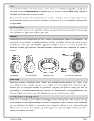
  • 1. Yatin Kumar Singh Page 1 Gears Gears are toothed members which transmit power / motion between two shafts by meshing without any slip. Hence, gear drives are also called Positive Drives. In any pair of gears, the smaller one is called Pinion and the larger one is called Gear immaterial of which is driving the other. When pinion is the driver, it results in step down drive in which the output speed decreases and the torque increases. On the other hand, when the gear is the driver, it results in step up drive in which the output speed increases and the torque decreases. Classification of Gears Gears are classified according to the shape of the tooth pair and disposition into spur, helical, double helical, straight bevel, spiral bevel and hypoid bevel, worm and spiral gears. Spur Gears Spur gears have their teeth parallel to the axis and are used for transmitting power between two parallel shafts. They are simple in construction, easy to manufacture and cost less. They have highest efficiency and excellent precision rating. They are used in high speed and high load application in all types of trains and a wide range of velocity ratios. Hence, they find wide applications right from clocks, household gadgets, motor cycles, automobiles, and railways to aircrafts. (a) Spur Gear (b) Helical Gear (c) Internal Gear (d) Worm and Worm Gear Helical Gears Helical gears are used for parallel shaft drives. They have teeth inclined to the axis as shown in Fig. 1.9. Hence for the same width, their teeth are longer than spur gears and have higher load carrying capacity. Their contact ratio is higher than spur gears and they operate smoother and quieter than spur gears. Their precision rating is good. They are recommended for very high speeds and loads. Thus, these gears find wide applications in automotive gearboxes. Their efficiency is slightly lower than spur gears. The helix angle also introduces axial thrust on the shaft. Double Helical Gear or Herringbone Gear Double helical or Herringbone gears used for transmitting power between two parallel shafts. They have opposing helical teeth with or without a gap depending on the manufacturing method adopted. Two axial thrusts oppose each other and nullify. Hence the shaft is free from any axial force. Though their load capacity is very high, manufacturing difficulty makes them costlier than single helical gear. Their applications are limited to high capacity reduction drives like that of cement mills and crushers.
  • 2. Yatin Kumar Singh Page 2 Internal Gear Internal gears are used for transmitting power between two parallel shafts. In these gears, annular wheels are having teeth on the inner periphery. This makes the drive very compact. In these drives, the meshing pinion and annular gear are running in the same direction. Their precision rating is fair. They are useful for high load and high speed application with high reduction ratio. Applications of these gears can be seen in planetary gear drives of automobile automatic transmissions, reduction gearboxes of cement mills, step-up drives of wind mills. They are not recommended for precision meshes because of design, fabrication, and inspection limitations. They should only be used when internal feature is necessary. However, today precision machining capability has led to their usage even in position devices like antenna drives. Rack and Pinion Rack is a segment of a gear of infinite diameter. The tooth can be spur or helical. This type of gearing is used for converting rotary motion into translatory motion or visa versa. Rack and Pinion Double Helical Gear Straight Bevel Gear Straight bevel gears are used for transmitting power between intersecting shafts. They can operate under high speeds and high loads. Their precision rating is fair to good. They are suitable for 1:1 and higher velocity ratios and for right- angle meshes to any other angles. Their good choice is for right angle drive of particularly low ratios. However, complicated both form and fabrication limits achievement of precision. They should be located at one of the less critical meshes of the train. Wide application of the straight bevel drives is in automotive differentials, right angle drives of blenders and conveyors. Spiral Bevel Gear Spiral bevel gears are also used for transmitting power between intersecting shafts. Because of the spiral tooth, the contact length is more and contact ratio is more. They operate smoother than straight bevel gears and have higher load capacity. But, their efficiency is slightly lower than straight bevel gear. Hypoid Bevel Gear These gears are also used for right angle drive in which the axes do not intersect. This permits the lowering of the pinion axis which is an added advantage in automobile in avoiding hump inside the automobile drive line power transmission. However, the non – intersection introduces a considerable amount of sliding and the drive requires good lubrication to reduce the friction and wear. Their efficiency is lower than other two types of bevel gears. These gears are widely used in current day automobile drive line power transmission.
  • 3. Yatin Kumar Singh Page 3 Straight Bevel Gear Hypoid Bevel Gear Spiral Gear Worm Gear Worm and worm gear pair consists of a worm, which is very similar to a screw and a worm gear, which is a helical gear. They are used in right-angle skew shafts. In these gears, the engagement occurs without any shock. The sliding action prevalent in the system while resulting in quieter operation produces considerable frictional heat. High reduction ratios 8 to 400 are possible. Efficiency of these gears is low anywhere from 90% to 40 %. Higher speed ratio gears are non-reversible. Their precision rating is fair to good. They need good lubrication for heat dissipation and for improving the efficiency. The drives are very compact. Worm gearing finds wide application in material handling and transportation machinery, machine tools, automobiles etc. Spiral Gear Spiral gears are also known as crossed helical gears. They have high helix angle and transmit power between two non- intersecting non-parallel shafts. They have initially point contact under the conditions of considerable sliding velocities finally gears will have line contact. Hence, they are used for light load and low speed application such as instruments, sewing machine etc. Their precision rating is poor. Characteristics of Gears Spur Gear:  The teeth are straight and parallel to the shaft axis.  Transmits power and motion between rotating two parallel shafts. Features:  Easy to manufacture  There are no axial force  Relatively easy to produce high-quality gears  The most common type of gear Applications:  Transmission components Helical Gear:  The teeth are twisted oblique to the gear axis. Helix Direction (Helix Hand):  The hand of helix is designated as either left or right  Right-hand and left-hand helical gears mate as a set. But they must have the same helix angle
  • 4. Yatin Kumar Singh Page 4 Features:  Has higher strength compared with a spur gear  More effective in reducing noise and vibration when compared with a spur gear  Gears in mesh produce thrust forces in the axial direction Applications:  Transmission components, automobile, speed reducers, etc. Gear Rack:  The rack is a bar containing teeth on one face for meshing with a gear.  The basic rack form is the profile of a gear of infinite diameter.  Racks with machined ends can be joined together to make any desired length. Features:  Changes a rotary motion into a rectilinear motion and vice versa Applications:  A transfer system for machine tools, printing presses, robots, etc. Internal Gear:  An annular gear having teeth on the inner surface of its rim.  The internal gear always meshes with an external gear. Features:  When meshing two external gears, the rotation occurs in the opposite directions. When meshing an internal gear with an external gear the rotation occurs in the same direction  Care should be taken with regard to the number of teeth on each gear when meshing a large (internal) gear with a small (external) gear, since three types of interference can occur  Usually internal gears are driven by small external gears  Allows for a compact design of the machine Applications:  Planetary gear drive of high reduction ratios, clutches, etc.
  • 5. Yatin Kumar Singh Page 5 Bevel Gear: Picture: Bevel gear, apex and pitch cone One of a pair of gears used to connect two shafts whose axes intersect, and the pitch surfaces are cones. Teeth are cut along the pitch cone. Depending on tooth trace, bevel gear is classified as: 1. Straight Bevel Gear 2. Spiral Bevel Gear Straight Bevel Gear Spiral Bevel Gear Miter Gear Straight Bevel Gear:  A simple form of bevel gear having straight teeth which, if extended inward, would come together at the intersection of the shaft axes. Features:  Relatively easy to manufacture  Provides reduction ratios up to approx. 1:5 Applications:  Machine tools, printing presses, etc. Especially suitable for use as a differential gear unit Spiral Bevel Gear:  Bevel gear with curved, oblique teeth to provide gradual engagement and larger contact surface at a given time than an equivalent straight bevel gear. Features:  Has higher contact ratio, higher strength and durability than an equivalent straight bevel gear  Allows a higher reduction ratio
  • 6. Yatin Kumar Singh Page 6  Has better efficiency of transmission with reduced gear noise  Involves some technical difficulties in manufacturing Applications:  Automobiles, tractors, vehicles, final reduction gearing for ships. Especially suitable for high-speed, heavy load drives Miter Gears:  A special class of bevel gear where the shafts intersect at 90° and the gear ratio is 1:1.  It is used to change the direction of shaft rotation without change in speed. Screw Gear Worm, Worm Gear and Center distance Screw Gear: A helical gear that transmits power from one shaft to another, nonparallel, nonintersecting shaft Features:  Can be used as a speed reducer or as a speed increaser  Due to sliding contact, has higher friction  Not suitable for transmission of high horsepower Applications:  Driving gear for automobile. Automatic machines that require intricate movement Worm Gear:  Worm is a shank having at least one complete tooth (thread) around the pitch surface and is the driver of a worm wheel.  Worm Gear (worm wheel) is a gear with teeth cut on an angle to be driven by a worm.  The worm gear pair is used to transmit motion between two shafts which are at 90°to each other and lie on a plane. Features:  Provides large reduction ratios for a given center distance  Quiet and smooth meshing action  It is not possible for a worm wheel to drive a worm unless certain conditions are met Applications:  Speed reducers, anti reversing gear devices making the most of its self-locking features, machine tools, indexing devices, chain blocks, portable generators, etc.
  • 7. Yatin Kumar Singh Page 7 Nomenclature The Pitch Circle is a theoretical circle upon which all calculations are usually based; its diameter is the pitch diameter. The pitch circles of a pair of mating gears are tangent to each other. A pinion is the smaller of two mating gears. The larger is often called the gear. The Circular Pitch p is the distance, measured on the pitch circle, from a point on one tooth to a corresponding point on an adjacent tooth. Thus the circular pitch is equal to the sum of the tooth thickness and the width of space. The Module m is the ratio of the pitch diameter to the number of teeth. The customary unit of length used is the millimeter. The module is the index of tooth size in SI. The Diametral Pitch P is the ratio of the number of teeth on the gear to the pitch diameter. Thus, it is the reciprocal of the module. Since diametral pitch is used only with U.S. units, it is expressed as teeth per inch. The Addendum a is the radial distance between the top land and the pitch circle. The Dedendum b is the radial distance from the bottom land to the pitch circle. The whole depth ht is the sum of the addendum and the dedendum.
  • 8. Yatin Kumar Singh Page 8 The Clearance Circle is a circle that is tangent to the addendum circle of the mating gear. The clearance c is the amount by which the dedendum in a given gear exceeds the addendum of its mating gear. The Backlash is the amount by which the width of a tooth space exceeds the thickness of the engaging tooth measured on the pitch circles. = − = − = � = � − = � − where P = diametral pitch, teeth per inch; N = number of teeth; d = pitch diameter, in; m = module, mm; d = pitch diameter, mm; p = circular pitch Involute Gear This figure indicates how two involute teeth in mesh are moving to transmit rotary motion. Rotational sequence of the gears: P1- P2- P3 When Gear 1 drives Gear 2 by acting at the instantaneous contact point, the contact point moves on the common tangent in the order of P1- P2- P3. The contact point rolls along the involute curves of the gears. Moreover, the points P1, P2 and P3 lie on the common tangent to the two base circles. It is similar to the point, P, on a criss-crossed belt as the disks rotate. In effect, the involute shape of the gear teeth allows the contact point to move smoothly, transmitting the motion. Therefore, the involute curve is the ideal shape for gear teeth. Features:  Conjugate action is relatively independent of small errors in center distance  Can be manufactured at low cost since the tooth profile is relatively simple  Its root thickness makes it strong  A typical tooth profile used almost exclusively for gears.
  • 9. Yatin Kumar Singh Page 9 Law of Gearing The fundamental law of gearing states that the angular velocity ratio between the gears of a gear set must remain constant throughout the mesh. This amounts to the following relationship: � � = = = In order to maintain constant angular velocity ratio between two meshing gears, the common normal of the tooth profiles, at all contact points with in mesh, must always pass through a fixed point on the line of centers, called pitch point. Profiles Satisfying Law of Gears Profiles which can satisfy the law of gearing are shown in Fig. a to c. These are (a) involute (b) cycloidal and (c) circular arc or Novikov. Among these, cycloidal was the first to be evolved. This is followed by the invention of involute profile which replaced many of the other profiles due to several technological advantages. Circular arc or Novikov profile has some advantages over the other profiles. But due to manufacturing difficulties, it did not become popular. However with powder metallurgy process it is slowly getting into industry now for specific application. Fig. Profiles satisfying the law of gearing, (a) involute (b) cycloidal and (c) Circular arc Fig.1.23 The generation of involute profile on right side Fig.1.24 The generation of involute profile on left side Involute Gear Tooth Profile Involute is the path generated by the end of a thread as it unwinds from a reel. In order to understand what is involute, imagine a reel with thread wound in the clockwise direction as in Fig. Tie a knot at the end of the thread. In the initial position, the thread is at B0 with knot on the reel at C0. Keeping the reel stationary, pull the thread and
  • 10. Yatin Kumar Singh Page 10 unwind it to position B1. The knot now moves from C0 to C1. If the thread is unwound to position B2 the knot moves to C2 position. In repeated unwinding, the taut thread occupies position B3, B4 while the knot moves to C3, C4 positions. Connect these points C0 to C4 by a smooth curve, the profile obtained is nothing but an involute, the illustration of which is given below. This forms the left side part of the tooth profile. If similar process is repeated with thread wound on the reel in anticlockwise direction in the same position, it forms the right side part of the same tooth. The completely formed involute tooth is shown in Fig. Fig.1.25 Involute gear tooth profile appearance after generation Fig. 1.26 Gear meshing Involute profiles have special properties. Imagine two involute teeth in contact as shown in Fig.1.26. If a normal is drawn at the contact point to the involute profile, it will be tangent to the generating circles. This can be visualized better from Fig. 1.23 where the taut thread is normal to the profile as well as tangent to the reel which forms the generating or the base circle. The profile will be involute above the base circle only. Below the base circle the profile will not be involute. The common normal to the profile at the contact point will be tangent to the base circles. It passes through a fixed point lying at the intersection of the tangent to the rolling/pitch circles and the line connecting the centres of the gear wheels. This point is known as the pitch point. As the gears rotate the contact point travels along the common tangent to the base circle. Hence this line is also known as the line of action. The movement of the contact point along the line of action can be seen in the gear meshing later on. Advantages of Involute Gears 1. Variation in centre distance does not affect the velocity ratio. 2. Pressure angle remains constant throughout the engagements which results in smooth running. 3. Straight teeth of basic rack for involute admit simple tools. Hence, manufacturing becomes simple and cheap. Cycloidal Gear Tooth Profile Cycloid is the locus of a point on the circumference of a circle when it rolls on a straight line without slipping. If the circle rolls on the outside of another circle or inside of another circle gives rise to epicycloid and hypocycloid respectively. This is illustrated in Fig. 1.27. The profile of a cycloidal tooth consists of two separate curves or double curvature. This tooth form also satisfies the law of gearing or conjugate action similar to an involute gear.
  • 11. Yatin Kumar Singh Page 11 Fig.1.27 Figure illustrating the generation of cycloidal tooth Fig.1.28 Cycloidal tooth form Advantages of Cycloidal Gears 1. Cycloidal gears do not have interference. 2. Cycloidal tooth is generally stronger than an involute tooth owing to spreading flanks in contrast to the radial flanks of an involute tooth. 3. Because of the spreading flanks, they have high strength and compact drives are achievable. 4. Cycloidal teeth have longer life since the contact is mostly rolling which results in low wear. Disadvantages of Cycloidal Gears 1. For a pair of Cycloidal gears, there is only one theoretically correct center distance for which a constant angular- velocity ratio is possible. 2. The hob of Cycloidal gear has curved teeth unlike involute rack teeth. Hence hob manufacture is difficult and costly. 3. Cycloidal gear will cost more. Applications of Cycloidal Gears 1. Cycloidal gears are extensively used in watches, Clocks, and instruments where strength and interference are prime considerations. 2. Cast bull gears of paper mill machinery. 3. Crusher drives in sugar mills.
  • 12. Yatin Kumar Singh Page 12 Pressure Angle The pressure angle exists between the tooth profile and a radial line to its pitch point. In involute teeth, it is defined as the angle formed by the radial line and the line tangent to the profile at the pitch point. Here α = α . Therefore, α is also the pressure angle. 1. Normal to the profile 2. Tangent to the reference circle 3. Tangent to the profile 4. Radial line
  • 13. Yatin Kumar Singh Page 13 This figure indicates the meshing of a gear A and a gear B at the pitch point. 1.Common normal 2.Reference circle 3.Reference circle At the pitch point, the gear A is pushing the gear B. The pushing force acts along the common normal of the gear A and the gear B. The pressure angle can be described as the angle between the common normal and the line tangent to the reference circle. The most common pressure angle is 20°. Formerly, a pressure angle of 14.5° was also used. Forms of Teeth In actual practice, following are the two types of teeth commonly used. 1. Cycloidal Teeth; and 2. Involute Teeth Cycloidal Teeth A cycloid is the curve traced by a point on the circumference of a circle which rolls without slipping on a fixed straight line. When a circle rolls without slipping on the outside of a fixed circle, the curve traced by a point on the circumference of a circle is known as epicycloid. On the other hand, if a circle rolls without slipping on the inside of a fixed circle, then the curve traced by a point on the circumference of a circle is called hypocycloid. (a) (b) Figure 1.8 Construction of cycloidal teeth of a gear In Fig. 1.8 (a), the fixed line or pitch line of a rack is shown. When the circle C rolls without slipping above the pitch line in the direction as indicated in Fig. 1.8 (a), then the point P on the circle traces the epicycloid PA. This represents the face of the cycloidal tooth profile. When the circle D rolls without slipping below the pitch line, then the point P on
  • 14. Yatin Kumar Singh Page 14 the circle D traces hypocycloid PB which represents the flank of the cycloidal tooth. The profile BPA is one side of the cycloidal rack tooth. Similarly, the two curves P' A' and P' B' forming the opposite side of the tooth profile are traced by the point P' when the circles C and D roll in the opposite directions. In the similar way, the cycloidal teeth of a gear may be constructed as shown in Fig. 1.8 (b). The circle C is rolled without slipping on the outside of the pitch circle and the point P on the circle C traces epicycloid PA, which represents the face of the cycloidal tooth. The circle D is rolled on the inside of pitch circle and the point P on the circle D traces hypocycloid PB, which represents the flank of the tooth profile. The profile BPA is one side of the cycloidal tooth. Figure 1.9 Construction of two mating cycloidal teeth The construction of the two mating cycloidal teeth is shown in Fig. 1.9. A point on the circle D will trace the flank of the tooth T1 when circle D rolls without slipping on the inside of pitch circle of wheel 1 and face of tooth T2 when the circle D rolls without slipping on the outside of pitch circle of wheel 2. Similarly, a point on the circle C will trace the face of tooth T1 and flank of tooth T2. The rolling circles C and D may have unequal diameters, but if several wheels are to be interchangeable, they must have rolling circles of equal diameters. A little consideration will show that the common normal XX at the point of contact between two cycloidal teeth always passes through the pitch point, which is the fundamental condition for a constant velocity ratio. Involute Teeth An involute of a circle is a plane curve generated by a point on a tangent, which rolls on the circle without slipping or by a point on a taut string which is unwrapped from a reel as shown in Fig. 1.10 (a). In connection with toothed wheels, the circle is known as base circle. The involute is traced as follows:
  • 15. Yatin Kumar Singh Page 15 Let A be the starting point of the involute. The base circle is divided into equal number of parts e.g. AP1, P1 P2, P2 P3 etc. The tangents at P1, P2, P3 etc., are drawn and the lengths P1A1, P2A2, P3A3 equal to the arcs AP1, AP2 and AP3 are set off. Joining the points A, A1, A2, A3 etc., we obtain the involute curve AR. A little consideration will show that at any instant A3, the tangent A3T to the involute is perpendicular to P3A3 and P3A3 is the normal to the involute. In other words, normal at any point of an involute is a tangent to the circle. Now, let O1 and O2 be the fixed centres of the two base circles as shown in Fig. 1.10(b). Let the corresponding involutes AB and A'B' be in contact at point Q. MQ and NQ are normals to the involute at Q and are tangents to base circles. Since the normal for an involute at a given point is the tangent drawn from that point to the base circle, therefore the common normal MN at Q is also the common tangent to the two base circles. We see that the common normal MN intersects the line of centres O1O2 at the fixed point P (called pitch point). Therefore the involute teeth satisfy the fundamental condition of constant velocity ratio. From similar triangles O2NP and O1MP, = = � � � which determines the ratio of the radii of the two base circles. The radii of the base circles is given by = � an� = � where φ is the pressure angle or the angle of obliquity. � = + = � + � = + � If the centre distance is changed, then the radii of pitch circles also changes. But their ratio remains unchanged, because it is equal to the ratio of the two radii of the base circles. The common normal, at the point of contact, still passes through the pitch point. As a result of this, the wheel continues to work correctly (It is not the case with cycloidal teeth). However, the pressure angle increases with the increase in centre distance. Systems of Gear Teeth The following four systems of gear teeth are commonly used in practice. 1. 14 1/2° Composite System, 2. 14 1/2° Full Depth Involute System 3. 20° Full Depth Involute 4. 20° Stub Involute System The 14 1/2° composite system is used for general purpose gears. It is stronger but has no interchangeability. The tooth profile of this system has cycloidal curves at the top and bottom and involute curve at the middle portion. The teeth are produced by formed milling cutters or hobs. The tooth profile of the 14 1/2° full depth involute system was developed for use with gear hobs for spur and helical gears. The tooth profile of the 20° full depth involute system may be cut by hobs. The increase of the pressure angle from 14 1/2° to 20° results in a stronger tooth, because the tooth acting as a beam is wider at the base. The 20° stub involute system has a strong tooth to take heavy loads.
  • 16. Yatin Kumar Singh Page 16 Condition for Constant Velocity Ratio of Gears–Law of Gearing Consider the portions of the two teeth, one on the wheel 1 (or pinion) and the other on the wheel 2, as shown by thick line curves in Fig. 1.7. Let the two teeth come in contact at point Q, and the wheels rotate in the directions as shown in the figure. Let TT be the common tangent and MN be the common normal to the curves at point of contact Q. From the centres O1 and O2, draw O1M and O2N perpendicular to MN. A little consideration will show that the point Q moves in the direction QC, when considered as a point on wheel 1, and in the direction QD when considered as a point on wheel 2. Let v1 and v2 be the velocities of the point Q on the wheels 1 and 2 respectively. If the teeth are to remain in contact, then the components of these velocities along the common normal MN must be equal. Figure 1.7 Law of Gearing ∴ = � × = � × � × = � × ∴ � = �
  • 17. Yatin Kumar Singh Page 17 ∴ � � = � Also from similar triangles O1MP and O2NP, = �� Combining equations (i) and (ii), we have � � = = ��� We see that the angular velocity ratio is inversely proportional to the ratio of the distance of P from the centres O1 and O2, or the common normal to the two surfaces at the point of contact Q intersects the line of centres at point P which divides the centre distance inversely as the ratio of angular velocities. Therefore, in order to have a constant angular velocity ratio for all positions of the wheels, P must be the fixed point (called Pitch Point) for the two wheels. In other words, the common normal at the point of contact between a pair of teeth must always pass through the pitch point. This is fundamental condition which must be satisfied while designing the profiles for the teeth of gear wheels. It is also known as Law of Gearing. Notes: 1. The above condition is fulfilled by teeth of involute form, provided that the root circles from which the profiles are generated are tangential to the common normal. 2. If the shape of one tooth profile is arbitrary chosen and another tooth is designed to satisfy the above condition, then the second tooth is said to be conjugate to the first. The conjugate teeth are not in common use because of difficulty in manufacture and cost of production. 3. If D1 and D2 are pitch circle diameters of wheel 1 and 2 having teeth T1 and T2 respectively, then velocity ratio, � � = = = Interference in Involute Gears A pinion gearing with a wheel is shown in Fig. 1.11. MN is the common tangent to the base circles and KL is the path of contact between the two mating teeth. A little consideration will show that if the radius of the addendum circle of pinion is increased to O1N, the point of contact L will move from L to N. When this radius is further increased, the point of contact L will be on the inside of base circle of wheel and not on the involute profile of tooth on wheel. The tip of tooth on the pinion will then undercut the tooth on the wheel at the root and remove part of the involute profile of tooth on the wheel. This effect is known as Interference and occurs when the teeth are being cut. In brief, the phenomenon when the tip of a tooth undercuts the root on its mating gear is known as interference. Similarly, if the radius of the addendum circle of the wheel increases beyond O2M, then the tip of tooth on wheel will cause interference with the tooth on pinion. The points M and N are called interference points. Obviously interference may be avoided if the path of contact does not extend beyond interference points. The limiting value of the radius of the addendum circle of the pinion is O1N and of the wheel is O2M. From the above discussion, we conclude that the interference may only be avoided, if the point of contact between the two teeth is always on the involute profiles of both the teeth. In other words, interference may only be prevented, if the addendum circles of the two mating gears cut the common tangent to the base circles between the points of tangency.
  • 18. Yatin Kumar Singh Page 18 Note: In order to avoid interference, the limiting value of the radius of the addendum circle of the pinion (O1N) and of the wheel (O2M), may be obtained as follows: From Fig. 1.11, we see that = √ + = √ + [ + �] w����, = � = � = � = √ + = √ + [ + �] w����, = � � = � = � Figure 1.11 Interference in involute gears Minimum Number of Teeth on the Pinion in Order to Avoid Interference Interference may only be avoided, if the point of contact between the two teeth is always on the involute profiles of both the teeth. The number of teeth on the pinion (TP) in order to avoid interference may be obtained from the following relation: = � [√ + + � − ] where AW = Fraction by which the standard addendum for the wheel should be multiplied, G = Gear ratio or velocity ratio = TG / TP = DG / DP, φ = Pressure angle or angle of obliquity.
  • 19. Yatin Kumar Singh Page 19 Contact Ratio The zone of action of meshing gear teeth is shown in Fig. 1–15. We recall that tooth contact begins and ends at the intersections of the two addendum circles with the pressure line. In Fig. 1–15 initial contact occurs at a and final contact at b. Tooth profiles drawn through these points intersect the pitch circle at A and B, respectively. As shown, the distance AP is called the arc of approach qa , and the distance PB, the arc of recess qr . The sum of these is the arc of action qt . Now, consider a situation in which the arc of action is exactly equal to the circular pitch, that is, qt = p. This means that one tooth and its space will occupy the entire arc AB. In other words, when a tooth is just beginning contact at a, the previous tooth is simultaneously ending its contact at b. Therefore, during the tooth action from a to b, there will be exactly one pair of teeth in contact. Figure 1-15 Definition of contact ratio Next, consider a situation in which the arc of action is greater than the circular pitch, but not very much greater, say, qt = 1.2p. This means that when one pair of teeth is just entering contact at a, another pair, already in contact, will not yet have reached b. Thus, for a short period of time, there will be two teeth in contact, one in the vicinity of A and another near B. As the meshing proceeds, the pair near B must cease contact, leaving only a single pair of contacting teeth, until the procedure repeats itself. Because of the nature of this tooth action, either one or two pairs of teeth in contact, it is convenient to define the term contact ratio mc as = − a number that indicates the average number of pairs of teeth in contact. Note that this ratio is also equal to the length of the path of contact divided by the base pitch. Gears should not generally be designed having contact ratios less than about 1.20, because inaccuracies in mounting might reduce the contact ratio even more, increasing the possibility of impact between the teeth as well as an increase in the noise level. An easier way to obtain the contact ratio is of action ab instead of the arc distance AB. Since ab in Fig. 1–15 is tangent to the base circle when extended, the base to measure the line pitch pb must be used to calculate mc instead of the circular pitch as in Eq. (1–8). If the length of the line of action is Lab, the contact ratio is
  • 20. Yatin Kumar Singh Page 20 = � − in which Eq. (1–7) was used for the base pitch. Interference The contact of portions of tooth profiles that are not conjugate is called Interference. Consider Fig. 1–16. Illustrated are two 16-tooth gears that have been cut to the now obsolete 14½0 pressure angle. The driver, gear 2, turns clockwise. The initial and final points of contact are designated A and B, respectively, and are located on the pressure line. Now notice that the points of tangency of the pressure line with the base circles C and D are located inside of points A and B. Interference is present. Figure 1-16 The interference is explained as follows. Contact begins when the tip of the driven tooth contacts the flank of the driving tooth. In this case the flank of the driving tooth first makes contact with the driven tooth at point A, and this occurs before the involute portion of the driving tooth comes within range. In other words, contact is occurring below
  • 21. Yatin Kumar Singh Page 21 the base circle of gear 2 on the non-involute portion of the flank. The actual effect is that the involute tip or face of the driven gear tends to dig out the non-involute flank of the driver. In this example the same effect occurs again as the teeth leave contact. Contact should end at point D or before. Since it does not end until point B, the effect is for the tip of the driving tooth to dig out, or interfere with, the flank of the driven tooth. When gear teeth are produced by a generation process, interference is automatically eliminated because the cutting tool removes the interfering portion of the flank. This effect is called Undercutting; if undercutting is at all pronounced, the undercut tooth is considerably weakened. Thus the effect of eliminating interference by a generation process is merely to substitute another problem for the original one. The smallest number of teeth on a spur pinion and gear, one-to-one gear ratio, which can exist without interference is NP . This number of teeth for spur gears is given by = � � + √ + � − where k = 1 for full-depth teeth, 0.8 for stub teeth and φ = pressure angle. For a 20◦ pressure angle, with k = 1, = ° + √ + ° = . = Thus 13 teeth on pinion and gear are interference-free. Realize that 12.3 teeth is possible in meshing arcs, but for fully rotating gears, 13 teeth represents the least number. For a 14½0 pressure angle, NP = 23 teeth, so one can appreciate why few 14½0 tooth systems are used, as the higher pressure angles can produce a smaller pinion with accompanying smaller center-to-center distances. If the mating gear has more teeth than the pinion, that is, mG = NG/NP = m is more than one, then the smallest number of teeth on the pinion without interference is given by = � + � + √ + + � − For example, if m = 4, φ = 20◦ = ( + ) ° + √ + ( + ) ° = . = Thus a 16-tooth pinion will mesh with a 64-tooth gear without interference. The largest gear with a specified pinion that is interference-free is = � − − ° = . = For example, for a 13-tooth pinion with a pressure angle φ of 20◦, = ° − � � − � − For a 13-tooth spur pinion, the maximum number of gear teeth possible without interference is 16.
  • 22. Yatin Kumar Singh Page 22 The smallest spur pinion that will operate with a rack without interference is = � � − For a 20◦ pressure angle full-depth tooth the smallest number of pinion teeth to mesh with a rack is = ° = . = Since gear-shaping tools amount to contact with a rack, and the gear-hobbing process is similar, the minimum number of teeth to prevent interference to prevent undercutting by the hobbing process is equal to the value of NP when NG is infinite. The importance of the problem of teeth that have been weakened by undercutting cannot be overemphasized. Of course, interference can be eliminated by using more teeth on the pinion. However, if the pinion is to transmit a given amount of power, more teeth can be used only by increasing the pitch diameter. Interference can also be reduced by using a larger pressure angle. This results in a smaller base circle, so that more of the tooth profile becomes involute. The demand for smaller pinions with fewer teeth thus favors the use of a 250 pressure angle even though the frictional forces and bearing loads are increased and the contact ratio decreased. Undercutting Interference can also be avoided by removing the material on the gear tooth between the base circle and dedendum circle. This is the portion of the gear tooth that is not an involute and would interfere with the mating tooth. An undercut gear tooth is shown in Figure. Undercutting obviously reduces the strength of the gear, thus reducing the power that can be safely transmitted. In addition, it also reduces the length of contact, which reduces the contact ratio and results in rougher and noisier gear action. Therefore, undercutting should be avoided unless the application absolutely requires a compact gearset. In these cases, advanced kinematic and strength analyses and experiments are necessary to verify proper operation. Fig. Undercut gear tooth Backlash Backlash is the amount that the width of a tooth space exceeds the thickness of a gear tooth, measured on the pitch circle. In more practical terms, it is the amount that a gear can turn without its mating gear turning. Although backlash may seem undesirable, some backlash is necessary to provide for lubrication on the gear teeth. Gears that run
  • 23. Yatin Kumar Singh Page 23 continuously in one direction can actually have considerable backlash. Gears that frequently start/stop or reverse direction should have closely controlled backlash. A nominal value of backlash is designed into a gear tooth profile. The amount of backlash determines the thickness of a gear tooth because backlash is a measure of the tooth thickness to the tooth space. Backlash values are strongly influenced by any variation in the center distance of the gears. Gears Trains A gear train is two or more gear working together by meshing their teeth and turning each other in a system to generate power and speed. It reduces speed and increases torque. To create large gear ratio, gears are connected together to form gear trains. They often consist of multiple gears in the train. The most common of the gear train is the gear pair connecting parallel shafts. The teeth of this type can be spur, helical or herringbone. The angular velocity is simply the reverse of the tooth ratio. Any combination of gear wheels employed to transmit motion from one shaft to the other is called a Gear Train. The meshing of two gears may be idealized as two smooth discs with their edges touching and no slip between them. This ideal diameter is called the Pitch Circle Diameter (PCD) of the gear. Simple Gear Trains The typical spur gears as shown in diagram. The direction of rotation is reversed from one gear to another. It has no affect on the gear ratio. The teeth on the gears must all be the same size so if gear A advances one tooth, so does B and C. t = number of teeth on the gear; N = speed in rpm; Module must be the same for all gears otherwise they would not mesh. = = = L�n�a� ��loc��� on ��� c��cl�, = �. = � The velocity v of any point on the circle must be the same for all the gears, otherwise they would be slipping. = � = � = � � = � = �
  • 24. Yatin Kumar Singh Page 24 � = � = � � = � = � o� �n ���m� o� ��� m�n⁄ = = Application a) To connect gears where a large center distance is required b) To obtain desired direction of motion of the driven gear (CW or CCW) c) To obtain high speed ratio Torque & Efficiency The power transmitted by a torque T N-m applied to a shaft rotating at N rev/min is given by: = � In an ideal gear box, the input and output powers are the same so; = � = � = ⇒ = = It follows that if the speed is reduced, the torque is increased and vice versa. In a real gear box, power is lost through friction and the power output is smaller than the power input. The efficiency is defined as: � = � = � � = Because the torque in and out is different, a gear box has to be clamped in order to stop the case or body rotating. A holding torque T3 must be applied to the body through the clamps. The total torque must add up to zero. T1 + T2 + T3 = 0 If we use a convention that anti-clockwise is positive and clockwise is negative we can determine the holding torque. The direction of rotation of the output shaft depends on the design of the gear box. Compound Gear Train Compound gears are simply a chain of simple gear trains with the input of the second being the output of the first. A chain of two pairs is shown below. Gear B is the output of the first pair and gear C is the input of the second pair. Gears B and C are locked to the same shaft and revolve at the same speed. For large velocities ratios, compound gear train arrangement is preferred.
  • 25. Yatin Kumar Singh Page 25 The velocity of each tooth on A and B are the same so: ωA tA =ωB tB -as they are simple gears. Likewise for C and D, ωC tC = ωD tD. � = � an� � = � � × � � × � = × ��nc� ��a� B an� C a�� on ��� �am� ��a�� �o � = � � � = × = ��nc� � = × � × ��� ��a� �a��o ma� b� w�����n a� � = × = Reverted Gear train The driver and driven axes lies on the same line. These are used in speed reducers, clocks and machine tools. = = × × If R and T= Pitch circle radius & number of teeth of the gear + = + + = + Epicyclic Gear Train Epicyclic means one gear revolving upon and around another. The design involves planet and sun gears as one orbits the other like a planet around the sun. This design can produce large gear ratios in a small space and are used on a wide range of applications from marine gearboxes to electric screwdrivers. Basic Theory: The diagram shows a gear B on the end of an arm. Gear B meshes with gear C and revolves around it when the arm is rotated. B is called the planet gear and C the sun. First consider what happens when the planet gear orbits the sun gear. Observe point p and you will see that gear B also revolves once on its own axis. Any object orbiting around a center must rotate once. Now consider that B is free to rotate on its shaft and meshes with C. Suppose the arm is held
  • 26. Yatin Kumar Singh Page 26 stationary and gear C is rotated once. B spins about its own center and the number of revolutions it makes is the ratio tC /tB B will rotate by this number for every complete revolution of C. Now consider that C is unable to rotate and the arm A is revolved once. Gear B will revolve (1+ tC/tB) because of the orbit. It is this extra rotation that causes confusion. One way to get round this is to imagine that the whole system is revolved once. Then identify the gear that is fixed and revolve it back one revolution. Work out the revolutions of the other gears and add them up. The following tabular method makes it easy. Suppose gear C is fixed and the arm A makes one revolution. Determine how many revolutions the planet gear B makes. Step 1 is to revolve everything once about the center. Step 2 identify that C should be fixed and rotate it backwards one revolution keeping the arm fixed as it should only do one revolution in total. Work out the revolutions of B. Step 3 is simply add them up and we find the total revs of C is zero and for the arm is 1. ��� n�mb�� o� ���ol���on� ma�� b� B �� ( + )
  • 27. Yatin Kumar Singh Page 27 Problem 1: In an epicyclic gear train shown in figure, the arm A is fixed to the shaft S. The wheel B having 100 teeth rotates freely on the shaft S. The wheel F having 150 teeth is driven separately. If the arm rotates at 200 rpm and wheel F at 100 rpm in the same direction; find (a) number of teeth on the gear C and (b) speed of wheel B. Solution: TB =100; TF =150; NA = 200rpm; NF =100rpm: Since the module is same for all gears the number of teeth on the gears is proportional to the pitch circle: � = � + � ; � = � + � = + × � o� � = The gear B and gear F rotates in the opposite directions: ��a�n Val�� = − � � Al�o ��a�n Val�� = �� − � �� � − � �� = � − � � − � − � � = � − � � − � ; − = − � − ⇒ = The Gear B rotates at 350 rpm in the same direction of gears F and Arm A. Problem 2: In a compound epicyclic gear train as shown in the figure, has gears A and an annular gears D & E free to rotate on the axis P. B and C is a compound gear rotate about axis Q. Gear A rotates at 90 rpm CCW and gear D rotates at 450 rpm CW. Find the speed and direction of rotation of arm F and gear E. Gears A,B and C are having 18, 45 and 21 teeth respectively. All gears having same module and pitch.
  • 28. Yatin Kumar Singh Page 28 Solution: TA=18 ; TB=45; TC=21; NA = -90rpm; ND=450rpm Since the module and pitch are same for all gears; the number of teeth on the gears is proportional to the pitch circle: = + + ⇒ = + + ; = + + = Gears A and D rotates in the opposite directions. ��a�n Val�� = − � � × � � Al�o ��a�n Val�� = �� − � �� � − � �� = � − � � − � − � � × � � = � − � � − � ; − × × = − � − − � ⇒ = = . � Now consider gears A, B and E: � = � + � ⇒ � = � + � + � ; � = + × = Gears A and E rotates in the opposite directions: ��a�n Val�� = − � � Al�o ��a�n Val�� = � − � � − � − � � = � − � � − � ; − = � − . − − . ⇒ = . � Problem 3: In an epicyclic gear of sun and planet type shown in figure, the pitch circle diameter of the annular wheel A is to be nearly 216mm and module 4mm. When the annular ring is stationary, the spider that carries three planet wheels P of equal size, to make, one revolution for every five revolution of the driving spindle carrying the sun wheel. Determine the number of teeth for all the wheels and the exact pitch circle diameter of the annular wheel. If an input torque of 20 N-m is applied to the spindle carrying the sun wheel, determine the fixed torque on the annular wheel. Solution: Module being the same for all the meshing gears: = + = = =
  • 29. Yatin Kumar Singh Page 29 If L rotates +1 revolution: so n = 1 (1) The sun wheel S to rotate +5 revolutions correspondingly: n + m = 5 (2) From (1) and (2) m = 4 When A is fixed: − �� � = ⇒ � = �� ∴ �� = = . ����� But fractional teeth are not possible; therefore TS should be either 13 or 14 and TA correspondingly 52 and 56. Trial 1: Let TA = 52 and TS = 13 �� = � − �� = − = . ����� ���� �� �mp�ac��cal Trial 2: Let TA = 56 and TS = 14 �� = � − �� = − = ����� ���� �� p�ac��cabl� Therefore, TA = 56, TS = 14 and TP = 21 PCD of A = 56 × 4 = 224 mm Al�o, �o���� on �, �� × �� = �o���� on �, �� × �� = × = − ����n� �o���� on � = �� − �� = − = − Problem 4: Figure 5 shows a compound epicyclic gear train, gears S1 and S2 being rigidly attached to the shaft Q. If the shaft P rotates at 1000 rpm clockwise, while the annular A2 is driven in counter clockwise direction at 500 rpm, determine the speed and direction of rotation of shaft Q. The number of teeth in the wheels are S1 = 24; S2 = 40; A1 = 100; A2 = 120. Solution: Consider the gear train PA1S1: If A1 is fixed: n+ m; gives n = - m �� �� = + = ∴ �� = ��
  • 30. Yatin Kumar Singh Page 30 Now consider whole gear train: ���n P mak�� �pm: − = � An� A mak�� − �pm: + = − �� from (i) and (ii): − − − = ; ∴ = − an� = − = = − = − × − =