2. Kinematic Pair
The two links or elements of a machine, when in contact with each other, are said to
form a pair, If the relative motion between them is completely or successfully
constrained (i.e. in a definite direction)
Successfully constrained
Completely constrained
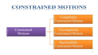
3. Constrained Motions
1. Completely constrained motion
When the motion between a pair is limited to a definite direction irrespective
of the direction of force applied, then the motion is said to be a completely
constrained motion.
Example:
The motion of a square bar in a square hole
The motion of a shaft with collars at each end in a circular hole
4. 2. Incompletely constrained motion
When the motion between a pair can take place in more than one direction,
then it can be an incompletely constrained motion.
E.g.:A circular bar or shaft in a circular hole
It may either rotate or slide in a hole. These both motions have no relationship
with the other (automobile wheel).
5. 3. Successfully constrained motion
When the motion between the elements, forming a pair, is such that the
constrained motion is not completed by itself, but by some other means
E.g.: Shaft in a foot-step bearing, I C engine valve, Piston inside an cylinder.
6. Kutzbach Criterion
Kutzbach equation to calculate the movability of a mechanism having plane motion is
n = 3(l-1) - 2j – h
If there are no two degree freedom pairs (i.e higher pairs), then h = 0.
n = 3(l-1) – 2j - h
7. Kutzbach Criterion
For binary joint n = 0
For four bar mechanism n = 1
For five bar mechanism n = 2
For five bar mechanism n = 0
For six bar mechanism n = -1 (redundant constraints forming statically indeterminate structure)
8. Kutzbach Criterion
For higher pair or two degree of freedom joints is shown as below.
n = 3 (3-1) – 2 * 2 – 1 = 1
n = 3 (4-1) – 2 * 3 – 1 = 2
Grubler’s Condition:
9. • Grubler’s mechanism is obtained by substituting n = 1 and h = 0
in Kutzbach criterion as below.
9
We know that, n = 3 (l-1) – 2j - h
l= 3 (l -1) – 2j
or
3l – 2j – 4 = 0
This equation is known as Grubler’s criterion for plane
mechanism
Grubler’s criterion for plane mechanism
10. We know that Kutzbach criterion for spatial mechanism is
10
n = 6(l-1) – 5P1 – 4P2 – 3P3 – 2P4 – 1P5
substitute n = 1; P2, P3 , … P5 = 0
1 = 6(l-1) – 5P1 (or) 6l – 5P1 – 7 = 0
This equation is known as Grubler’s equation for spatial mechanism.
Grubler’s equation for spatial mechanism
13. Inversion of Mechanisms
Mechanism:
When one of the links of kinematic chains is fixed, the chain is known as mechanisms.
We can obtain a number of mechanisms by changing the fixed link.
Mechanism Inversion:
Method of obtaining different mechanism by fixing different links in a kinematic chain is known as
inversion of mechanisms.
Driver:
The part of mechanism which initially moves with respect to frame or fixed link is known as driver.
Follower:
The part of mechanism to which the motion is transmitted is called as follower.
Note: Most of mechanisms are reversible. For example, in a reciprocating engine the piston is driver and
flywheel is follower while in a reciprocating air compressor, the flywheel is a driver.
14. Inversion of Mechanism
• A mechanism is one in which one of the links of a kinematic chain is fixed.
• Different mechanisms can be obtained by fixing different links of the same
kinematic chain.
15. Kinematic Chain
When the kinematic pairs are coupled in such a way that the last link is joined to the
first link to transmit definite motion (i.e. completely or successfully constrained
motion).
16. Types of Kinematic Chains
1. Four bar chain or quadric cyclic chain
2. Single slider crank chain
3. Double slider crank chain
17. 1. Four bar chain or quadric chain
• Four bar chain (mechanism) is the simplest and the
basic kinematic chain and consists of four rigid links
• Each of them forms a turning pair at A, B, C and D.
The link that makes a complete revolution is called a crank
• The four links may be of different lengths.
• According to Grashof ’s law for a four bar mechanism, “the sum of the
shortest and longest link lengths should not be greater than the sum of the
remaining two link lengths” if there is to be continuous relative motion between
the two links.
18. 9/6/2022
Grashof’s Criteria
Used to determine whether or not at least one of the links can rotate 360o
the sum of the shortest and longest links of a planar four-bar mechanism cannot be greater than the sum of
the remaining two links if there is to be continuous relative rotation between the two links.
s + l < p + q
s
q
l
p
20. 9/6/2022
Grashof Mechanisms (s+l < p+q)
s
l
q
p
q
l
s
p
Crank-Rocker Rocker-Crank
Shortest link pinned to ground and rotates 360o
21. 9/6/2022
Grashof Mechanisms (s+l < p+q)
p
q
l
s
p
s
q
l
Drag-Link
- Both input and output links rotate 360o
Double-Rocker
- Coupler rotates 360o
22. 1. Four bar chain or quadric chain
• The shortest link, will make a complete revolution relative to the other three
In Fig., AD (link 4 ) is a crank.
links crank or driver.
• link BC (link 2) which makes a partial rotation or oscillates is known as lever or rocker or follower
• link CD (link 3) which connects the crank and lever is called connecting rod or coupler.
• The fixed link AB (link 1) is known as frame of the mechanism.
The mechanism transforms rotary motion into oscillating motion.
23.
24. • In this mechanism, the links AD and BC (having equal length) act as cranks and are connected to
the respective wheels.
• The link CD acts as a coupling rod.
• The link AB is fixed in order to maintain a constant centre to centre distance between them.
Purpose: Transmitting rotary motion from one wheel to the other wheel.
25.
26. Purpose of this mechanism is to convert rotary motion into reciprocating motion.
When the crankAB rotates about the fixed point A.
The lever oscillates about another fixed point D.
The end E of lever is connected to a piston rod which reciprocates in a cylinder.`
27. The four links are : fixed link at A, link AC, link CE and link BFD. Links CE and BFD act as levers.
On displacement of the mechanism, the tracing point E at
the end of the link CE traces out approximately a straight
line.
31. Pendulum Pump or Bull Engine
When the crank (link 2) is given a rotary motion, the connecting rod (link 3) oscillates
about a pin pivoted to the fixed link 4 at A. The piston attached to the piston rod (link
1) reciprocates.
32. Link 3 forming the turning pair is fixed and it corresponds to the connecting rod of a
reciprocating steam engine mechanism.
When the crank (link 2) rotates, the piston attached to piston rod (link 1)
reciprocates and the cylinder (link 4) oscillates about a pin pivoted to the fixed link
at A
A
33.
34. It consists of seven cylinders in one plane all revolve about fixed centre D.
Cylinders form link 1, Crank (link 2) is fixed. When the connecting rod (link4) rotates,
the piston (link 3) reciprocates inside the cylinder.
36. A mechanism used in shaping and slotting
machines, where the metal is cut intermittently.
• Link AC (i.e. link 3) is fixed.
• Crank CB revolves with uniform angular speed
about the fixed center C.
• Sliding block attached to the crank pin at B slides
along the slotted bar AP, thus causing AP to
oscillate about the pivoted pointA.
• Short link PR transmits the motion from AP to the
ram which carries the tool and reciprocates along
the line of stroke R1R2
37. • The forward or cutting stroke occurs when the
crank rotates from the position CB1 to CB2 (or
through an angle β
)in the clockwise direction.
• The return stroke occurs when the crank rotates
from the position CB2 to CB1 (or through angle
α) in the clockwise direction.
40. • This inversion is obtained by fixing the slotted plate (link 4).
• fixed plate or link 4 has two straight grooves cut in it, at right angles to each other.
• link 1 and link 3, are known as sliders and form sliding pairs with link 4.
• link AB (link 2) is a bar which forms turning pair with links 1 and 3.
• When the links 1 and 3 slide along their respective grooves, any point on the link 2 such as P traces
out an ellipse on the surface of link 4
41. Show that AP and BP are the semi-major axis and semi-minor axis of the ellipse.
OX and OY as horizontal and vertical axes
let the link BA is inclined at an angle θwith the horizontal,
Now the co-ordinates of the point P on the link BA will be
This is the equation of an ellipse
42. • This mechanism is used for converting rotary motion into a reciprocating motion.
• The inversion is obtained by fixing either the link 1 or link 3. link 1 is fixed.
• In this mechanism, when the link 2 (crank) rotates about B as centre, the link 4
(frame) reciprocates.
• The fixed link 1 guides the frame.