High Profile Call Girls Nagpur Meera Call 7001035870 Meet With Nagpur Escorts
Cia i kom - answer key
1. Course Code & Title : ME8492 & KINEMATICS OF MACHINERY
II Year Mechanical CIA I – ANSWER KEY AY: 2019-2020 SEM: EVEN
1. State Grubler’s criteria for a mechanism.
The Grubler’s criterion applies to mechanisms with only single degree of freedom joints where
the overall movability of the mechanism is unity. Substituting n = 1 and h = 0 in Kutzbach equation, we
have
1 = 3 (l – 1) – 2 j or 3l – 2j – 4 = 0
2. Explain transmission angle of four bar mechanism and what the worst value of transmission angle
is.
In a four bar chain mechanism, the angle between the coupler and the follower (driven) link is
called as the transmission angle. Worst value is less than 450.
3. Distinguish between machine and mechanism.
Mechanism with four links is known as simple mechanism, and the mechanism with
more than four links is known as compound mechanism. When a mechanism is required to transmit
power or to do some particular type of work, it then becomes a machine. In such cases, the various links
or elements have to be designed to withstand the forces (both static and kinetic) safely.
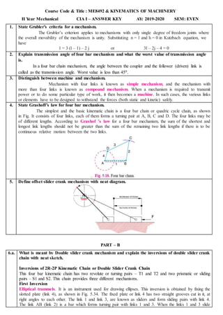
4. State Grashoff’s law for four bar mechanism.
The simplest and the basic kinematic chain is a four bar chain or quadric cycle chain, as shown
in Fig. It consists of four links, each of them forms a turning pair at A, B, C and D. The four links may be
of different lengths. According to Grashof ’s law for a four bar mechanism, the sum of the shortest and
longest link lengths should not be greater than the sum of the remaining two link lengths if there is to be
continuous relative motion between the two links.
5. Define offset slider crank mechanism with neat diagram.
PART – B
6.a. What is meant by Double slider crank mechanism and explain the inversions of double slider crank
chain with neat sketch.
Inversions of 2R-2P Kinematic Chain or Double Slider Crank Chain
This four bar kinematic chain has two revolute or turning pairs – T1 and T2 and two prismatic or sliding
pairs – S1 and S2. This chain provides three different mechanisms.
First Inversion
Elliptical trammels. It is an instrument used for drawing ellipses. This inversion is obtained by fixing the
slotted plate (link 4), as shown in Fig. 5.34. The fixed plate or link 4 has two straight grooves cut in it, at
right angles to each other. The link 1 and link 3, are known as sliders and form sliding pairs with link 4.
The link AB (link 2) is a bar which forms turning pair with links 1 and 3. When the links 1 and 3 slide
2. along their respective grooves, any point on the link 2 such as P traces out an ellipse on the surface of link
4, as shown in Fig. 5.34 (a). A little consideration will show that AP and BP are the semi-major axis and
semi-minor axis of the ellipse respectively. This can be proved as follows :
Second Inversion
An oldham's coupling is used for connecting two parallel shafts whose axes are at a small distance apart.
The shafts are coupled in such a way that if one shaft rotates, the other shaft also rotates at the same
speed. This inversion is obtained by fixing the link 2, as shown in Fig. 5.36 (a). The shafts to be
connected have two flanges (link 1 and link 3) rigidly fastened at their ends by forging.
Third Inversion Scotch yoke mechanism
This mechanism is used for converting rotary motion into a reciprocating motion. The inversion is
obtained by fixing either the link 1 or link 3. In Fig. 5.35, link 1 is fixed. In this mechanism, when the
link 2 (which corresponds to crank) rotates about B as centre, the link 4 (which corresponds to a frame)
reciprocates. The fixed link 1 guides the frame.
6.b. (i) Briefly explain the various types of constrained motions. (6)
1. Completely constrained motion. When the motion between a pair is limited to a definite
direction irrespective of the direction of force applied, then the motion is said to be a completely
constrained motion. For example, the piston and cylinder (in a steam engine) form a pair and the motion
of the piston is limited to a definite direction (i.e. it will only reciprocate) relative to the cylinder
irrespective of the direction of motion of the crank.
3. 2. Incompletely constrained motion. When the motion between a pair can take place in more than one
direction, then the motion is called an incompletely constrained motion. The change in the direction of
impressed force may alter the direction of relative motion between the pair. A circular bar or shaft in a
circular hole, as shown in Fig. 5.4, is an example of an incompletely constrained motion as it may either
rotate or slide in a hole. These both motions have no relationship with the other.
3. Successfully constrained motion. When the motion between the elements, forming a pair,is such that
the constrained motion is not completed by itself, but by some other means, then the motion is said to be
successfully constrained motion. Consider a shaft in a foot-step bearing as shown in Fig. 5.5. The shaft
may rotate in a bearing or it may move upwards. This is a case of incompletely constrained motion. But if
the load is placed on the shaft to prevent axial upward movement of the shaft, then the motion of the pair
is said to be successfully constrained motion.
(ii) What is meant by kinematic pair and Explain it with neat sketch based on nature of relative
motion and nature of contact between the links? (6)
1. According to the type of relative motion between the elements. The kinematic pairs according to
type of relative motion between the elements may be classified as discussed below:
(a) Sliding pair. When the two elements of a pair are connected in such a way that one can only slide
relative to the other, the pair is known as a sliding pair. The piston and cylinder, cross-head and guides of
a reciprocating steam engine, ram and its guides in shaper, tail stock on the lathe bed etc. are the
examples of a sliding pair. A little consideration will show, that a sliding pair has a completely
constrained motion.
(b) Turning pair. When the two elements of a pair are connected in such a way that one can only turn or
revolve about a fixed axis of another link, the pair is known as turning pair. A shaft with collars at both
ends fitted into a circular hole, the crankshaft in a journal bearing in an engine, lathe spindle supported in
head stock, cycle wheels turning over their axles etc. are the examples of a turning pair. A turning pair
also has a completely constrained motion.
(c) Rolling pair. When the two elements of a pair are connected in such a way that one rolls over another
fixed link, the pair is known as rolling pair. Ball and roller bearings are examples of rolling pair.
(d) Screw pair. When the two elements of a pair are connected in such a way that one element can turn
about the other by screw threads, the pair is known as screw pair. The lead screw of a lathe with nut, and
bolt with a nut are examples of a screw pair.
(e) Spherical pair. When the two elements of a pair are connected in such a way that one element (with
spherical shape) turns or swivels about the other fixed element, the pair formed is called a spherical pair.
The ball and socket joint, attachment of a car mirror, pen stand etc., are the examples of a spherical pair.
7.a. What is kinematic inversion? Discuss any three applications of inversions of single slider crank
4. mechanisms with suitable examples.
Single Slider Crank Chain
A single slider crank chain is a modification of the basic four bar chain. It consists of one sliding pair and
three turning pairs. It is, usually, found in reciprocating steam engine mechanism. This type of
mechanism converts rotary motion into reciprocating motion and vice versa. In a single slider crank
chain, as shown in Fig, the links 1 and 2, links 2 and 3, and links 3 and 4 form three turning pairs while
the links 4 and 1 form a sliding pair.
Inversions of Single Slider Crank Chain
1. Pendulum pump or Bull engine. In this mechanism, the inversion is obtained by fixing the cylinder
or link 4 (i.e. sliding pair), as shown in Fig. In this case, when the crank (link 2) rotates, the connecting
rod (link 3) oscillates about a pin pivoted to the fixed link 4 at A and the piston attached to the piston rod
(link 1) reciprocates. The duplex pump which is used to supply feed water to boilers have two pistons
attached to link 1.
2. Oscillating cylinder engine. The arrangement of oscillating cylinder engine mechanism, as shown in
Fig, is used to convert reciprocating motion into rotary motion. In this mechanism, the link 3 forming the
turning pair is fixed. The link 3 corresponds to the connecting rod of a reciprocating steam engine
mechanism. When the crank (link 2) rotates, the piston attached to piston rod (link 1) reciprocates and the
cylinder (link 4) oscillates about a pin pivoted to the fixed link at A.
3. Rotary internal combustion engine or Gnome engine. Sometimes back, rotary internal combustion
engines were used in aviation. But now-a-days gas turbines are used in its place. It consists of seven
cylinders in one plane and all revolves about fixed centre D, as shown in Fig. while the crank (link 2) is
fixed. In this mechanism, when the connecting rod (link 4) rotates, the piston (link 3) reciprocates inside
the cylinders forming link 1.
5. 4. Crank and slotted lever quick return motion mechanism. This mechanism is mostly used in
shaping machines, slotting machines and in rotary internal combustion engines. In this mechanism, the
link AC (i.e. link 3) forming the turning pair is fixed, as shown in Fig. The link 3 corresponds to the
connecting rod of a reciprocating steam engine. The driving crank
CB revolves with uniform angular speed about the fixed centre C.
5. Whitworth quick return motion mechanism. This mechanism is mostly used in shaping and slotting
machines. In this mechanism, the link CD (link 2) forming the turning pair is fixed, as shown in Fig. The
link 2 corresponds to a crank in a reciprocating steam engine. The driving crank CA (link 3) rotates at a
uniform angular speed. The slider (link 4) attached to the crank pin at A slides along the slotted bar PA
(link 1) which oscillates at a pivoted point D. The connecting rod PR carries the ram at R to which a
cutting tool is fixed. The motion of the tool is constrained along the line RD produced, i.e. along a line
passing through D and perpendicular to CD.
7.b. (i) Find the degree of freedom for the mechanisms shown in Fig. (9)
Solutons:
6. (i) Degree of Freedom – 1
(ii) Degree of Freedom – 2
(iii) Degree of Freedom – 3
(ii) Explain mechanical advantage related to the Four bar chain mechanism. (3)
The Mechanical advantage is defined as the ratio of the output torque to the input torque. It is also
defined as the ratio of the load to the effort.
PART – C (1 X 14 = 14 Marks)
8.a. What do you understand by inversion of a kinematic chain? Describe the mechanisms obtained by
inversion of the Four Bar Chain.
Kinematic chain is a combination of four or more kinematic pairs, such that the relative
motion between the links or elements is completely constrained. The simplest and the basic kinematic chain
is a four bar chain or quadric cycle chain, as shown in Fig. It consists of four links, each of them forms a
turning pair at A, B, C and D. The four links may be of different lengths. According to Grashoff’s law for a
four bar mechanism, the sum of the shortest and longest link lengths should not be greater than the sum of
the remaining two link lengths if there is to be continuous relative motion between the two links.
Inversions of Four Bar Chain
Though there are many inversions of the four bar chain, yet the following are important from the subject
Point of view
1. Beam engine (crank and lever mechanism).A part of the mechanism of a beam engine (also
known as crank and lever mechanism) which consists of four links is shown in Fig. In this
mechanism, when the crank rotates about the fixed centre A lever oscillates about a fixed centre D.
The end E of the lever CDE is connected to a piston rod which reciprocates due to the rotation of the
crank. In other words, the purpose of this mechanism is to convert rotary motion into reciprocating
motion.
2. Coupling rod of a locomotive (Double crank mechanism). The mechanism of a coupling rod of
a locomotive (also known as double crank mechanism) which consists of four links is shown in Fig.
In this mechanism, the links AD and BC (having equal length) act as cranks and are connected to the
respective wheels. The link CD acts as a coupling rod and the link AB is fixed in order to maintain a
constant centre to centre distance between them. This mechanism is meant for transmitting rotary
motion from one wheel to the other wheel.
7. 3. Watt’s indicator mechanism (Double lever mechanism). A *Watt’s indicator mechanism (also
known as Watt's straight line mechanism or double lever mechanism) which consists of four links, is
shown in Fig. The four links are: fixed link at A, link AC, link CE and link BFD. It may be noted
that BF and FD form one link because these two parts have no relative motion between them. The
links CE and BFD act as levers. The displacement of the link BFD is directly proportional to the
pressure of gas or steam which acts on the indicator plunger. On any small displacement of the
mechanism, the tracing point E at the end of the link CE traces out approximately a straight line.
8.b. (i) With a suitable diagram, explain how a pantograph works. What are its uses? (7)
PANTOGRAPH:
1. It is a four bar linkage used to produce paths exactly similar to the ones traced out by a point on the
linkage.
2. The paths so produced are usually on an enlarged or reduced scale and may be straight or curved ones.
1. It consists of a jointed parallelogram ABCD as shown in the figure.
2. It is made up of bars connected by turning pairs.
3. From similar triangles OAD and OBE, Let O be fixed and the points D and E move to some new
positions D‟ and E‟.
(ii) Sketch Hooke's joint and derive the condition for equal speeds of driving and driven shafts.
A Hooke's joint or Universal joint is a joint which connects two non parallel shafts inclined
at a small angle to help transmit motion between them.