Download as PDF, PPTX


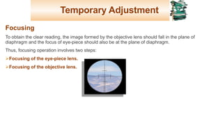
![Temporary Adjustment
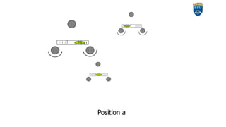
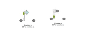
Step 3: The bubble of the other level tube is then brought to the centre of the level
tube by rotating the third foot screw either inward or outward. [In step 1 itself, the
other plate level will be parallel to the line joining the third foot screw and the centre
of the line joining the previous two foot screws.]
Step 4: Repeat Step 2 and step 3
in the same quadrant till both the
bubble remain central.
22](https://image.slidesharecdn.com/planeandappliedsurveying-2theodolitetheoreticalpart-1-220910195056-3c30e919/85/Introduction-About-Theodolite-Instrument-Theoretical-part-22-320.jpg)


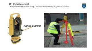
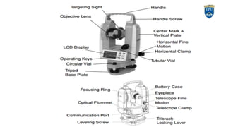
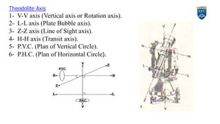
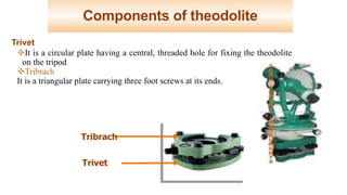
The document provides a comprehensive overview of theodolites, a surveying instrument used for measuring horizontal and vertical angles. It details the components, setup, temporary and permanent adjustments required for accurate measurements, as well as common sources of errors encountered during observations. Various uses of the theodolite, such as measuring angles and elevation differences, are also highlighted.


