Downloaded 637 times
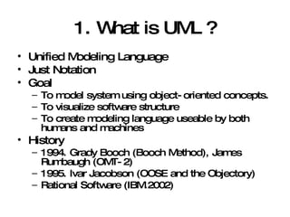
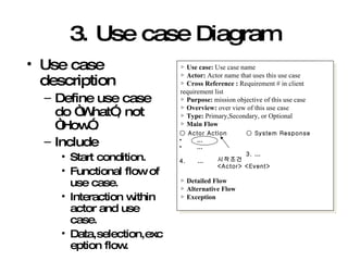
![4. Activity / State Diagram Working Check System Clock Input user action Display user action to screen action Wait for user action Refresh time [Time check] Run screen saver H [Time over] Press key or move mouse History State Sub state Sub state State transition](https://image.slidesharecdn.com/introducingumlanddevelopmentprocess-123923935821-phpapp01/85/Introducing-Uml-And-Development-Process-14-320.jpg)

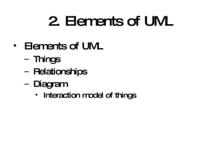
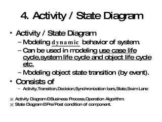
![7. Collaboration Diagram :GUI[Process] :OS :CPU :Video Card :Monitor Key stroke 1: notify(Key stroke) 4: notify(Key) 3: update(key stroke) 5: display(Key) 6: feedback() :GUI[Init] <<become>> State State transition User](https://image.slidesharecdn.com/introducingumlanddevelopmentprocess-123923935821-phpapp01/85/Introducing-Uml-And-Development-Process-21-320.jpg)
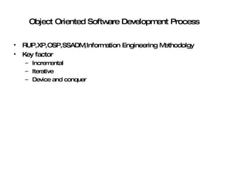
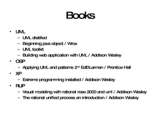

The document introduces Unified Modeling Language (UML) by describing its history, elements, and common diagram types. It explains that UML was created to model systems using object-oriented concepts and visualize software structure. The key elements are things, relationships, and diagrams. Common diagram types include use case diagrams, class diagrams, sequence diagrams, and deployment diagrams.