Download as PDF, PPTX
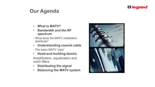
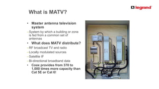

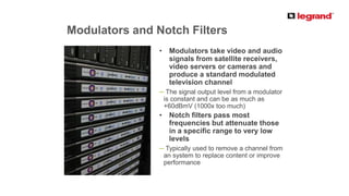
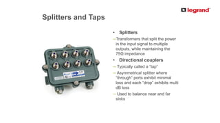
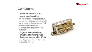
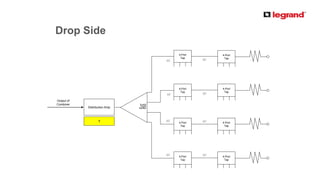
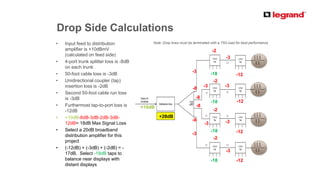

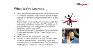


This document provides an introduction and overview of master antenna television (MATV) systems. It discusses what an MATV system is, the RF spectrum used, and the types of signals distributed over coaxial cable. The document outlines the key components of an MATV system, including amplification, equalization, notch filters, splitters, taps, and combiners. It also discusses designing an MATV system, including calculating system gain to ensure a constant power level across all bands as signals are distributed from the head-end to multiple zones and displays. The document emphasizes that quality MATV installation depends on quality coaxial cable and accurately accounting for all insertion losses across the distribution network.


![Presentation1[1]abiout nhnfdfkmdjbf.pptx](https://cdn.slidesharecdn.com/ss_thumbnails/presentation11-240718051625-2893c777-thumbnail.jpg?width=640&height=640&fit=bounds)


