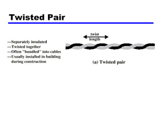
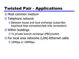
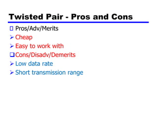
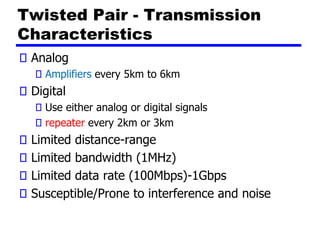
Notes #4
Transmission Media
Overview
Transmission media is divided into two categories:
➢ Guided – wired, also known as bounded media
➢ Unguided – wireless, also referred to as unbounded
media
Characteristics and quality of transmission is determined
by medium and signal
For guided, the medium is more important
For unguided, the bandwidth produced by the antenna
is more important
In wireless transmission, we make use of some form of
antenna
Key concerns are data rate and distance
Transmission medium Design
Factors
Bandwidth
Higher bandwidth gives higher data rate
Transmission impairments
Attenuation, noise, etc
Attenuation is the decay/falling off/degradation of a
signal as the distance increases.
Interference especially electromagnetic
interference.
Number of receivers
In guided media
More receivers (multi-point) introduce more
attenuation
Electromagnetic Spectrum
Guided Transmission Media
Twisted Pair cable
Coaxial cable
Optical fiber
Twisted Pair
Twisted Pair - Applications
Most common medium
Telephone network
Between house and local exchange (subscriber
loop/local loop connection/last mile connection)
Within buildings
To private branch exchange (PBX)/switch
For local area networks (LAN)-Ethernet cable
10Mbps or 100Mbps
Twisted Pair - Pros and Cons
Pros/Adv/Merits
➢ Cheap
➢ Easy to work with
❑Cons/Disadv/Demerits
➢ Low data rate
➢ Short transmission range
Twisted Pair - Transmission
Characteristics
Analog
Amplifiers every 5km to 6km
Digital
Use either analog or digital signals
repeater every 2km or 3km
Limited distance-range
Limited bandwidth (1MHz)
Limited data rate (100Mbps)-1Gbps
Susceptible/Prone to interference and noise
Unshielded and Shielded TP
Unshielded Twisted Pair (UTP)
Ordinary telephone wire
Cheapest-It does not have an outer cover/shield
Easiest to install
Suffers from external EM interference
Shielded Twisted Pair (STP)
Metal braid or sheathing (outer covering) that
reduces interference
More expensive-Extra material for the cover
Harder to handle (thick, heavy)
UTP Categories
Cat 3
up to 16MHz
Voice grade found in most offices
Twist length of 7.5 cm to 10 cm
Cat 4
up to 20 MHz
Cat 5
up to 100MHz
Commonly pre-installed in new office buildings
Twist length 0.6 cm to 0.85 cm
Near End Crosstalk-
Interference
Coupling of signal from one pair to another
Coupling takes place when transmit signal
entering the link couples back to receiving pair
i.e. near transmitted signal is picked up by near
receiving pair
Coaxial Cable
Coaxial Cable Applications
Most versatile medium
Television distribution
Ariel to TV
Cable TV
Long distance telephone transmission
Can carry 10,000 voice calls simultaneously
Being replaced by fiber optic
Short distance computer systems links
Local area networks
Coaxial Cable - Transmission
Characteristics
Analog
Amplifiers every few km
Closer if higher frequency
Up to 500MHz
Digital
Repeater every 1km
Closer for higher data rates
Optical Fiber
Optical Fiber - Benefits
Greater capacity
Data rates of hundreds of Gbps
Smaller size & weight-Easy to handle
Lower attenuation
Electromagnetic isolation-No interference
Greater repeater spacing-Less repeater is used.
10s of km at least
Optical Fiber - Applications
Long-haul trunks/Long distance backbone
transmission (High capacity transmission) E.g
SEACOM and TEAMS cable interconnecting the
different continents.
Metropolitan trunks-within cities E.g “Faiba”
from Jamii Telecoms in Kenya
Rural exchange trunks-Local switch
interconnections
Subscriber loops-To the Home/customer
LANs: But is will be expensive.
Optical Fiber - Transmission
Characteristics
Act as wave guide for 1014 to 1015 Hz
Portions of infrared and visible spectrum
Two Optical (fiber) signal sources:
➢ Light Emitting Diode (LED)
Cheaper
Wider operating temp range
Last longer
➢ Injection Laser Diode (ILD)
More expensive
More efficient
Greater data rate
Wavelength Division Multiplexing (WDM)-Dense WDM
Optical Fiber Transmission Modes
(Modes=Number of simultaneous
signals transmitted)
Wireless Transmission
Unguided media-No physical cable or wire
Transmission and reception via antenna
Directional antenna
Focused beam
Careful alignment required-Line of sight (LOS)
Omnidirectional
Signal spreads in all directions
Can be received by many antennae
Frequencies
2GHz to 40GHz
Microwave transmission
Highly directional-LOS requirement
Point to point
Satellite
30MHz to 1GHz
Omnidirectional
Broadcast radio
3 x 10¹¹ to 2 x 10¹⁴
Infrared-Short links
Local
Terrestrial Microwave
Transmission (1)
Parabolic dish
Focused beam
Line of sight
Long haul telecommunications
Higher frequencies give higher data rates
Terrestrial
Microwave Transmission(2)
uses the radio frequency spectrum, commonly
from 2 to 40 Ghz
transmitter is a parabolic dish, mounted as high
as possible
used by common carriers as well as by private
networks
requires unobstructed line of sight between
source and receiver
curvature of the earth requires stations (called
repeaters) to be ~30 miles apart
Satellite Microwave
Satellite is relay station-Mounted on the Orbit
Satellite receives on one frequency, amplifies or
repeats signal and transmits on another
frequency-Different uplink and down link
frequencies
Requires geo-stationary orbit
Height of 35,784km (22,300 miles)
Television-DSTV
Long distance telephone-Satellite-Suraya
Private business networks-E.g Remote Site
connections for mobile telephone service
dish
dish
uplink station downlink station
satellite
transponder
22,300 miles
Satellite Transmission Process
Principal Satellite Transmission
Bands
C band: 4(downlink) - 6(uplink) GHz
the first to be designated
Ku band: 12(downlink) -14(uplink) GHz
rain interference is the major problem
Ka band: 19(downlink) - 29(uplink) GHz
equipment needed to use the band is still very
expensive
Broadcast Radio
Omnidirectional-
FM radio
UHF and VHF television
Line of sight-Clear of obstacles and avoid signal
reflections on different surfaces e.g. walls
Suffers from multipath interference
Reflections
Infrared
Modulate noncoherent infrared light
Line of sight (or reflections will occur)
Blocked by walls
e.g. TV remote control, IRD port
Required Reading
Stallings Chapter 4

APT2050 Notes#4 - Transmission Media(1).pdf

  • 1.
  • 2.
    Overview Transmission media isdivided into two categories: ➢ Guided – wired, also known as bounded media ➢ Unguided – wireless, also referred to as unbounded media Characteristics and quality of transmission is determined by medium and signal For guided, the medium is more important For unguided, the bandwidth produced by the antenna is more important In wireless transmission, we make use of some form of antenna Key concerns are data rate and distance
  • 3.
    Transmission medium Design Factors Bandwidth Higherbandwidth gives higher data rate Transmission impairments Attenuation, noise, etc Attenuation is the decay/falling off/degradation of a signal as the distance increases. Interference especially electromagnetic interference. Number of receivers In guided media More receivers (multi-point) introduce more attenuation
  • 4.
  • 5.
    Guided Transmission Media TwistedPair cable Coaxial cable Optical fiber
  • 6.
  • 7.
    Twisted Pair -Applications Most common medium Telephone network Between house and local exchange (subscriber loop/local loop connection/last mile connection) Within buildings To private branch exchange (PBX)/switch For local area networks (LAN)-Ethernet cable 10Mbps or 100Mbps
  • 8.
    Twisted Pair -Pros and Cons Pros/Adv/Merits ➢ Cheap ➢ Easy to work with ❑Cons/Disadv/Demerits ➢ Low data rate ➢ Short transmission range
  • 9.
    Twisted Pair -Transmission Characteristics Analog Amplifiers every 5km to 6km Digital Use either analog or digital signals repeater every 2km or 3km Limited distance-range Limited bandwidth (1MHz) Limited data rate (100Mbps)-1Gbps Susceptible/Prone to interference and noise
  • 10.
    Unshielded and ShieldedTP Unshielded Twisted Pair (UTP) Ordinary telephone wire Cheapest-It does not have an outer cover/shield Easiest to install Suffers from external EM interference Shielded Twisted Pair (STP) Metal braid or sheathing (outer covering) that reduces interference More expensive-Extra material for the cover Harder to handle (thick, heavy)
  • 11.
    UTP Categories Cat 3 upto 16MHz Voice grade found in most offices Twist length of 7.5 cm to 10 cm Cat 4 up to 20 MHz Cat 5 up to 100MHz Commonly pre-installed in new office buildings Twist length 0.6 cm to 0.85 cm
  • 12.
    Near End Crosstalk- Interference Couplingof signal from one pair to another Coupling takes place when transmit signal entering the link couples back to receiving pair i.e. near transmitted signal is picked up by near receiving pair
  • 13.
  • 14.
    Coaxial Cable Applications Mostversatile medium Television distribution Ariel to TV Cable TV Long distance telephone transmission Can carry 10,000 voice calls simultaneously Being replaced by fiber optic Short distance computer systems links Local area networks
  • 15.
    Coaxial Cable -Transmission Characteristics Analog Amplifiers every few km Closer if higher frequency Up to 500MHz Digital Repeater every 1km Closer for higher data rates
  • 16.
  • 17.
    Optical Fiber -Benefits Greater capacity Data rates of hundreds of Gbps Smaller size & weight-Easy to handle Lower attenuation Electromagnetic isolation-No interference Greater repeater spacing-Less repeater is used. 10s of km at least
  • 18.
    Optical Fiber -Applications Long-haul trunks/Long distance backbone transmission (High capacity transmission) E.g SEACOM and TEAMS cable interconnecting the different continents. Metropolitan trunks-within cities E.g “Faiba” from Jamii Telecoms in Kenya Rural exchange trunks-Local switch interconnections Subscriber loops-To the Home/customer LANs: But is will be expensive.
  • 19.
    Optical Fiber -Transmission Characteristics Act as wave guide for 1014 to 1015 Hz Portions of infrared and visible spectrum Two Optical (fiber) signal sources: ➢ Light Emitting Diode (LED) Cheaper Wider operating temp range Last longer ➢ Injection Laser Diode (ILD) More expensive More efficient Greater data rate Wavelength Division Multiplexing (WDM)-Dense WDM
  • 20.
    Optical Fiber TransmissionModes (Modes=Number of simultaneous signals transmitted)
  • 21.
    Wireless Transmission Unguided media-Nophysical cable or wire Transmission and reception via antenna Directional antenna Focused beam Careful alignment required-Line of sight (LOS) Omnidirectional Signal spreads in all directions Can be received by many antennae
  • 22.
    Frequencies 2GHz to 40GHz Microwavetransmission Highly directional-LOS requirement Point to point Satellite 30MHz to 1GHz Omnidirectional Broadcast radio 3 x 10¹¹ to 2 x 10¹⁴ Infrared-Short links Local
  • 23.
    Terrestrial Microwave Transmission (1) Parabolicdish Focused beam Line of sight Long haul telecommunications Higher frequencies give higher data rates
  • 24.
    Terrestrial Microwave Transmission(2) uses theradio frequency spectrum, commonly from 2 to 40 Ghz transmitter is a parabolic dish, mounted as high as possible used by common carriers as well as by private networks requires unobstructed line of sight between source and receiver curvature of the earth requires stations (called repeaters) to be ~30 miles apart
  • 25.
    Satellite Microwave Satellite isrelay station-Mounted on the Orbit Satellite receives on one frequency, amplifies or repeats signal and transmits on another frequency-Different uplink and down link frequencies Requires geo-stationary orbit Height of 35,784km (22,300 miles) Television-DSTV Long distance telephone-Satellite-Suraya Private business networks-E.g Remote Site connections for mobile telephone service
  • 26.
    dish dish uplink station downlinkstation satellite transponder 22,300 miles Satellite Transmission Process
  • 27.
    Principal Satellite Transmission Bands Cband: 4(downlink) - 6(uplink) GHz the first to be designated Ku band: 12(downlink) -14(uplink) GHz rain interference is the major problem Ka band: 19(downlink) - 29(uplink) GHz equipment needed to use the band is still very expensive
  • 28.
    Broadcast Radio Omnidirectional- FM radio UHFand VHF television Line of sight-Clear of obstacles and avoid signal reflections on different surfaces e.g. walls Suffers from multipath interference Reflections
  • 29.
    Infrared Modulate noncoherent infraredlight Line of sight (or reflections will occur) Blocked by walls e.g. TV remote control, IRD port
  • 30.