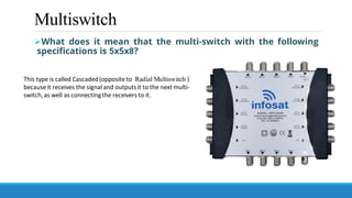
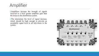
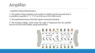
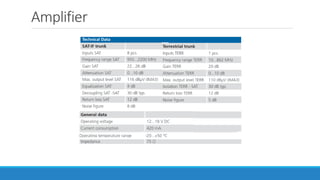
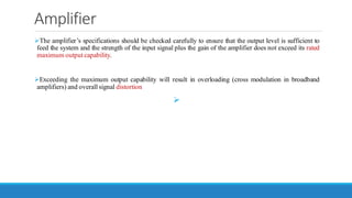
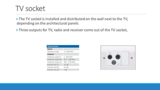
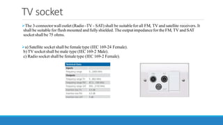
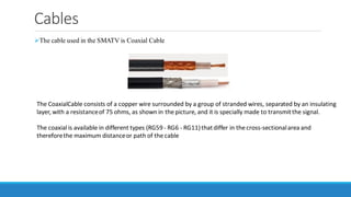
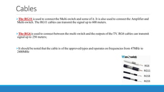
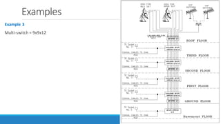
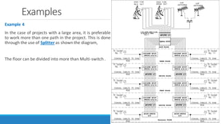
Planning and Implementing Communications Systems in
Residential and Non-Residential Buildings
Dr. Abdelhay Ali
Lecture 2
2
References
Textbooks
1- Low Current Systems for Electrical Power Engineers by prof. Mahmoud Gilany
2- Light Current Systems Guide by Dr. Abd Almonem Shaban
3- Low-Current Systems Engineer'S Technical Handbook , A Guide to Design and
Supervision" by Habbieb Mansour.
Online classes at other schools
Light Current Course 2021 Level#3
3
Outline
1. Multi-switch
2. Amplifier
3. Splitter
4. TV socket
5. Cables
6. Examples
4
Outline
1. Multi-switch
2. Amplifier
3. Splitter
4. TV socket
5. Cables
6. Examples
5
Multiswitch
➢Technical Specifications of Multi-switch
1- The number of entry and exitports. Inputs/Outputs
Inputs are based on the number of satellites and the terrestrial arial; Knowing that each satellite has four
points (Vertical H / L and Horizontal H / L), and the terrestrial only one point. In the SMATV, the lowest number
of inputs equals 5 outlets
➢In the case of using 2 satellites and a terrestrial arial, we will need 9
inputs; Therefore, the multi-switch is available in standard numbers
according to the companies. Produced where it is available in different
capacitiesfrom17-13-9 -5 Inputs
➢As for the outputs, it depends on the number of users (ie the number
of receivers);
Multiswitch
Multiswitch
➢Technical Specifications of Multi-switch
2- Through Loss
It means the value of the loss in the signal coming out of the multi-switch and transmitted to the next multi-
switch,and it is measuredin decibels.
Multiswitch
➢Technical Specifications of Multi-switch
3-FrequencyRange
It means the range of frequencies that the Multi-switch receives from the LNB and the antenna; As we
mentioned earlier, the electrical signal IF frequency ranges from 950 MHz to 2150 MHz, which is related to the
LNB output, and the RF frequencyrangesfrom 47 MHz to 862MHz.
Multiswitch
➢Technical Specifications of Multi-switch
Multiswitch
➢What does it mean that the multi-switch with the following
specifications is 5x5x8?
This type is called Cascaded(opposite to Radial Multiswitch )
because it receives the signal and outputsit to the next multi-
switch,as well as connectingthe receivers to it.
Multiswitch
➢Cascaded multi-switch
Multiswitch
➢Radial Multiswitch
Outline
1. Multi-switch
2. Amplifier
3. Splitter
4. TV socket
5. Cables
6. Examples
14
Amplifier
➢The amplifier is used to strengthen the signal, whether the signal is through
the terrestrial antenna or it is received from the satellite through the LNB
➢It must be taken into account that the signal strength at the output of the TV
socket before connecting to the TV is within the range of 65-80 dB;
➢Therefore, the amplifier must be used in the SMATV to overcome the losses
as a result of the cable paths and the losses that occur as a result of Multi-
switch
Amplifier
➢Amplifiers increase the strength of signals
received to a level greater amplifier gain than
the losses in the distribution system.
➢The determines the level of signal increase,
which should be high enough to provide an
acceptable signal level to all televisions in the
system.
Amplifier
➢Amplifier Technical Specifications
1- The number of Inputs depends on the number of satellites and the terrestrial arial; It
is available in capacities 9 – 5 - 17-13 as in the case of the. Multi-switch
2- The amplification factor of the Gain signal is measured in decibels.
3- The Frequency Range, which means the range of frequencies that the amplifier
receives from the LNB (satellite and ground antenna).
Amplifier
Amplifier
➢The amplifier’s specifications should be checked carefully to ensure that the output level is sufficient to
feed the system and the strength of the input signal plus the gain of the amplifier does not exceed its rated
maximum output capability.
➢Exceeding the maximum output capability will result in overloading (cross modulation in broadband
amplifiers) and overall signal distortion
➢
Outline
1. Multi-switch
2. Amplifier
3. Splitter
4. TV socket
5. Cables
6. Examples
21
Splitter
➢The idea of this element is to distribute the signal entering it to several outputs with a specific loss
occurring in all of these outputs (Output (Ways)
Outline
1. Multi-switch
2. Amplifier
3. Splitter
4. TV socket
5. Cables
6. Examples
23
TV socket
➢The TV socket is installed and distributed on the wall next to the TV,
depending on the architectural panels
➢Three outputs for TV, radio and receiver come out of the TV socket,
TV socket
➢The 3-connectorwall outlet (Radio -TV - SAT) shall be suitable for all FM, TV and satellite receivers. It
shall be suitable for flush mounted and fully shielded. The output impedance for the FM, TV and SAT
socket shall be 75 ohms.
➢a) Satellite socket shall be female type (IEC 169-24 Female).
b) TV socket shall be male type (IEC 169-2 Male).
c) Radio socket shall be female type (IEC 169-2 Female).
Outline
1. Multi-switch
2. Amplifier
3. Splitter
4. TV socket
5. Cables
6. Examples
26
Cables
➢The cable used in the SMATV is Coaxial Cable
The CoaxialCable consists of a copper wire surrounded by a group of stranded wires, separated by an insulating
layer, with a resistanceof 75 ohms, as shown in the picture, and it is specially made to transmitthe signal.
The coaxial is available in different types (RG59- RG6 - RG11)thatdiffer in the cross-sectionalarea and
thereforethe maximum distanceor path of the cable
Cables
➢The RG11 is used to connect the Multi-switch and some of it. It is also used to connect the Amplifier and
Multi-switch. The RG11 cables can transmit the signal up to 600 meters.
➢The RG6 is used to connect between the multi-switch and the outputs of the TV. RG6 cables can transmit
signal up to 250 meters;
➢It should be noted that the cable is of the approved types and operates on frequencies from 47MHz to
2400MHz
Cables
Cables
The following table shows the percentage of signal loss depending on the length of the cable in
the RG11
Cables
The following table shows the percentage of signal loss depending on the length of the cable in
the RG6
Outline
1. Multi-switch
2. Amplifier
3. Splitter
4. TV socket
5. Cables
6. Examples
32
Examples
Example 1
The following Diagram shows the design of SMATV for a residential building consisting of 11
floors in addition to the ground floor.
There are 8 housing units on each floor; It is required to provide two exits in each housing unit;
Therefore, it is necessary to provide 16 exits per floor
Examples
Example 1
Multi-switch = 5x5x16
Amplifier between each two Multi-switch
All cables between the Multi-switch as well as the Amplifier
shown in the drawing in red are all Coaxial cables of the type
RG 11
- All cables between the Multi-switch and the outputs of the
TV Socket shown in the drawing in black are all Coaxial cables
of the type RG6
Examples
Example 2
Multi-switch = 9x9x8
Examples
Example 3
Multi-switch = 9x9x12
Examples
Example 4
In the case of projects with a large area, it is preferable
to work more than one path in the project. This is done
through the use of Splitter as shown the diagram,
The floor can be divided into more than Multi-switch .
Thanks
38

Lecture 2 - SMATV .pdf

  • 1.
    Planning and ImplementingCommunications Systems in Residential and Non-Residential Buildings Dr. Abdelhay Ali
  • 2.
  • 3.
    References Textbooks 1- Low CurrentSystems for Electrical Power Engineers by prof. Mahmoud Gilany 2- Light Current Systems Guide by Dr. Abd Almonem Shaban 3- Low-Current Systems Engineer'S Technical Handbook , A Guide to Design and Supervision" by Habbieb Mansour. Online classes at other schools Light Current Course 2021 Level#3 3
  • 4.
    Outline 1. Multi-switch 2. Amplifier 3.Splitter 4. TV socket 5. Cables 6. Examples 4
  • 5.
    Outline 1. Multi-switch 2. Amplifier 3.Splitter 4. TV socket 5. Cables 6. Examples 5
  • 6.
    Multiswitch ➢Technical Specifications ofMulti-switch 1- The number of entry and exitports. Inputs/Outputs Inputs are based on the number of satellites and the terrestrial arial; Knowing that each satellite has four points (Vertical H / L and Horizontal H / L), and the terrestrial only one point. In the SMATV, the lowest number of inputs equals 5 outlets ➢In the case of using 2 satellites and a terrestrial arial, we will need 9 inputs; Therefore, the multi-switch is available in standard numbers according to the companies. Produced where it is available in different capacitiesfrom17-13-9 -5 Inputs ➢As for the outputs, it depends on the number of users (ie the number of receivers);
  • 7.
  • 8.
    Multiswitch ➢Technical Specifications ofMulti-switch 2- Through Loss It means the value of the loss in the signal coming out of the multi-switch and transmitted to the next multi- switch,and it is measuredin decibels.
  • 9.
    Multiswitch ➢Technical Specifications ofMulti-switch 3-FrequencyRange It means the range of frequencies that the Multi-switch receives from the LNB and the antenna; As we mentioned earlier, the electrical signal IF frequency ranges from 950 MHz to 2150 MHz, which is related to the LNB output, and the RF frequencyrangesfrom 47 MHz to 862MHz.
  • 10.
  • 11.
    Multiswitch ➢What does itmean that the multi-switch with the following specifications is 5x5x8? This type is called Cascaded(opposite to Radial Multiswitch ) because it receives the signal and outputsit to the next multi- switch,as well as connectingthe receivers to it.
  • 12.
  • 13.
  • 14.
    Outline 1. Multi-switch 2. Amplifier 3.Splitter 4. TV socket 5. Cables 6. Examples 14
  • 15.
    Amplifier ➢The amplifier isused to strengthen the signal, whether the signal is through the terrestrial antenna or it is received from the satellite through the LNB ➢It must be taken into account that the signal strength at the output of the TV socket before connecting to the TV is within the range of 65-80 dB; ➢Therefore, the amplifier must be used in the SMATV to overcome the losses as a result of the cable paths and the losses that occur as a result of Multi- switch
  • 16.
    Amplifier ➢Amplifiers increase thestrength of signals received to a level greater amplifier gain than the losses in the distribution system. ➢The determines the level of signal increase, which should be high enough to provide an acceptable signal level to all televisions in the system.
  • 17.
    Amplifier ➢Amplifier Technical Specifications 1-The number of Inputs depends on the number of satellites and the terrestrial arial; It is available in capacities 9 – 5 - 17-13 as in the case of the. Multi-switch 2- The amplification factor of the Gain signal is measured in decibels. 3- The Frequency Range, which means the range of frequencies that the amplifier receives from the LNB (satellite and ground antenna).
  • 18.
    Amplifier ➢Amplifier Technical Specifications 1-The number of Inputs depends on the number of satellites and the terrestrial arial; It is available in capacities 9 – 5 - 17-13 as in the case of the. Multi-switch 2- The amplification factor of the Gain signal is measured in decibels. 3- The Frequency Range, which means the range of frequencies that the amplifier receives from the LNB (satellite and ground antenna).
  • 19.
  • 20.
    Amplifier ➢The amplifier’s specificationsshould be checked carefully to ensure that the output level is sufficient to feed the system and the strength of the input signal plus the gain of the amplifier does not exceed its rated maximum output capability. ➢Exceeding the maximum output capability will result in overloading (cross modulation in broadband amplifiers) and overall signal distortion ➢
  • 21.
    Outline 1. Multi-switch 2. Amplifier 3.Splitter 4. TV socket 5. Cables 6. Examples 21
  • 22.
    Splitter ➢The idea ofthis element is to distribute the signal entering it to several outputs with a specific loss occurring in all of these outputs (Output (Ways)
  • 23.
    Outline 1. Multi-switch 2. Amplifier 3.Splitter 4. TV socket 5. Cables 6. Examples 23
  • 24.
    TV socket ➢The TVsocket is installed and distributed on the wall next to the TV, depending on the architectural panels ➢Three outputs for TV, radio and receiver come out of the TV socket,
  • 25.
    TV socket ➢The 3-connectorwalloutlet (Radio -TV - SAT) shall be suitable for all FM, TV and satellite receivers. It shall be suitable for flush mounted and fully shielded. The output impedance for the FM, TV and SAT socket shall be 75 ohms. ➢a) Satellite socket shall be female type (IEC 169-24 Female). b) TV socket shall be male type (IEC 169-2 Male). c) Radio socket shall be female type (IEC 169-2 Female).
  • 26.
    Outline 1. Multi-switch 2. Amplifier 3.Splitter 4. TV socket 5. Cables 6. Examples 26
  • 27.
    Cables ➢The cable usedin the SMATV is Coaxial Cable The CoaxialCable consists of a copper wire surrounded by a group of stranded wires, separated by an insulating layer, with a resistanceof 75 ohms, as shown in the picture, and it is specially made to transmitthe signal. The coaxial is available in different types (RG59- RG6 - RG11)thatdiffer in the cross-sectionalarea and thereforethe maximum distanceor path of the cable
  • 28.
    Cables ➢The RG11 isused to connect the Multi-switch and some of it. It is also used to connect the Amplifier and Multi-switch. The RG11 cables can transmit the signal up to 600 meters. ➢The RG6 is used to connect between the multi-switch and the outputs of the TV. RG6 cables can transmit signal up to 250 meters; ➢It should be noted that the cable is of the approved types and operates on frequencies from 47MHz to 2400MHz
  • 29.
  • 30.
    Cables The following tableshows the percentage of signal loss depending on the length of the cable in the RG11
  • 31.
    Cables The following tableshows the percentage of signal loss depending on the length of the cable in the RG6
  • 32.
    Outline 1. Multi-switch 2. Amplifier 3.Splitter 4. TV socket 5. Cables 6. Examples 32
  • 33.
    Examples Example 1 The followingDiagram shows the design of SMATV for a residential building consisting of 11 floors in addition to the ground floor. There are 8 housing units on each floor; It is required to provide two exits in each housing unit; Therefore, it is necessary to provide 16 exits per floor
  • 34.
    Examples Example 1 Multi-switch =5x5x16 Amplifier between each two Multi-switch All cables between the Multi-switch as well as the Amplifier shown in the drawing in red are all Coaxial cables of the type RG 11 - All cables between the Multi-switch and the outputs of the TV Socket shown in the drawing in black are all Coaxial cables of the type RG6
  • 35.
  • 36.
  • 37.
    Examples Example 4 In thecase of projects with a large area, it is preferable to work more than one path in the project. This is done through the use of Splitter as shown the diagram, The floor can be divided into more than Multi-switch .
  • 38.