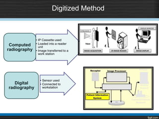
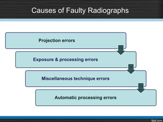
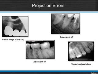
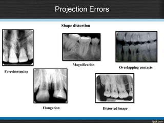
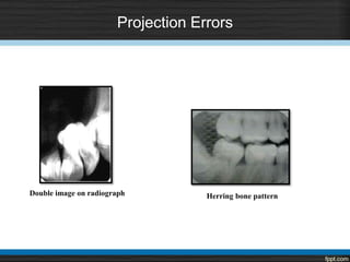
Intraoral Radiographic Processing
and Faults
By: -
Dr. Ruchika Garg
References
 White & Pharoah -Oral Radiology-Principles & Interpretation
(5th & 6th ed.)
 Langland & Langlias -Principles of Dental Imaging
( 2nd ed.)
 Freny R. Karjodkar -Textbook of Dental & Maxillofacial Radiology
( 2nd ed. )
 Haring & Lind - Radiology, Principles & Techniques
( 3rd ed.)
 Eric Waites - Essentials of dental radiography and radiology
(2nd ed.)
 A. Porter , Rochester, N. Y. Radiodontics. Processing technique and difficulties. European Journal of
Radiology. 2002; 1(17)
Contents
• Types of images
• Latent image formation
• Dark room
• Processing of film
• Duplication of films
• Radiographic faults
Types of image
1. Latent image
• Film exposed to beam of photons
• Ag Halide interact with these photons
• Chemically changed
2. Final image
• Chemical changes ↑se liability of crystals to chemical action of
developing process
Latent image formation
Stages in development of latent image
Receiving an exposure
Formation of photoelectron
Migration of electrons
(Acc. to Gurney Mott Theory)
Latent image site
Migration of silver ion
Formation of metallic silver
Latent image
The Darkroom
PROCESSING AREA
VIEWING AREA
Provide a completely darkened
environment
Well ventilated
Dimension – 4ₓ5 feet
Dark Room Equipments
Thermometer:
A thermometer can be left in the master tank to monitor the temperature.
Timer:
An interval timer is indispensable for controlling developing and fixing times.
Drying Racks:
Two or three drying racks with drip trays .
Electric fan is used to circulate air
Master tank - 20 x 25 cm ( 8 x 10 inches )
It serves as a water jacket for two removable inserts to fit inside.
Insert tanks usually hold 1 gallon or 3.8L
Developer insert tank is at left in master tank
Fixer insert tank is at the right in the master tank
Master tank has a cover to protect the solutions from getting oxidized.
Master Tank
Cold
Hot
Mixing valve
Fixer
insert tank
Developer
insert tank
Overflow tube
Drain
Waterbath (large tank)
Water inlet
Darkroom light
White light Safelight
White light
Cleaning tanks & preparing the solutions.
Safe Light
Penny Test
Processing
• Definition - “ A series of steps carried out to make the latent image visible and
ensure it’s permanence. ”
Latent
Image
Steps in Film Processing
Non-exposed film
Developer
Fixer
Rinse
Rinse + Dry
Silver halide
emulsion
Processing solution
1. Developer
2. Fixer
Processing
solutions
Radiographic Developer
• 1. Reducing Agents:
Phenindone + Hydroquinone
• 2. Activator:
Sodium carbonate
• 3. Restrainer:
Potassium bromide / Benzotriazole
• 4. Preservative:
Sodium sulphite
• 5. Solvent:
Water
• 6. Fungicide :
• 7. Buffer :
Developer Replenisher
• 30 periapical or 5 panoramic films
• 8 ounces of fresh developer per gallon of developing solution.
• In order to replenish the solution some amount of old solution is to be discarded.
• Care should be taken in handling the solutions and proper temperature should be
maintained.
Radiographic fixer
• 1. Clearing Agents:
Ammonium thiosulphate or “Hypo”
• 2. Hardener:
Aluminium sulphate or chloride
• 3. Preservative:
Sodium sulphite
• 4. Acidifier:
Acetic acid
• 5. Solvent:
Water
Functions of Fixer
To dissolve and remove the unexposed Silver Halide crystals
from film emulsion.
To harden and shrink the film emulsion
Intensification of Radiographs
• Indications :
• Light radiographs
• Act by –
• Converting the silver into a more radio-opaque compound
• Time required – 3-8 mins
• Commercially available solutions –
• In-4 Chromium intensifier
• In-5 Silver intensifier
• Copper iodide intensifying solution
• XR-10 intensifying solution
Rinsing
Ensures the removal of Thiosulphate ions and its
compounds.
The temperature should be maintained to 60o F below
which its efficiency declines
Should be done under running water.
Methods of Processing
Manual Automatic Daylight Monobath
Self developing Digitized
Time temperature method
Visual method
Rapid processing
chemicals
Time Temperature Method
STEPS:
1. Identify the solutions
2. Replenish and stir them
3. Labeling the film hanger
4. Mount films on hangers
Time Temperature Method
5. Setting a development time
TEMPERATURE DEVELOPMENT TIME
68o F 5-6 minutes
70o F 4-5 minutes
72o F 3-4 minutes
76o F 2-3 minutes
80o F 1-2 minutes
Time Temperature Method
6. Removing film from the
packet
7. Holding the film with hanger
8. Developing the film
9. Rinsing
10. Fixing
11. Washing + Drying
• Visual method
Viewing from time to time
• Rapid processing chemicals
Develops in 15 secs at room temperature
Resultant images – decreased contrast ; may discolor over a period of time
Automatic Film Processing
Roller film
transporter
Developer
compartement
Film feed
slot
Processor
Housing
Fixer
compartement
Water
compartement
Drying
chamber
Film
slot
Replenisher
pump
Replenisher
solutions
Automatic Film Processing
Advantages Disadvantages
1. Standardized 1. Maintenance of processor
2. Darkroom not required 2. Expensive
3. Less space
4. No wet films, hangers or driers
5. Time saving
Daylight Processing Method
• Both Manual and Automatic processing can be executed in this manner.
• Manual daylight processing involves stripping the film inside a light proof
pouch. Within the pouch itself, the stripped films are inserted in and processing
steps are carried out manually
• Automatic processor has a daylight loading chamber
• The entire assembly is enclosed in a light proof container
• Elimination of need for a darkroom is the only advantage of this method.
Self-Developing Method
Film present in a special sachet containing developer
and fixer
Advantages –
No darkroom required
Time saving
Disadvantages –
Poor image quality
Rapid image deteoration
Film packet – flexible and easily bent
Relatively expensive
Monobath Method
 Fill syringe with 2 ml of monobath solution.
 Insert into the top of the packet and inject.
 Gently massage film packet for 80 seconds.
 Open the film packet, and rinse for 2 minutes.
Digitized Method
• IP Cassette used
• Loaded into a reader
unit
• Image transferred to a
work station
Computed
radiography
• Sensor used
• Connected to
workstation
Digital
radiography
Duplication of Radiograph
Duplicating film
 Sensitive to UV light
 No orientation dot present
 Letter L or R to be written
 Photographic printing frame
Requirement for duplicating film
 Allow patient to take films to many different locations, keeping original at hospital
 Extra set for teaching purposes
 It is often necessary to send a copy of films to another general practitioner or a specialist
 Also to obtain a preauthorization from the insurance company.
Precautions –
 Correctly labelled
 Should be checked clinically with the patient
 Should be kept in light tight room
Methods of Duplicating Radiograph
a. Photographic
method
b. Double
film packet
c. Radiographic
method
d. Solarization
method
e. Electronic
duplicating
apparatus
Neill Serman. Duplicating Radiographs. Sept. 2000.
Causes of Faulty Radiographs
Projection errors
Exposure & processing errors
Miscellaneous technique errors
Automatic processing errors
Projection Errors
Partial image (Cone cut)
Crowns cut off
Apices cut off
Tipped occlusal plane
Projection Errors
Overlapping contacts
Foreshortening
Elongation
Shape distortion
Distorted image
Magnification
Projection Errors
Herring bone patternDouble image on radiograph
Projection Errors
Blurring
Cervical burn out
Exposure & Processing Errors
Clear radiograph Black radiograph
Exposure & Processing Errors
Light radiograph
a. Under exposure
b. Under development
c. Excessive fixation
Dark radiograph
a. Over exposure
b. Over development
c. Under fixation
Exposure & Processing Errors
Black spots
Reticulation
Contamination with dust
Splashing with developer
•Sudden temperature changes
•Weakened fixer solution
Exposure & Processing Errors
White spots
Black lines
Film creasing
Static electricity – Spark caused by low
potential electric discharge
Contamination with fixer
Rough handling
Exposure & Processing Errors
Streaks on film
Film fog
Inappropriate safe light
High developer temperature
Failure to agitate during developing
Excessive drying
Chemical deposits on clips
Insufficient fixation
Exposure & Processing Errors
Yellow brown stains
Emulsion peel
Excessive washing
Abrasion of image
Exhausted developer
Prolonged developing
Insufficient rinsing
Contaminated solutions
Exposure & Processing Errors
Light leak
Developer cut-off
Fixer cut-off
Film crease
Exposure & Processing Errors
Miscellaneous
Phalangioma
Automatic Processing Errors
Film density Problems
a. Decrease in film density
b. Increase in film density
Low temperature
Exhausted developer
Contaminated developer
High developer temperature
Strong developer
Light leaks
Automatic Processing Errors
Abnormal film surface marks
a. Peeling of the emulsion
b. Scratches on film surface
High developer temperature
Depleted fixer
Rough handling prior to processing
Foreign material on rollers
Sticking rollers
Automatic processing errors
Exhausted developer or fixer
Partial fixation
Cloudy appearance
Radiographic artifacts
New Updates
DFL Contrast FV-58 film has stable properties when exhausted manual processing
solutions are used and can be recommended for use in dental practice, contributing to
dose reduction.
Conclusion
• Every radiographic examination should produce radiographs of optimal
diagnostic quality.
• Radiographs should record the complete area of interest and should have
minimal possible distortion.
• Improper positioning of receptor and x-ray tube and faulty processing can
adversely affect the quality of a properly exposed radiograph.
• Thus close attention should be paid to optimize these parameters.
Intraoral radiographic processing and faults

Intraoral radiographic processing and faults

  • 1.
    Intraoral Radiographic Processing andFaults By: - Dr. Ruchika Garg
  • 2.
    References  White &Pharoah -Oral Radiology-Principles & Interpretation (5th & 6th ed.)  Langland & Langlias -Principles of Dental Imaging ( 2nd ed.)  Freny R. Karjodkar -Textbook of Dental & Maxillofacial Radiology ( 2nd ed. )  Haring & Lind - Radiology, Principles & Techniques ( 3rd ed.)  Eric Waites - Essentials of dental radiography and radiology (2nd ed.)  A. Porter , Rochester, N. Y. Radiodontics. Processing technique and difficulties. European Journal of Radiology. 2002; 1(17)
  • 3.
    Contents • Types ofimages • Latent image formation • Dark room • Processing of film • Duplication of films • Radiographic faults
  • 4.
    Types of image 1.Latent image • Film exposed to beam of photons • Ag Halide interact with these photons • Chemically changed 2. Final image • Chemical changes ↑se liability of crystals to chemical action of developing process
  • 5.
  • 6.
    Stages in developmentof latent image Receiving an exposure Formation of photoelectron Migration of electrons (Acc. to Gurney Mott Theory)
  • 7.
    Latent image site Migrationof silver ion Formation of metallic silver
  • 8.
  • 9.
    The Darkroom PROCESSING AREA VIEWINGAREA Provide a completely darkened environment Well ventilated Dimension – 4ₓ5 feet
  • 10.
    Dark Room Equipments Thermometer: Athermometer can be left in the master tank to monitor the temperature. Timer: An interval timer is indispensable for controlling developing and fixing times. Drying Racks: Two or three drying racks with drip trays . Electric fan is used to circulate air
  • 11.
    Master tank -20 x 25 cm ( 8 x 10 inches ) It serves as a water jacket for two removable inserts to fit inside. Insert tanks usually hold 1 gallon or 3.8L Developer insert tank is at left in master tank Fixer insert tank is at the right in the master tank Master tank has a cover to protect the solutions from getting oxidized.
  • 12.
    Master Tank Cold Hot Mixing valve Fixer inserttank Developer insert tank Overflow tube Drain Waterbath (large tank) Water inlet
  • 13.
  • 14.
    White light Cleaning tanks& preparing the solutions.
  • 15.
  • 16.
  • 18.
    Processing • Definition -“ A series of steps carried out to make the latent image visible and ensure it’s permanence. ” Latent Image
  • 19.
    Steps in FilmProcessing Non-exposed film Developer Fixer Rinse Rinse + Dry Silver halide emulsion
  • 20.
    Processing solution 1. Developer 2.Fixer Processing solutions
  • 21.
    Radiographic Developer • 1.Reducing Agents: Phenindone + Hydroquinone • 2. Activator: Sodium carbonate • 3. Restrainer: Potassium bromide / Benzotriazole • 4. Preservative: Sodium sulphite • 5. Solvent: Water • 6. Fungicide : • 7. Buffer :
  • 22.
    Developer Replenisher • 30periapical or 5 panoramic films • 8 ounces of fresh developer per gallon of developing solution. • In order to replenish the solution some amount of old solution is to be discarded. • Care should be taken in handling the solutions and proper temperature should be maintained.
  • 23.
    Radiographic fixer • 1.Clearing Agents: Ammonium thiosulphate or “Hypo” • 2. Hardener: Aluminium sulphate or chloride • 3. Preservative: Sodium sulphite • 4. Acidifier: Acetic acid • 5. Solvent: Water
  • 24.
    Functions of Fixer Todissolve and remove the unexposed Silver Halide crystals from film emulsion. To harden and shrink the film emulsion
  • 25.
    Intensification of Radiographs •Indications : • Light radiographs • Act by – • Converting the silver into a more radio-opaque compound • Time required – 3-8 mins • Commercially available solutions – • In-4 Chromium intensifier • In-5 Silver intensifier • Copper iodide intensifying solution • XR-10 intensifying solution
  • 26.
    Rinsing Ensures the removalof Thiosulphate ions and its compounds. The temperature should be maintained to 60o F below which its efficiency declines Should be done under running water.
  • 27.
    Methods of Processing ManualAutomatic Daylight Monobath Self developing Digitized Time temperature method Visual method Rapid processing chemicals
  • 28.
    Time Temperature Method STEPS: 1.Identify the solutions 2. Replenish and stir them 3. Labeling the film hanger 4. Mount films on hangers
  • 29.
    Time Temperature Method 5.Setting a development time TEMPERATURE DEVELOPMENT TIME 68o F 5-6 minutes 70o F 4-5 minutes 72o F 3-4 minutes 76o F 2-3 minutes 80o F 1-2 minutes
  • 30.
    Time Temperature Method 6.Removing film from the packet 7. Holding the film with hanger 8. Developing the film 9. Rinsing 10. Fixing 11. Washing + Drying
  • 31.
    • Visual method Viewingfrom time to time • Rapid processing chemicals Develops in 15 secs at room temperature Resultant images – decreased contrast ; may discolor over a period of time
  • 32.
    Automatic Film Processing Rollerfilm transporter Developer compartement Film feed slot Processor Housing Fixer compartement Water compartement Drying chamber Film slot Replenisher pump Replenisher solutions
  • 33.
    Automatic Film Processing AdvantagesDisadvantages 1. Standardized 1. Maintenance of processor 2. Darkroom not required 2. Expensive 3. Less space 4. No wet films, hangers or driers 5. Time saving
  • 34.
    Daylight Processing Method •Both Manual and Automatic processing can be executed in this manner. • Manual daylight processing involves stripping the film inside a light proof pouch. Within the pouch itself, the stripped films are inserted in and processing steps are carried out manually • Automatic processor has a daylight loading chamber • The entire assembly is enclosed in a light proof container • Elimination of need for a darkroom is the only advantage of this method.
  • 35.
    Self-Developing Method Film presentin a special sachet containing developer and fixer Advantages – No darkroom required Time saving Disadvantages – Poor image quality Rapid image deteoration Film packet – flexible and easily bent Relatively expensive
  • 36.
    Monobath Method  Fillsyringe with 2 ml of monobath solution.  Insert into the top of the packet and inject.  Gently massage film packet for 80 seconds.  Open the film packet, and rinse for 2 minutes.
  • 37.
    Digitized Method • IPCassette used • Loaded into a reader unit • Image transferred to a work station Computed radiography • Sensor used • Connected to workstation Digital radiography
  • 38.
    Duplication of Radiograph Duplicatingfilm  Sensitive to UV light  No orientation dot present  Letter L or R to be written  Photographic printing frame Requirement for duplicating film  Allow patient to take films to many different locations, keeping original at hospital  Extra set for teaching purposes  It is often necessary to send a copy of films to another general practitioner or a specialist  Also to obtain a preauthorization from the insurance company. Precautions –  Correctly labelled  Should be checked clinically with the patient  Should be kept in light tight room
  • 39.
    Methods of DuplicatingRadiograph a. Photographic method b. Double film packet c. Radiographic method d. Solarization method e. Electronic duplicating apparatus Neill Serman. Duplicating Radiographs. Sept. 2000.
  • 41.
    Causes of FaultyRadiographs Projection errors Exposure & processing errors Miscellaneous technique errors Automatic processing errors
  • 42.
    Projection Errors Partial image(Cone cut) Crowns cut off Apices cut off Tipped occlusal plane
  • 43.
  • 44.
    Projection Errors Herring bonepatternDouble image on radiograph
  • 45.
  • 46.
    Exposure & ProcessingErrors Clear radiograph Black radiograph
  • 47.
    Exposure & ProcessingErrors Light radiograph a. Under exposure b. Under development c. Excessive fixation Dark radiograph a. Over exposure b. Over development c. Under fixation
  • 48.
    Exposure & ProcessingErrors Black spots Reticulation Contamination with dust Splashing with developer •Sudden temperature changes •Weakened fixer solution
  • 49.
    Exposure & ProcessingErrors White spots Black lines Film creasing Static electricity – Spark caused by low potential electric discharge Contamination with fixer Rough handling
  • 50.
    Exposure & ProcessingErrors Streaks on film Film fog Inappropriate safe light High developer temperature Failure to agitate during developing Excessive drying Chemical deposits on clips Insufficient fixation
  • 51.
    Exposure & ProcessingErrors Yellow brown stains Emulsion peel Excessive washing Abrasion of image Exhausted developer Prolonged developing Insufficient rinsing Contaminated solutions
  • 52.
    Exposure & ProcessingErrors Light leak Developer cut-off Fixer cut-off
  • 53.
    Film crease Exposure &Processing Errors
  • 54.
  • 55.
    Automatic Processing Errors Filmdensity Problems a. Decrease in film density b. Increase in film density Low temperature Exhausted developer Contaminated developer High developer temperature Strong developer Light leaks
  • 56.
    Automatic Processing Errors Abnormalfilm surface marks a. Peeling of the emulsion b. Scratches on film surface High developer temperature Depleted fixer Rough handling prior to processing Foreign material on rollers Sticking rollers
  • 57.
    Automatic processing errors Exhausteddeveloper or fixer Partial fixation Cloudy appearance
  • 58.
  • 59.
    New Updates DFL ContrastFV-58 film has stable properties when exhausted manual processing solutions are used and can be recommended for use in dental practice, contributing to dose reduction.
  • 60.
    Conclusion • Every radiographicexamination should produce radiographs of optimal diagnostic quality. • Radiographs should record the complete area of interest and should have minimal possible distortion. • Improper positioning of receptor and x-ray tube and faulty processing can adversely affect the quality of a properly exposed radiograph. • Thus close attention should be paid to optimize these parameters.

Editor's Notes

  • #5 When a beam of photons exits an object and exposes an x-ray film, it chemically changes the photosensitive silver halide crystals in the film emulsion. These chemically altered silver bromide crystals constitute the latent image.
  • #6 The crystals are chemically sensitized by addition of trace amount of sulfur compounds, which bind to the surface of these crystals. Sulfur compounds create sensitivity sites, the sites in the crystals that are sensitive to radiation. This process occurs numerous times within the crystal. These sites that contain the neutral silver atoms are now called latent image sites. The overall distribution of the latent image sites in a film after exposure constitutes the latent image. The neutral silver atoms at each latent image site render the crystals sensitive to development and image formation.
  • #21 Film processing refers to the entire procedure of conversion of the latent image to a visible image and preservation of the visible image. Developer solution converts the sensitized silver halide crystals into black, solid silver metallic grains. Fixer removes the unexposed, undeveloped silver bromide crystals leaving the film clear in unexposed sites.
  • #35 Any processing method that does not need a darkroom, i
  • #39 Radiograph to be duplicated should be in close contact with the emulsion side – hold the duplicating film against the original Film is exposed to light for about 6-8 secs
  • #42 Poor radiographs contribute to loss of diagnostic information and loss of professional and patient time.