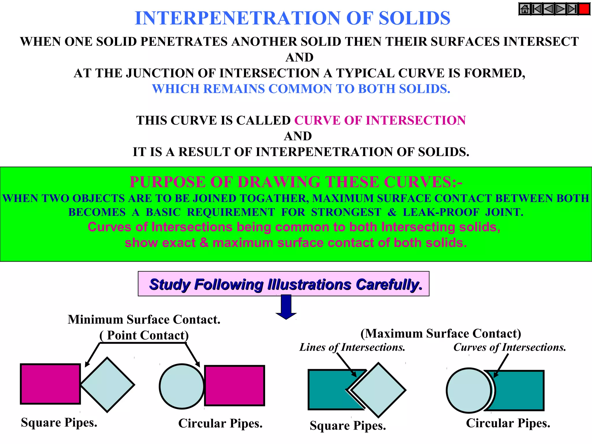
1. When two solids intersect, their surfaces meet along a common curve called the curve of intersection. This curve shows the maximum surface contact between the solids and is important for making strong, leak-proof joints.
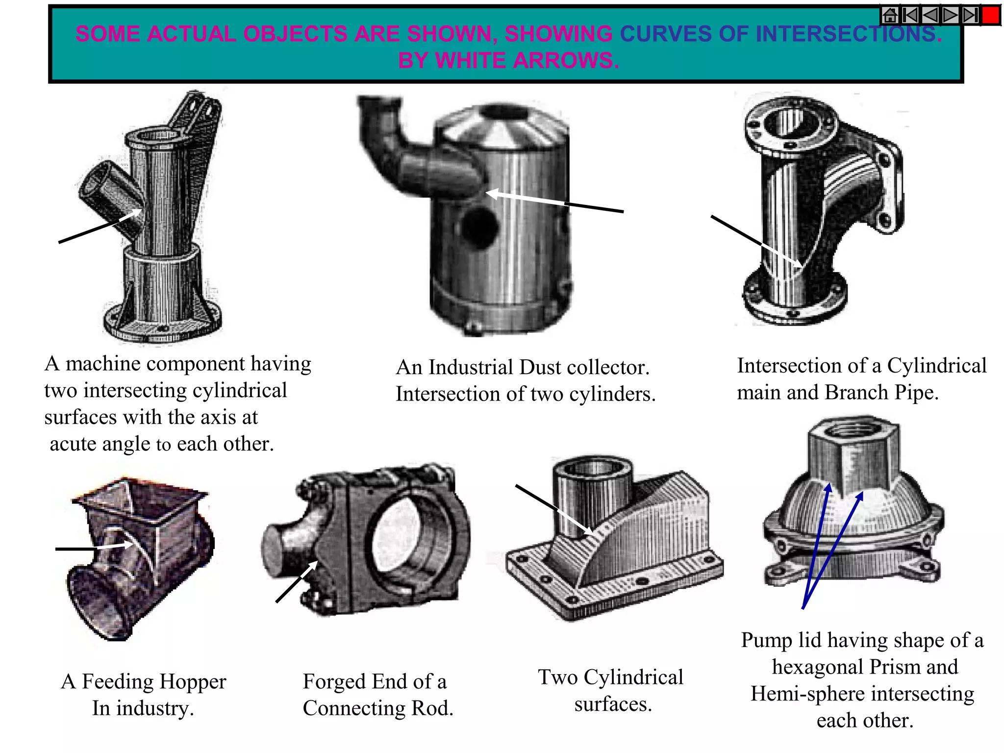
2. The document provides examples of curves of intersection for different geometric solids intersecting in various configurations, such as cylinders, prisms, cones, and other industrial parts.
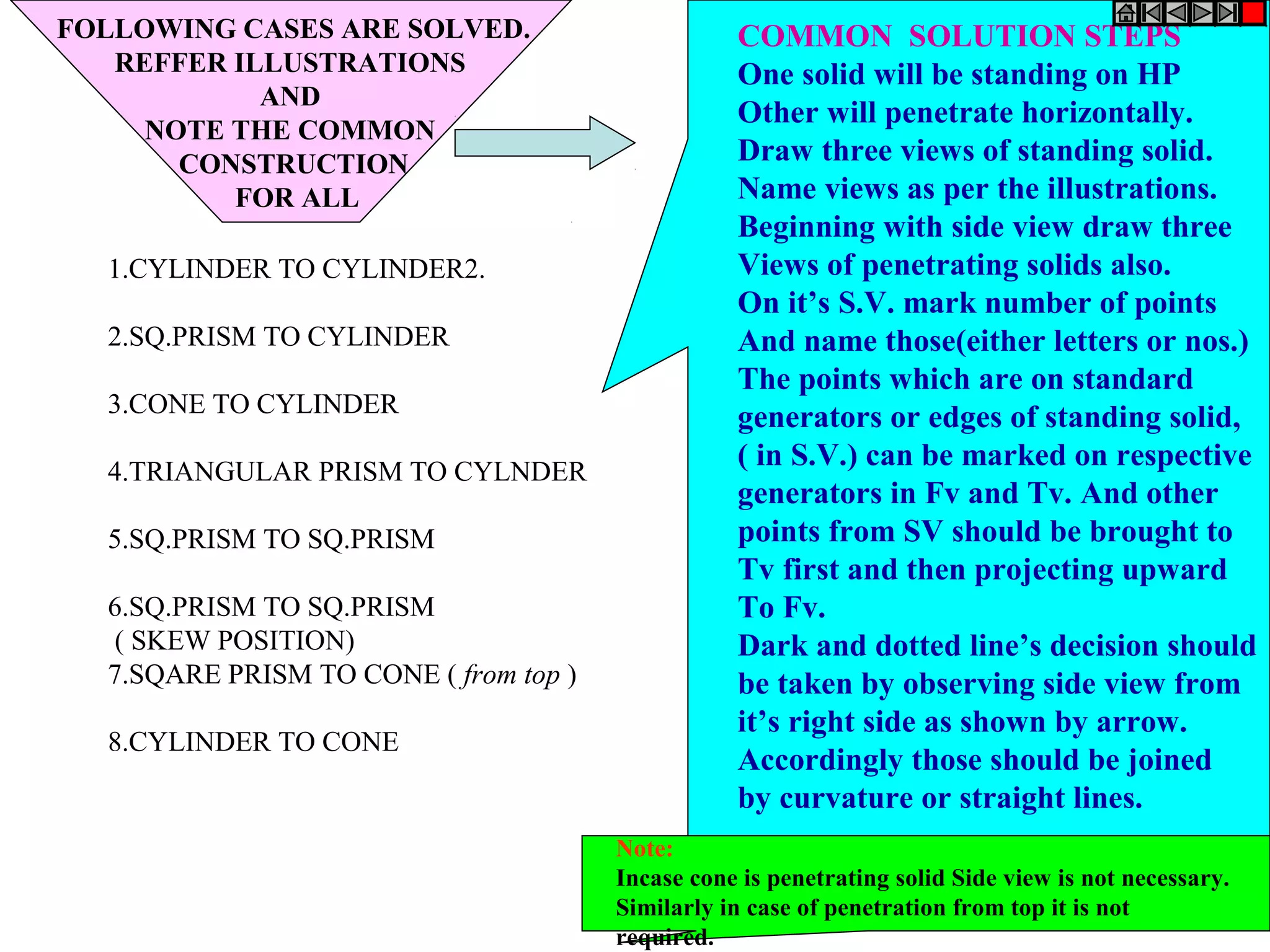
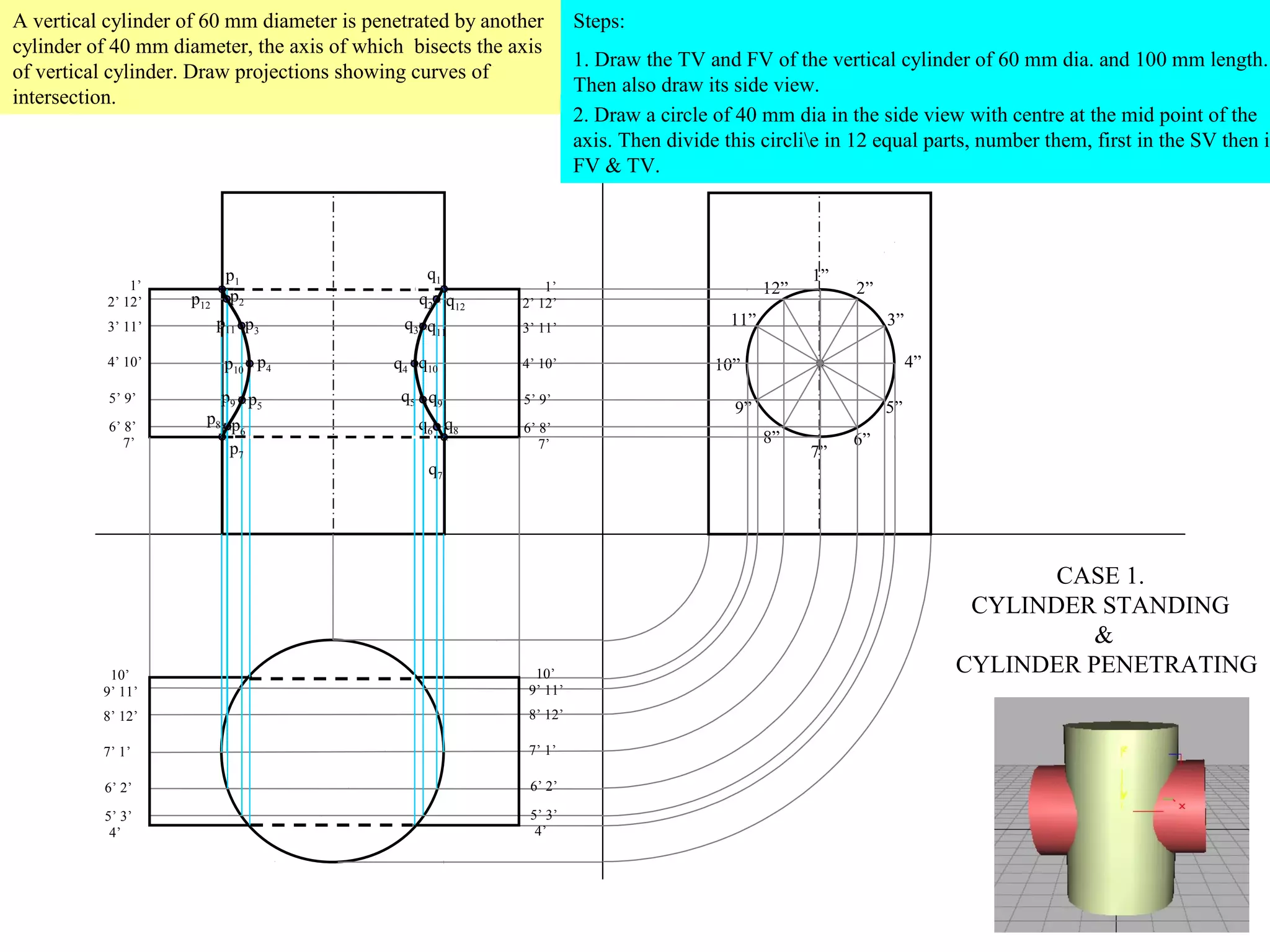
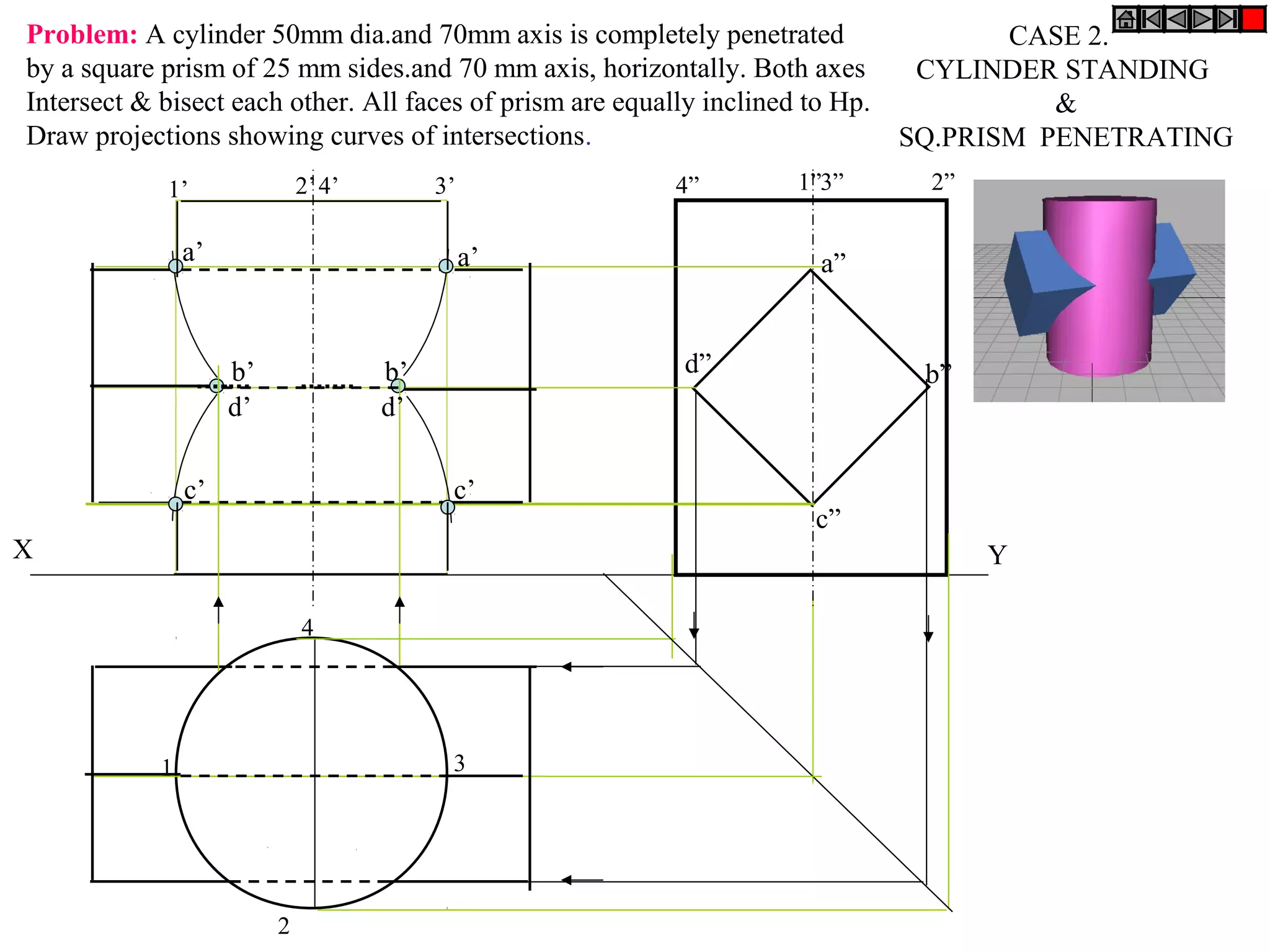
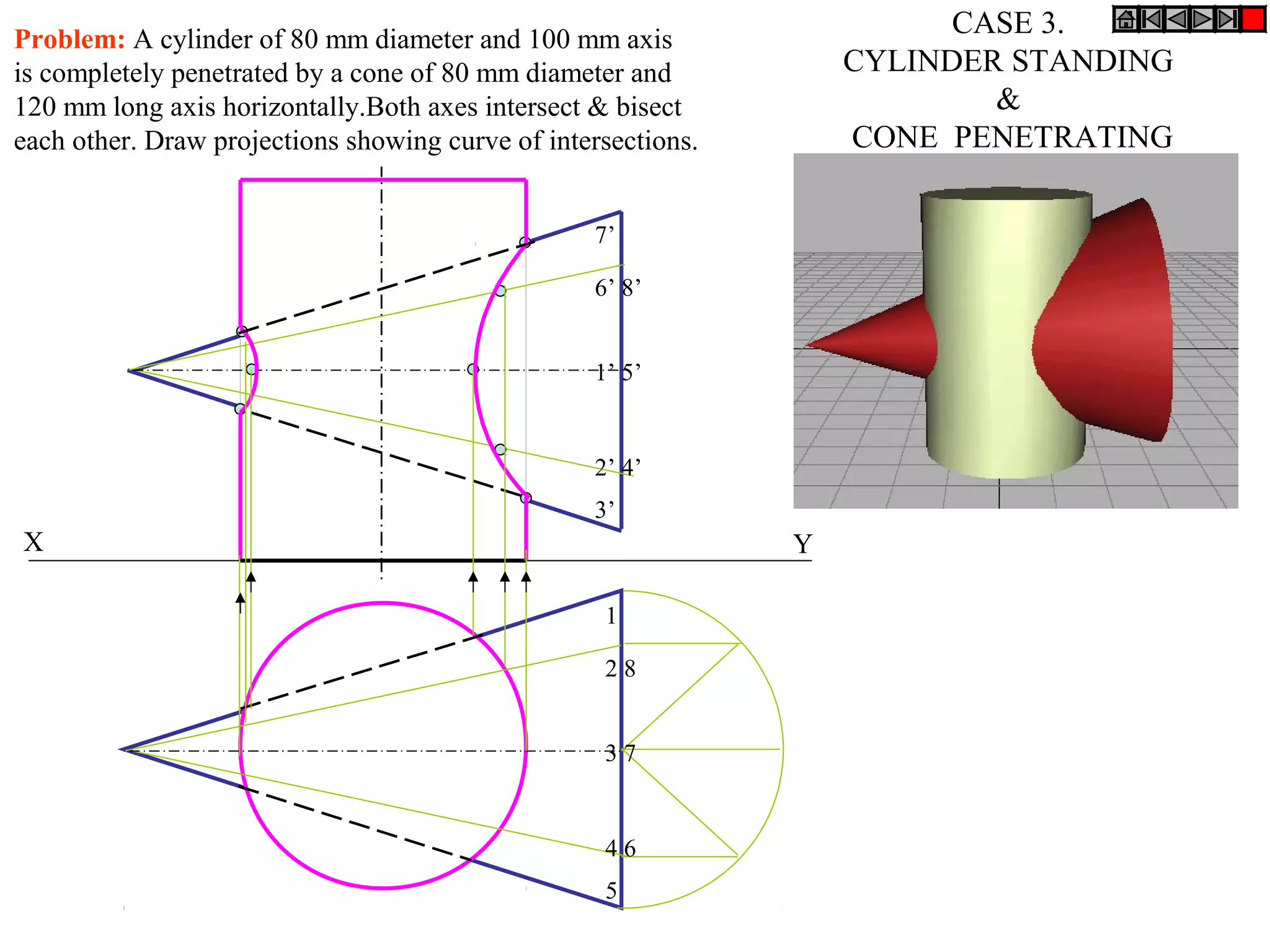
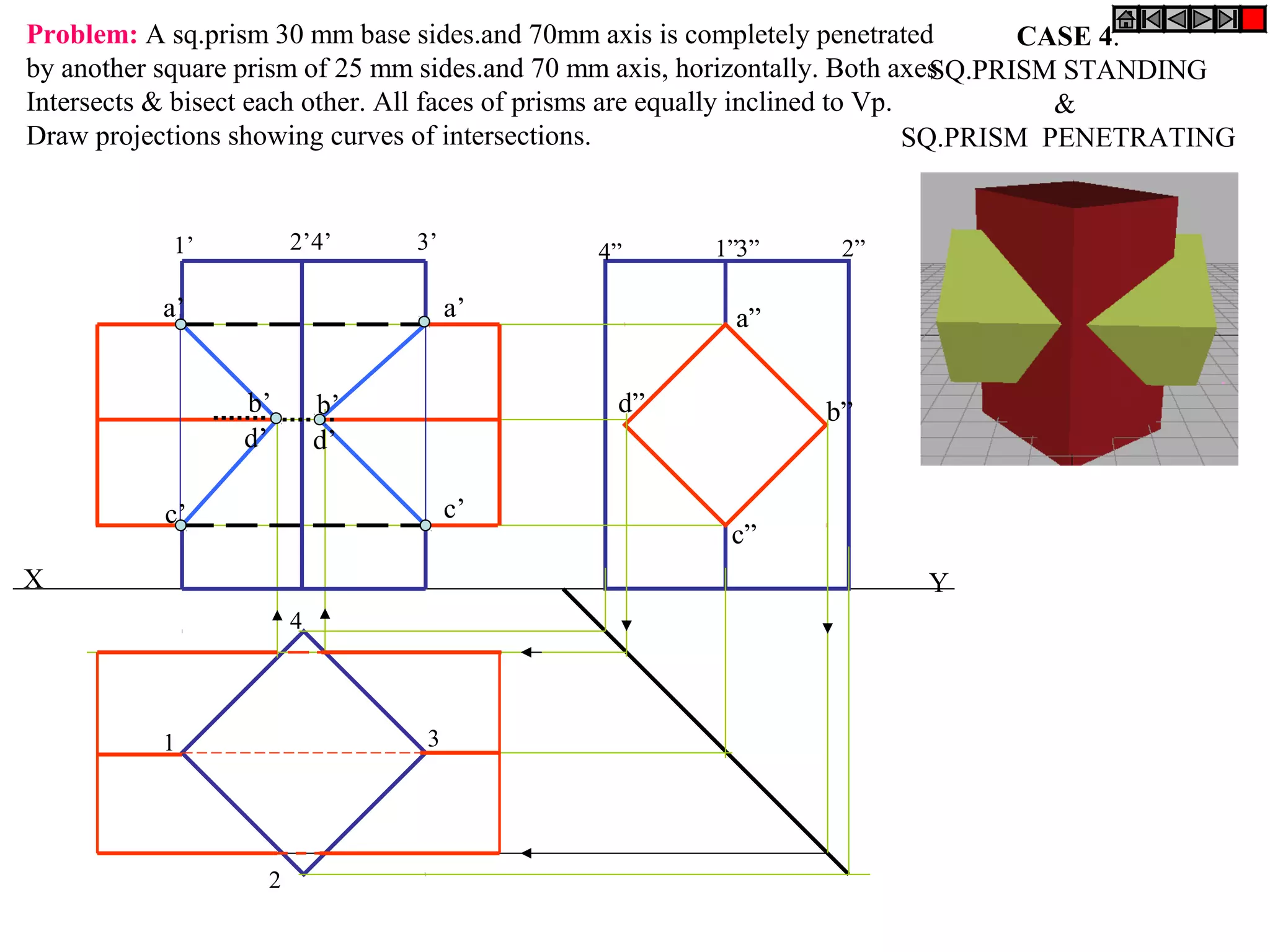
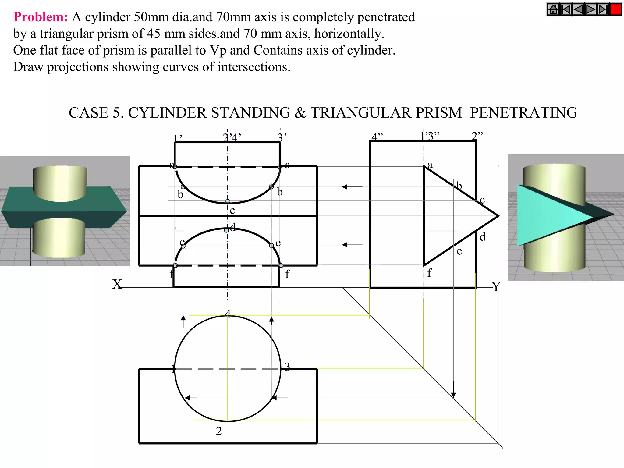
3. Step-by-step procedures are described for drawing the projections of the solids and determining the curves of intersection in different cases, including cylinders penetrating cylinders, prisms penetrating cylinders, cones penetrating cylinders, and other configurations.
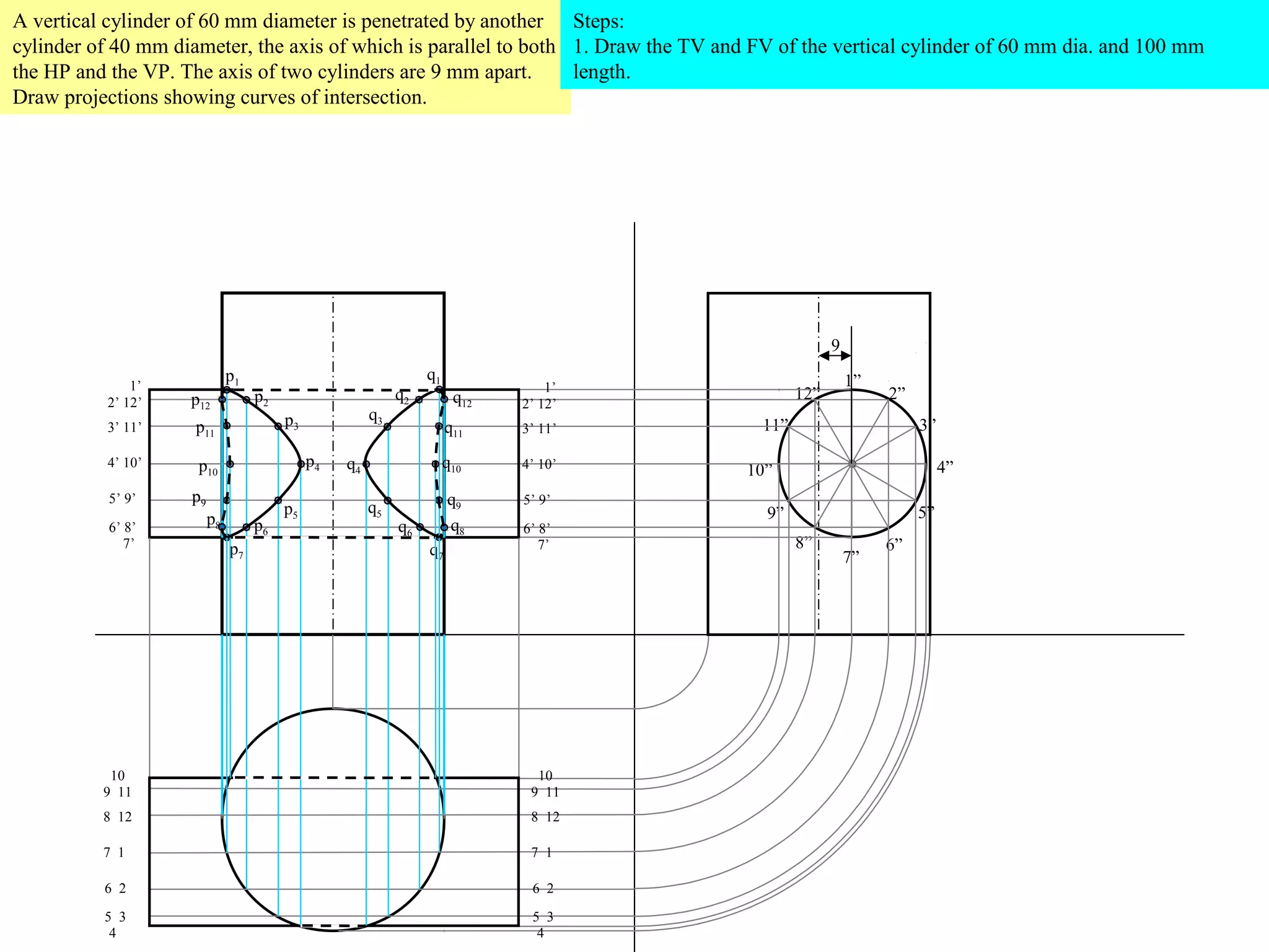
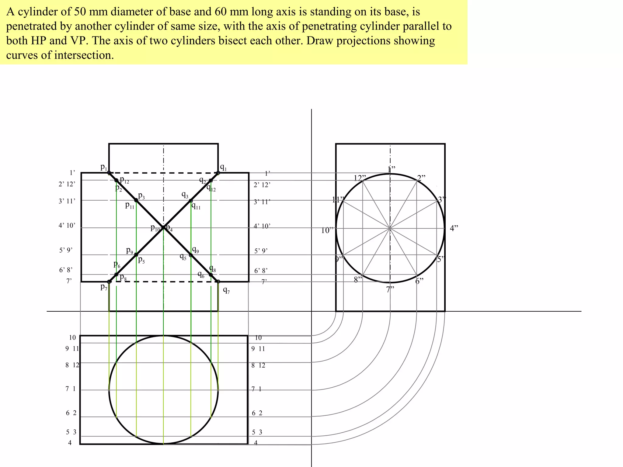
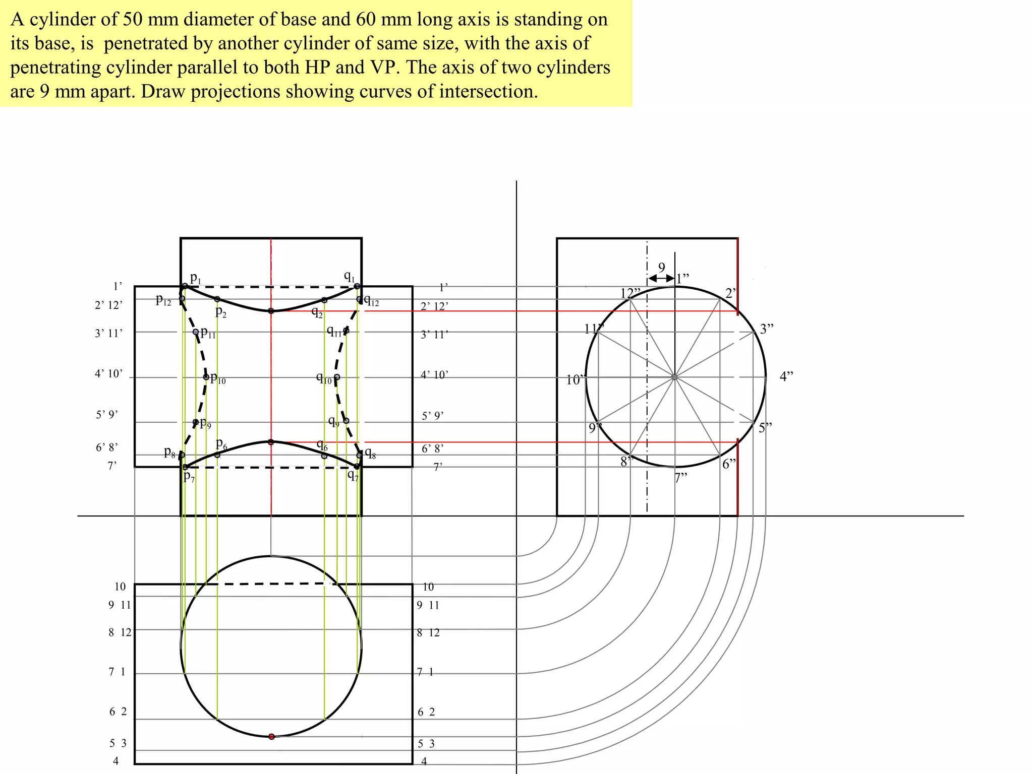
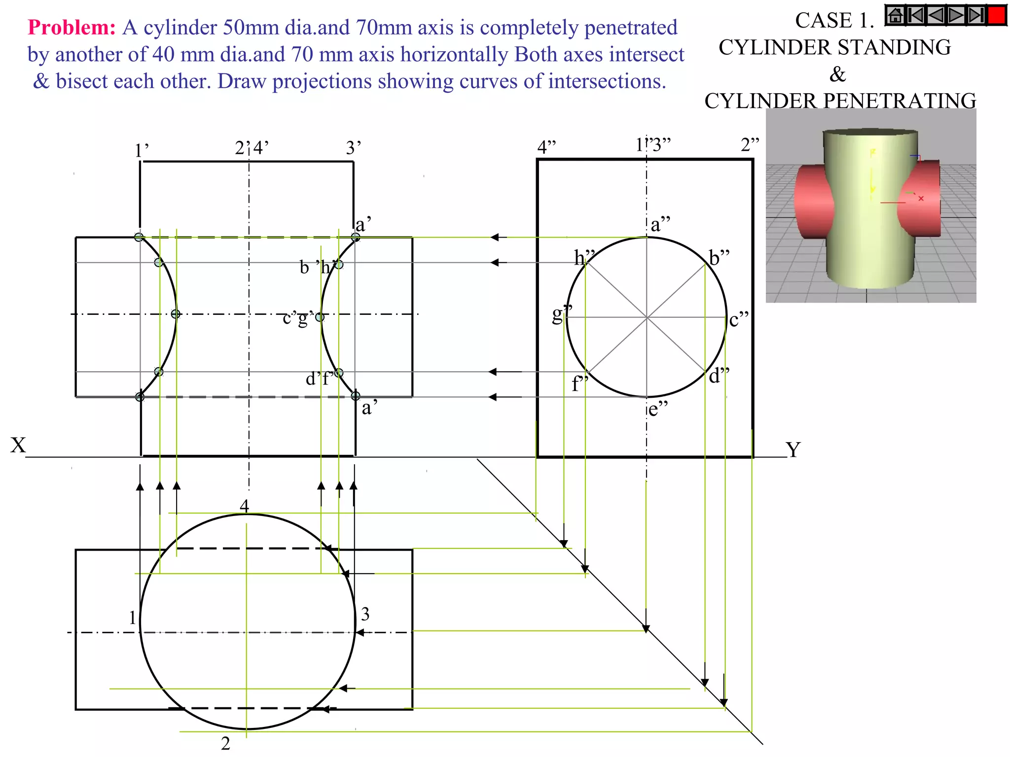
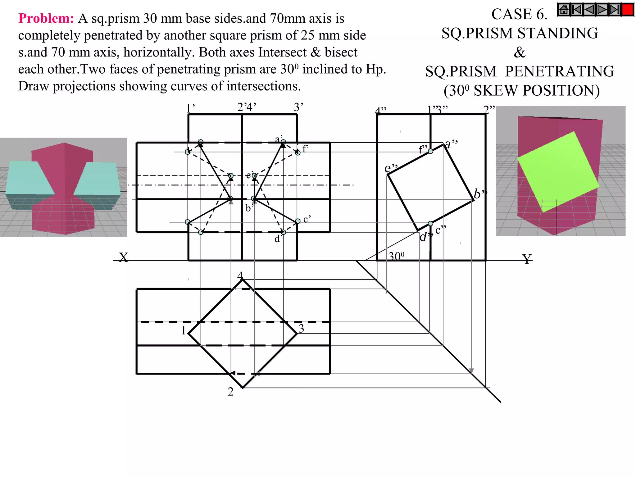
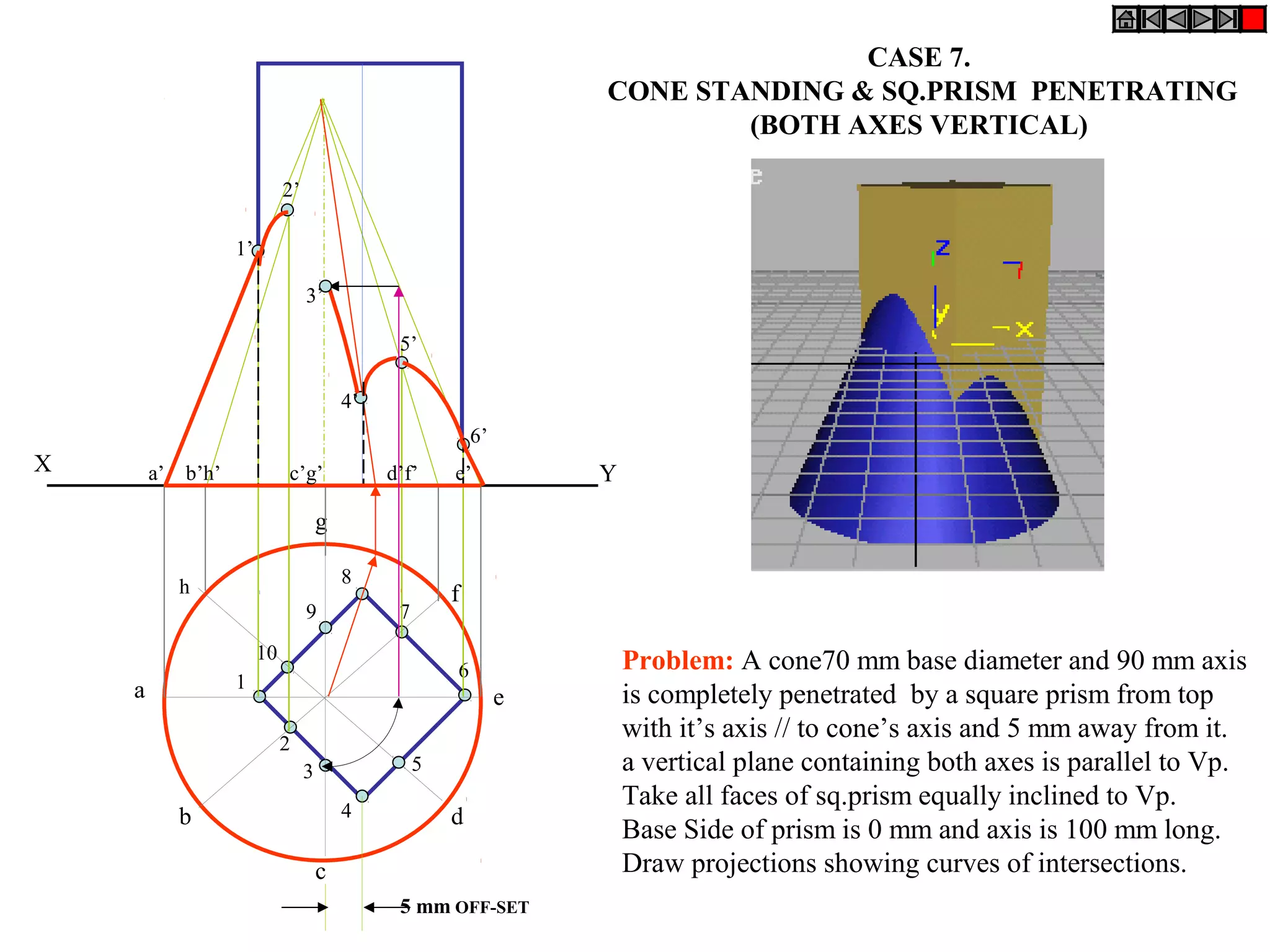


![Coded Agents – with UiPath SDK + LangGraph [Virtual Hands-on Workshop]](https://cdn.slidesharecdn.com/ss_thumbnails/codedagentsdeck-251215155422-5497c599-thumbnail.jpg?width=640&height=640&fit=bounds)


