OBJECTIVES What isinterpenetration of
solids
Importance of
interpenetration
Methods for interpenetration
Lines or curves of intersection
Cases of interpenetration
2
3.
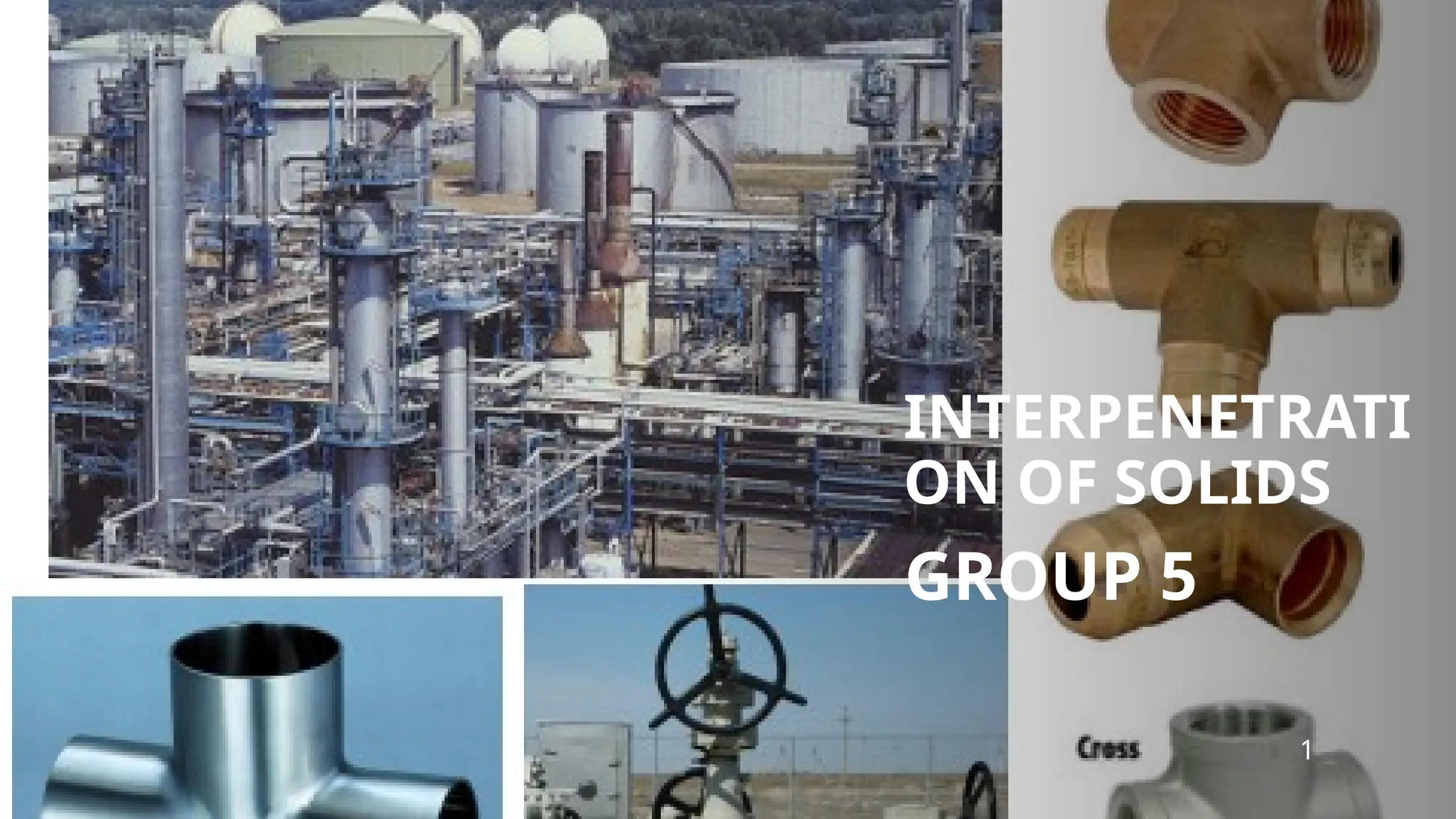
INTERPENETRATION OF SOLIDS
Itrefers to the intersection or overlap of two or
more surfaces in 3D space.
When one solid penetrates another solid then
their surfaces intersect and at the junction of
intersection a typical curve is formed which
remains common to both sides.
NB;This curve is called a curve of intersection
(COI) and it’s as result of a interpenetration of
solids
3
4.
IMPORTANCE OF INTERPENETRATION
Understandingcurves of intersection is essential for designing and
leak –proof joint between objects, ensuring proper surface contact.
Ducts, pipe joints ,smokestacks ,boilers ,containers , machine
castings etc. , involve intersection of surfaces
Engineers in charge of fabrication must first determine accurately
the curve of intersection of the two elements and then prepare the
development of the two elements on the bases of the curve of
penetration.
5.
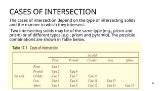
CASES OF INTERSECTION
Thecases of intersection depend on the type of intersecting solids
and the manner in which they intersect.
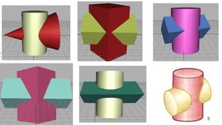
Two intersecting solids may be of the same type (e.g., prism and
prism) or of different types (e.g., prism and pyramid). The possible
combinations are shown in Table below.
4
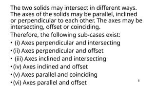
The two solidsmay intersect in different ways.
The axes of the solids may be parallel, inclined
or perpendicular to each other. The axes may be
intersecting, offset or coinciding.
Therefore, the following sub-cases exist:
• (i) Axes perpendicular and intersecting
•(ii) Axes perpendicular and offset
• (iii) Axes inclined and intersecting
•(iv) Axes inclined and offset
•(v) Axes parallel and coinciding
•(vi) Axes parallel and offset
6
8.
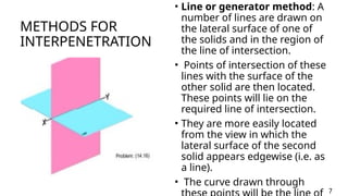
METHODS FOR
INTERPENETRATION
• Lineor generator method: A
number of lines are drawn on
the lateral surface of one of
the solids and in the region of
the line of intersection.
• Points of intersection of these
lines with the surface of the
other solid are then located.
These points will lie on the
required line of intersection.
• They are more easily located
from the view in which the
lateral surface of the second
solid appears edgewise (i.e. as
a line).
• The curve drawn through
7
9.
METHODS OF INTERPENETRATION
•Cutting-plane method: The two solids are assumed to be
cut by a series of cutting planes.
• The cutting planes may be vertical (i.e. perpendicular to the
H.P.), edgewise (i.e. perpendicular to the V.P.) or oblique.
• The cutting planes are so selected as to cut the surface of
one of the solids in straight lines and that of the other in
straight lines or circles.
8
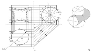
Imagine Cutting Planes:
Considera series of cutting planes that intersect both solids. These
planes can be parallel to a reference plane (like the horizontal or vertical
plane) or inclined at an angle.
Locate Intersection Lines:
For each cutting plane, determine where it intersects the edges of each
solid. This will form a series of lines where the plane cuts through the
solid's surfaces.
Find Piercing Points:
Identify the points where the intersection lines from the two solids
meet. These are the piercing points.
Project and Connect:
Project these piercing points onto the other views (e.g., plan, elevation,
side view) to locate their corresponding positions in those
views. Connect the projected piercing points to form the intersection
curve in each view.
Repeat and Refine:
Repeat steps 2-4 for each cutting plane. The more cutting planes used,
the more accurate the representation of the intersection curve will be.
CUTTING PLANE METHOD
11
REFERENCES
Dhawan, R. K.(2019). A textbook of engineering drawing in first
˜ œ
angle projection : (for B.E./B.Tech. students of different
technological universities of India).
S. Chand Publishing.Simmons, C. H., Maguire, D. E., & Phelps,
N. (2009). Manual of engineering drawing. Elsevier.Singh
L. P., & Singh, H. (2021). Engineering Drawing. Cambridge
University Press.
1
15.
GROUP MEMBERS
Josiah Agyei
HerbertAmponsah
Courage Attiye
Ernest Donkor
John Amissah
Christian Mensah Okyere
Justice Osei Yeboah
Abraham Asempa