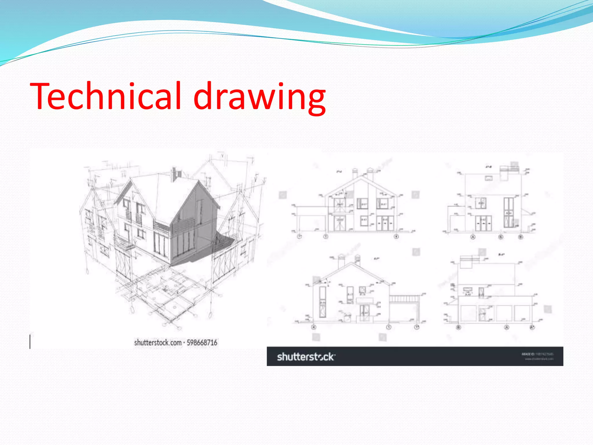
Technical drawing uses standardized visual conventions and symbols to unambiguously communicate engineering and design concepts. It is considered essential for industry. The international standard ISO 128 codifies common principles, such as types of lines and projection views. Technical drawing aims for objective, single interpretations compared to the subjective nature of artistic drawing. Draftspeople create technical drawings according to standardized guidelines for dimensions, projections, and different line types that indicate visible, hidden, cut, and other features of a design.


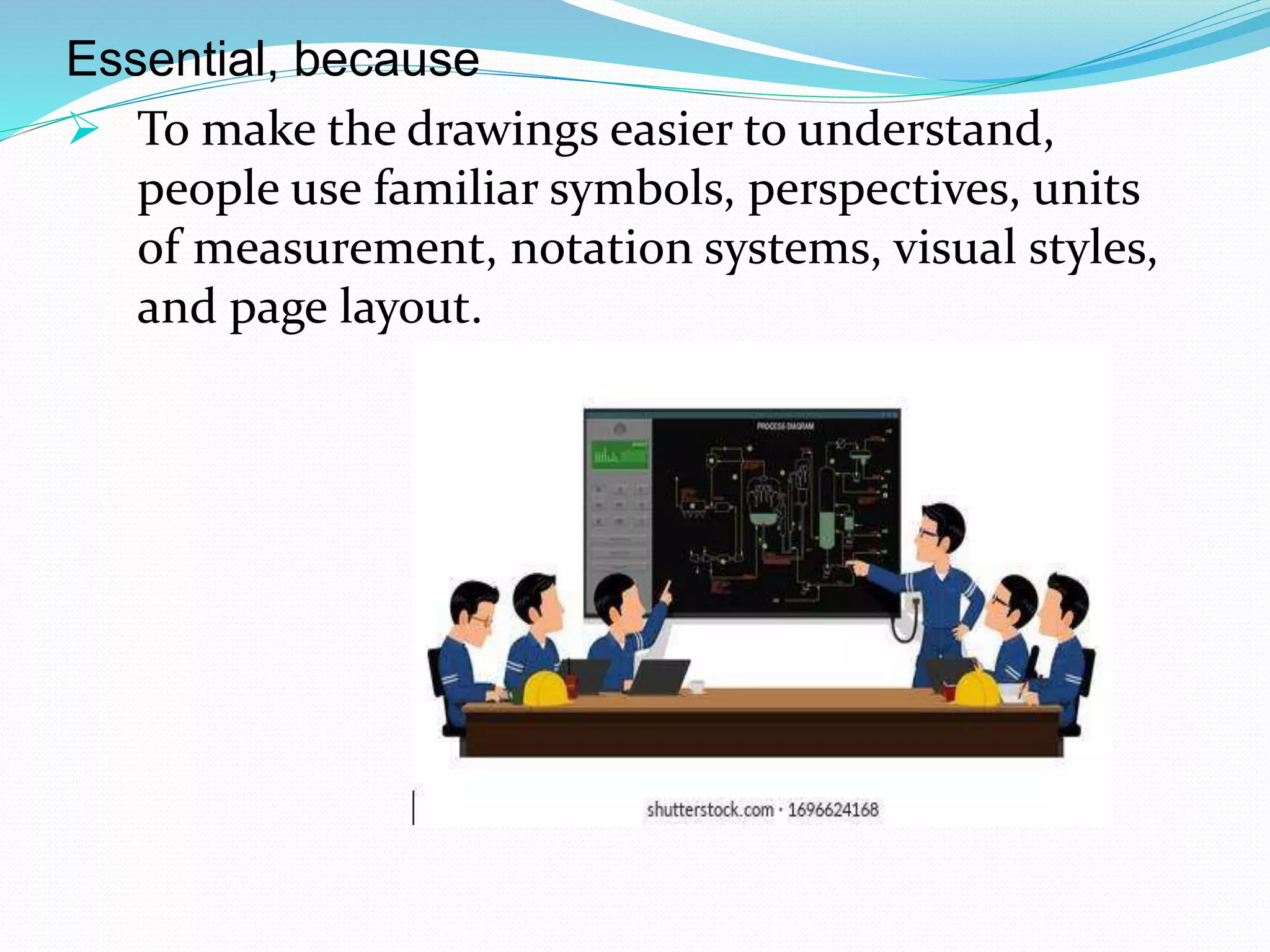
![ Together, such conventions constitute a visual language and help
to ensure that the drawing is unambiguous and relatively easy to
understand.
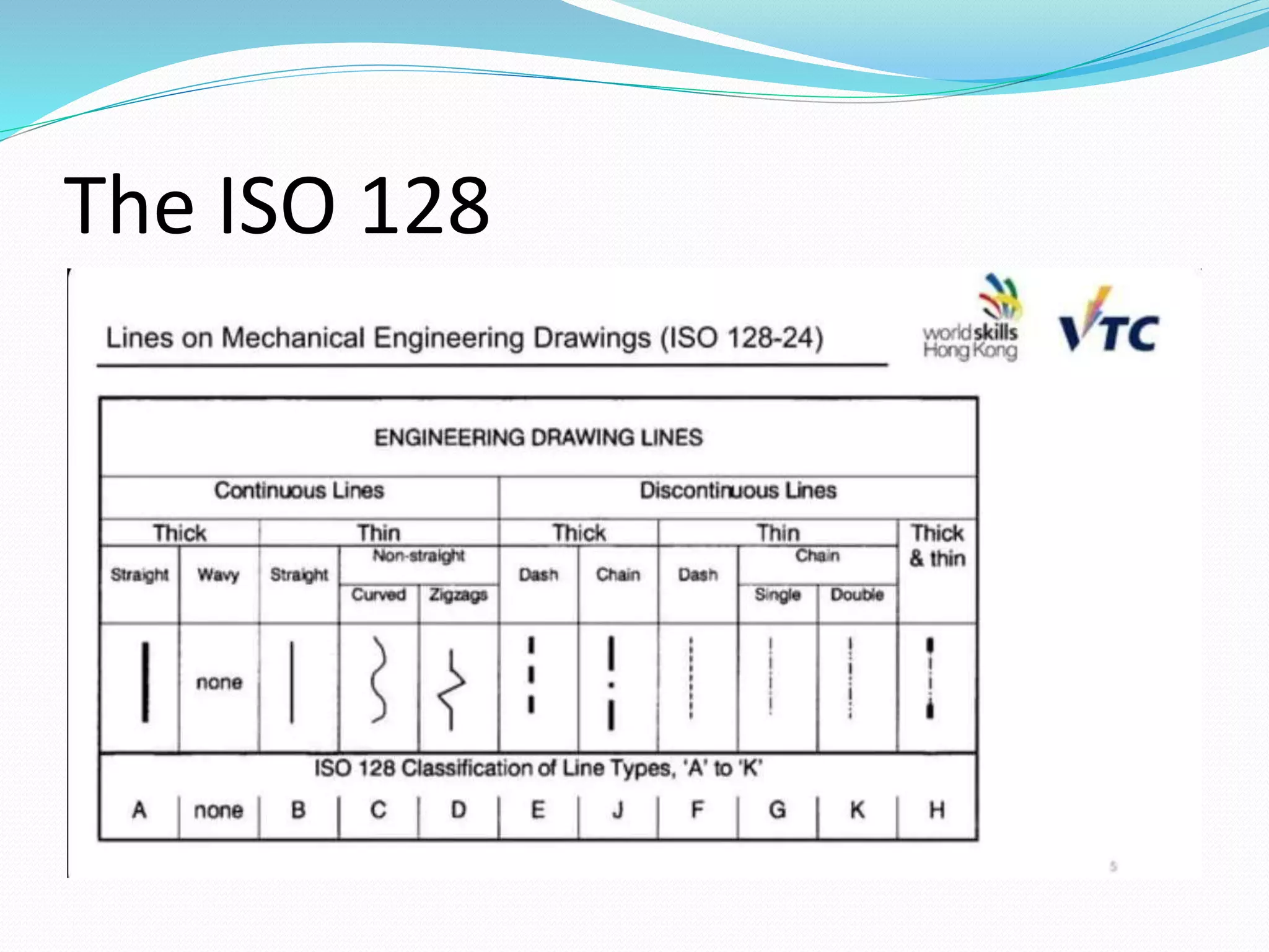
Many of the symbols and principles of technical drawing are
codified in an international standard called ISO 128.
ISO 128 - is an international standard issued by International
Organization for Standard [ISO 128].
• General principles of presentation in technical drawings.
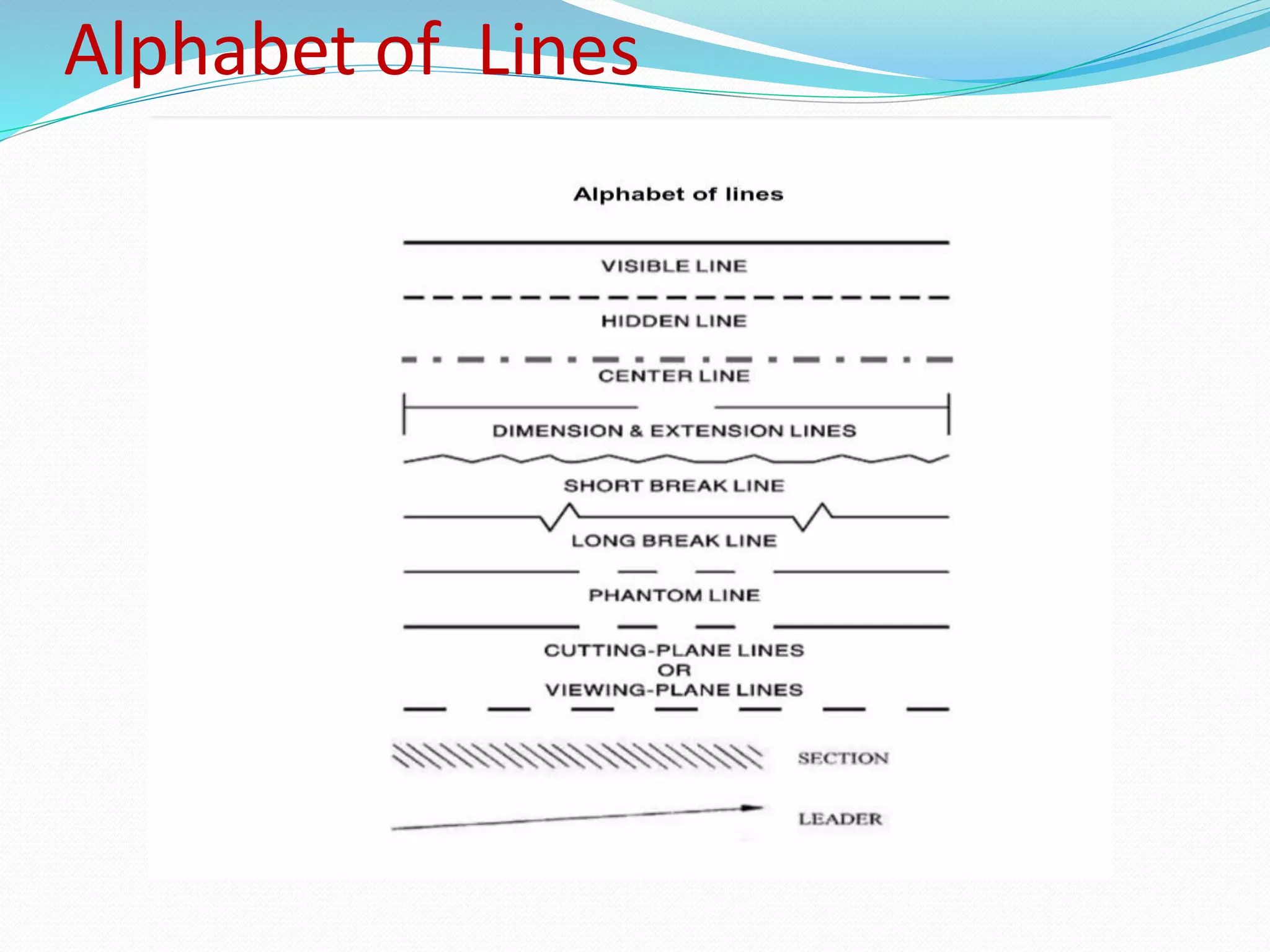
• It describes basic conventions for ; lines, views, cuts and section,
and different types of engineering drawings like;
• Mechanical engineering
• Architecture
• Civil engineering
• and shipbuilding
- It’s applicable to both manual computer-based-drawing](https://image.slidesharecdn.com/interpretdrawingandplanscarpentry-230416174210-1fbb8cad/75/INTERPRET-DRAWING-AND-PLANS-Carpentry-pptx-9-2048.jpg)