ARBAMINCH UNIVERSITY
COLLEGE OFNATURAL SCIENCES
DEPARTMENT OF CHEMISTRY
Process Equipment Design and Drawing
IChem.601
Unit-3
3.1 Introduction to Drawing
1
2.
• Communication isdefined as, “the act of
communicating, that is, passing on news,
information, feelings etc.”
• The purpose of communication – irrespective of the
form/means in which it is conveyed – is to pass a
message from one person or group of people to
another person or group in the most convenient way.
Equipment Design and Drawing
Unit-III
Definition & types of communication
2
3.
• The twomain forms of communication are
through audio and visual means.
• Audio means rely on sound signals that are
perceived by ears. Sound producing/receiving
devices are used for this purpose.
• Visual means on the other hand, depend on light
signals (images) that are perceived by eyes. Image
producing/receiving devices are used for this
purpose. This may include things like text,
drawings, figures, photographs, video images, TV
images, images of real objects etc.
3
4.
Technical Communication:
Technical communicationis an advanced form of
communication whereby people of the same
trade (profession) can convey messages to one
another more accurately and precisely. To
achieve this, a technical language, which is well
standardized, is needed (e.g. object names,
botanical names for plant scientists, etc).
A Drawing is a graphic representation of an object,
or a part of it, and is the result of creative thought
by an engineer or technician.
• One of the most widely used forms of graphic
communication is the drawing.
4
5.
• It isthe graphic language from which a trained
person can visualize objects.
• It is a Universal language of engineers.
• There are two basic types of drawings:
Artistic and Technical drawings.
• Artistic Drawings
• Artistic Drawings range in scope from the simplest
line drawing to the most famous paintings.
Regardless of their complexity, artistic drawings are
used to express the feelings, beliefs, philosophies
and ideas of the artist
5
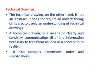
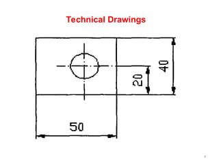
Technical Drawings
• Thetechnical drawing, on the other hand, is not
an abstract. It does not require an understanding
of its creator, only an understanding of technical
drawings.
• A technical drawing is a means of clearly and
concisely communicating all of the information
necessary to transform an idea or a concept in to
reality.
• It also contains dimensions, notes and
specifications.
7
8.
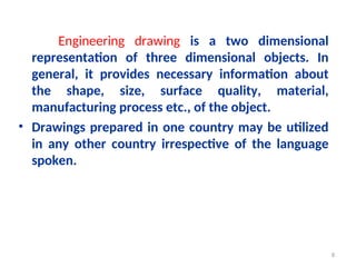
Engineering drawing isa two dimensional
representation of three dimensional objects. In
general, it provides necessary information about
the shape, size, surface quality, material,
manufacturing process etc., of the object.
• Drawings prepared in one country may be utilized
in any other country irrespective of the language
spoken.
8
Role of EngineeringDrawing
• The ability to read drawing is the most important
requirement of all technical people in any
profession.
Applications: Building drawing for civil engineers,
machine drawing for mechanical engineers, circuit
diagrams for electrical and electronics engineers,
Equipment design, drawing for chemical engineers
and computer graphics for one and all.
10
11.
The subject ingeneral is designed to impart the
following skills.
Ability to read and prepare engineering drawings.
Ability to make free - hand sketching of objects.
Power to imagine, analyze and communicate, and
capacity to understand other subjects.
11
12.
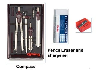
Drawing Instrument andAids
The Instruments and other aids used in drawing
work are listed below:
1. Drawing board 6. Set of scales
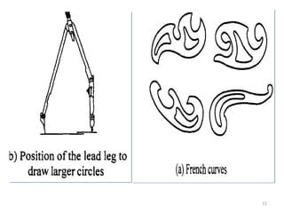
2. Mini drafter 7. French curves
3. Instrument box 8. Drawing sheets
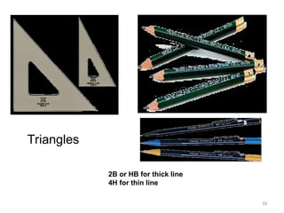
4. Set squares 9. Pencils
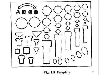
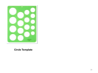
5. Protractor 10. Templates
12
13.
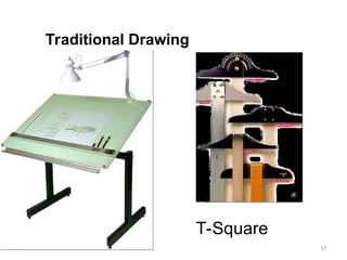
Drawing Board
• Untilrecently drawing boards used are made of well
seasoned softwood of about 25 mm thick with a working
edge.
• Mini-drafters are fixed on any board. The standard size
of board depends on the size of drawing sheet size
required.
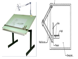
Mini-Drafter
• Mini-drafter consists of an angle formed by two arms
with scales marked and rigidly hinged to each other. It
combines the functions of T-square, set-squares, scales
and protractor. It is used for drawing horizontal, vertical
and inclined lines, parallel and perpendicular lines and
for measuring lines and angles.
13
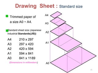
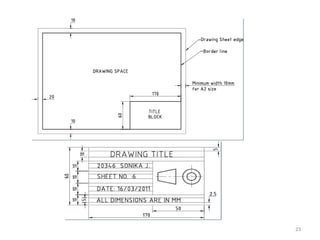
Drawing Sheet :Standard size
Trimmed paper of
a size A0 ~ A4.
Standard sheet size (Japanese
Industrial Standards(JIS))
A4 210 x 297
A3 297 x 420
A2 420 x 594
A1 594 x 841
A0 841 x 1189
A4
A3
A2
A1
A0
(Dimensions in millimeters)
21
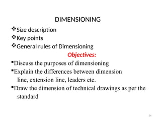
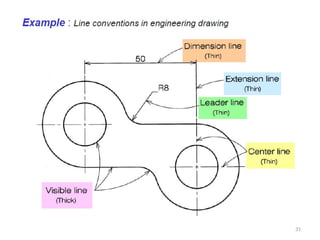
DIMENSIONING
Size description
Key points
Generalrules of Dimensioning
Objectives:
Discuss the purposes of dimensioning
Explain the differences between dimension
line, extension line, leaders etc.
Draw the dimension of technical drawings as per the
standard
24
25.
• What doyou understand from the word
Dimensioning?
• How do you describe the size of your class
room on drawing?
Dimensioning
Size Dimensioning
It is used to describe size of an object such as
height, width, depth, thickness, length,
radius, diameter etc., with regard to its form
and other features like holes and slots.
25
Dimension : Refersto the numerical value used
to give distance information. The dimensions of the
room are 26 feet by 15 feet.
• The shape description is based upon the theory
of projection. The size description is
based upon the theory of dimensioning.
• A dimension is the art by which the dimensions
of an object are written on its drawing.
27
28.
• The purposeof dimensioning is to provide a clear and
complete description of an object. A complete set of
dimensions will permit only one interpretation needed
to construct the part. Dimensioning should follow
these guidelines.
1. Accuracy: correct values must be given.
2. Clearness: dimensions must be placed in appropriate
positions.
3. Completeness: nothing must be left out, and nothing
duplicated.
4. Readability: the appropriate line quality must be used
for legibility.
28
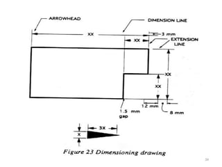
• Dimension line:is a thin line, broken in the middle
to allow the placement of the dimension value, with
arrowheads at each end.
An arrowhead is approximately 3 mm long and 1 mm
wide. That is, the length is roughly three times the
width.
• An extension line extends a line on the object to
the dimension line. The first dimension line should
be approximately 12 mm (0.6 in) from the object.
• Extension lines begin 1.5 mm from the object and
extend 3 mm from the last dimension line.
32
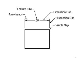
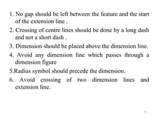
1. No gapshould be left between the feature and the start
of the extension line .
2. Crossing of centre lines should be done by a long dash
and not a short dash .
3. Dimension should be placed above the dimension line.
4. Avoid any dimension line which passes through a
dimension figure
5.Radius symbol should precede the dimension.
6. Avoid crossing of two dimension lines and
extension line.
35
36.
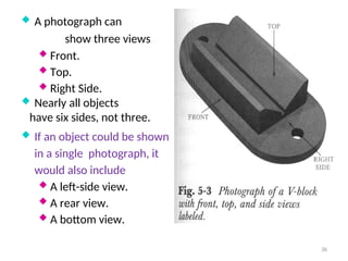
A photographcan
show three views
Front.
Top.
Right Side.
Nearly all objects
have six sides, not three.
If an object could be shown
in a single photograph, it
would also include
A left-side view.
A rear view.
A bottom view.
36
37.
3
7
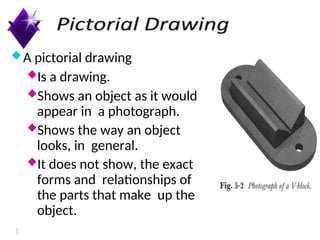
A pictorial drawing
Isa drawing.
Shows an object as it would
appear in a photograph.
Shows the way an object
looks, in general.
It does not show, the exact
forms and relationships of
the parts that make up the
object.
38.
To describeaccurately the shape of each view
imagine a position
Directly in front of the object.
Directly above the object.
On the right side of the object.
The front, top and right side views are the ones
most often used to describe an object in technical
drawing.
They are called the Normal views.
38
39.
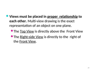
Views mustbe placed in proper relationship to
each other. Multi-view drawing is the exact
representation of an object on one plane.
The Top View is directly above the Front View
The Right-side View is directly to the right of
the Front View.
39
40.
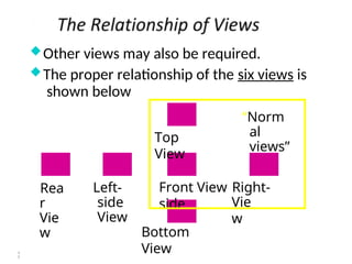
Other views mayalso be required.
The proper relationship of the six views is
shown below
Top
View
Bottom
View
Left-
side
View
Rea
r
Vie
w
Front View Right-
side Vie
w
“Norm
al
views”
4
0