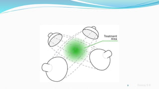
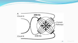
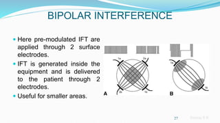
Sreeraj S R
Sreeraj S R
2
Sreeraj S R
DEFINITION
 Developed by Dr. Hans Nemec of Vienna, Austria in the
early 1950’s
 It may be described as the transcutaneous application of
alternating medium frequency electrical currents,
amplitude modulated at low frequency for therapeutic
purposes.
3
Sreeraj S R
Why IFT?..
 MF currents associated with a lower skin resistance (impedance),
 more comfortable than low frequency currents
 more tolerable penetration of current through the skin is possible
4
Sreeraj S R
SKIN IMPEDANCE
 The word impedance comes from the Latin impedire meaning to
prevent, to stop from going on.
 Impedance signifies the resistance of a conductor when an electric
current passes.
 Conventionally speaking, the term resistance refers to the obstacle to
the direct current, and it is represented by the letter R.
 The terms impedance refers to the obstacle to the alternating current
and it is represented by the letter Z.
 Impedance Z, as resistance R, is expressed in ohms.
5
Sreeraj S R
SKIN IMPEDANCE
 SKIN IMPEDANCE is calculated as Z = ½ π f C Where,
 Z = skin resistance
 f = frequency in Hertz (Hz)
 C = capacitance of skin in microfarads
 From above formula, skin impedance is inversely proportional to
frequency and capacitance of the skin.
 Capacitance of the skin cannot be changed; hence by increasing the
frequency the skin impedance can be lowered.
6
Sreeraj S R
SKIN IMPEDANCE
 It is assumed that a capacitance of 1 microfarad (1 μF) i.e. equivalent
to 0.000001 (10 to the -6th power).
 For a 50-Hz alternating current we obtain:
Z = 1/2π x 50x 10-6 = 3200 Ω
 For a 4,000-Hz alternating current this means:
Z = 1/2π x 4000x 10-6 = 39.8 Ω
7
Sreeraj S R
PRINCIPLE
 The principle of IFT is to pass two Medium Frequency
Alternating Currents which are slightly out of phase,
through the tissues, where the currents intersect to
produce a low frequency effect.
8
Sreeraj S R
9
Sreeraj S R
Principles of wave interference: Combined Effects
 Constructive, Destructive, & Continuous
 Constructive interference: when two sinusoidal waves that are exactly
in phase or one, two or three wavelengths out of phase, the waves
supplement each other in constructive interference
10
+ =
Sreeraj S R
Principles of wave interference: Combined
Effects
 Destructive interference: when the two waves are different by 1/2 a
wavelength (of any multiple) the result is cancellation of both waves.
+ =
11
Sreeraj S R
Principles of wave interference: Combined
Effects
 Continuous Interference: Two waves slightly out of phase collide and
form a single wave with progressively increasing and decreasing
amplitude
=
+
12
Sreeraj S R
WORKING
 In the interferential therapy method, two medium-frequency alternating
currents that interact with each other are used.
 One of the alternating currents has a fixed frequency of 4,000 Hz while
the frequency of the other alternating current can be set between 4,000
to 4,250 Hz.
 The superimposition of one alternating current on the other is called
interference
13
Sreeraj S R
Carrying Frequency
 The frequency of the new medium-frequency alternating current can be
calculated as follows:
 f1 + f2 /2 where
 Example:
f1 = 4,000 Hz
f2 = 4,150Hz
Resultant Carrying Frequency = 4,000 + 4,150/2 = 4,075 Hz
14
Sreeraj S R
Beat Frequency
 The frequency with which the amplitude varies is referred to as the
Beat Frequency.
 In interferential therapy the AMF (treatment frequency) corresponds to
frequencies which are used in low-frequency electrotherapy.
15
Sreeraj S R
Beat Frequency
 The AMF has a value of f2 - f1
 Example:
f1 = 4,000 Hz
f2 = 4,150 Hz
f 2 - f 1 = 4,150 - 4,000 = 150 Hz (AMF or treatment frequency)
16
Sreeraj S R
Beat Frequency
17
4000 Hz
4150 Hz
150 Hz
Sreeraj S R
18
4000 Hz
4100 Hz
Sreeraj S R
Why Amplitude modulation?
 Synchronous depolarization
 Asynchronous depolarization
 Gildemeister effect/summation principle
 Wedensky inhibition
19
Sreeraj S R
SWEEP
 The principle of using the sweep is that the machine is set to
automatically vary the effective stimulation frequency using either pre-
set or user set sweep ranges.
 Such sweep prevents accommodation of nerves.
Example:
 An AMF of 20 Hz is set and a 50 Hz spectrum is added.
 The current begins with an AMF of 20 Hz and passes successively
through all frequencies up to 70 Hz, after which it decreases gradually
to 20 Hz.
 This process is repeated automatically.
20
Sreeraj S R
Triangular sweep pattern Rectangular Sweep Pattern
Trapezoidal Sweep Pattern 21
Sreeraj S R
Amplitude modulation
22
Sreeraj S R
APPLICATION
 Methods of applications are:
1. Static interference
2. Dynamic interference
3. Bipolar interference
23
Sreeraj S R
STATIC INTERFERENCE
 Here the area in which IFT
is set up remains
stationary.
 This area of static
interference gives an
appearance of ‘clover leaf
’.
 It lies to 45°angles to the
perpendicular lines from
each electrode. 24
Sreeraj S R
DYNAMIC INTERFERENCE
 This is moving the area of
interference current in a to and
fro manner through 45°.
 It is obtained by varying the
current intensity from 50 to
100%.
 The dynamic area of
interference is also called as
vector sweep, vector scan,
rotating vector, etc.
25
Sreeraj S R
Vector Scan
26
Sreeraj S R
BIPOLAR INTERFERENCE
 Here pre-modulated IFT are
applied through 2 surface
electrodes.
 IFT is generated inside the
equipment and is delivered
to the patient through 2
electrodes.
 Useful for smaller areas.
27
Sreeraj S R
INSTRUMENTATION
 AMF PARAMETER To choose the basic value of the LF modulation that is
desired.
 SPECTRUM/ SWEEP PARAMETER to set the range of variation in the AMF
value that is desired; for ex. AMF at 100Hz and spectrum at 50Hz will give an
AMF variation from 100hz up to 150Hz and back to 100Hz.
 ROTATION PARAMETER is applicable in case of vector currents only and
sets the rate of rotation and the direction change of the AMF field within the
tissues.
28
Sreeraj S R
PHYSIOLOGICAL EFFECTS
 This depends upon:
1. Magnitude of current
2. Type of mode used i.e. Rhythmic or constant
3. The frequency range used
4. Accuracy of electrode positioning
29
Sreeraj S R
PHYSIO.EFFECTS (CONT…)
Main clinical applications are :
1. Pain relief
2. Muscle stimulation
3. Increased local blood flow
4. Reduction of edema
30
Sreeraj S R
PAIN RELIEF
 Higher frequencies of 90 - 130 Hz to stimulate the pain gate
mechanisms & thereby mask the pain symptoms.
 Lower frequencies of 2 – 5 Hz can be used to activate the opioid
mechanisms
31
Sreeraj S R
MUSCLE STIMULATION
 For patients who can not generate useful voluntary
contraction, IFT may be beneficial.
 Stimulation at low frequency, for e.g. 1 Hz will result in a
series of twitches
 Stimulation at 50 Hz will result in a tetanic contraction.
 Most effective motor nerve stimulation range is between
10 - 25 Hz.
32
Sreeraj S R
BLOOD FLOW
 Experimentation demonstrated vascular changes at 10 -
25Hz.
 Effects of blood flow is believed to be due to:
1. Effects of suction electrodes on tissues
2. Effects of muscle stimulation on circulation.
3. Possibility that the IFT is acting as an inhibitor for
sympathetic activity. (Sympathetic nervous system stimulation
causes vasoconstriction of most blood vessels.)
33
Sreeraj S R
OEDEMA
 A rhythmical pumping action at a frequency of 1-10 Hz
 The effects are associated with the effects on Muscle
Stimulation & Blood Flow.
34
Sreeraj S R
CONTRAINDICATIONS
1. Cardiac pacemaker
2. Advanced cardiac disease
3. Hypertension
4. Thrombosis
5. Hemorrhage
6. Pregnancy
7. Neoplasm
8. T B
9. Fever
10. Infections
11. The eyes
12. Skin disorders
13. Epiphyseal region in children
35
Sreeraj S R
PRECAUTIONS
 IFT apparatus must be at least 6 meters away from SWD
machine
 Patients with febrile conditions
 Epileptic patients
 Over anterior chest wall
 Position suction electrode below the level of damage or
discomfort.
36
Sreeraj S R
Placement of electrodes
37
Sreeraj S R
Types of Electrodes
 Plate
 Vacuum
 Pen
38
Sreeraj S R
Plate Electrodes
 Made of conducting rubber
which are comfortable and
long lasting
 larger plates electrodes give
more comfortable treatment
and deeper effect
 Smaller electrodes are used
for a localized effect, but this
effect is more superficial
 Attached to the patient by
means of straps to assure a
good contact and greater
tolerance of treatment
Sreeraj S R
Sreeraj S R
Vacuum Electrodes
 Excellent for treating flat
smooth areas for example
back or a plump knee
 Not indicated for treatment of
the hairy areas because can’t
get an airtight seal
Sreeraj S R
Sreeraj S R
Electrode positioning
43
Sreeraj S R
ELBOW
44
Sreeraj S R
KNEE
45
Sreeraj S R
NECK
46
Sreeraj S R
SHOULDER
47
Sreeraj S R
LOWER BACK
48
Sreeraj S R
49
Sreeraj S R
Overview
 These are medium frequency alternating current in the low kHz
range, which is delivered in a pulsed (or burst or interrupted)
output.
 The pulsing or bursting is at a 'low' frequency, and as a result,
nerves will respond.
 It is primarily employed to generating a motor response.
 Burst Mode Alternating Current (BMAC).
 The credit for the early work in this field is ascribed to Dr Yakov Kots,
based in Russia, in the late 1970s.
50
Sreeraj S R
 The term 'Russian currents' refers to sinusoidal AC of frequency
2.5 kHz which is burst-modulated at 50 Hz.
 It consists of 10 ms bursts of AC separated by 10 ms 'off' periods.
The waveform repeats every 20 ms (1/50th sec) so the burst or
modulation frequency is 50 Hz.
51
Sreeraj S R
Characteristics
 Carrier Frequency: 2500Hz.
 Waveform: Polyphasic sinusoidal
waveform.
 Bursts Frequency: 50 Hz.
 Burst Duration: 10 ms
 Interburst interval: 10 ms
 Phase Duration: 0.2 ms
 Current Amplitude: The
maximum current amplitude is
100mA. Clinical used at 70mA.
52
2.5 kHz sinusoidal AC, burst modulated
at 50 Hz i.e. 10 ms 'on' and 10 ms 'off'.
Sreeraj S R
Dosing Parameters
 Base Frequency : 2500Hz (2.5kHz)
 Burst @ 50Hz
 10 ms ON : 10 ms OFF (50% duty cycle)
 Stimulation delivered thus for 10 seconds
 Rest period of 50 seconds
 Repeated 10 minutes per session
 Maximum tolerable intensity
 Applied once daily over a period of weeks
53
Sreeraj S R
54
Thank You

interferentialtherapysrs-200404152722.pdf

  • 1.
  • 2.
  • 3.
    Sreeraj S R DEFINITION Developed by Dr. Hans Nemec of Vienna, Austria in the early 1950’s  It may be described as the transcutaneous application of alternating medium frequency electrical currents, amplitude modulated at low frequency for therapeutic purposes. 3
  • 4.
    Sreeraj S R WhyIFT?..  MF currents associated with a lower skin resistance (impedance),  more comfortable than low frequency currents  more tolerable penetration of current through the skin is possible 4
  • 5.
    Sreeraj S R SKINIMPEDANCE  The word impedance comes from the Latin impedire meaning to prevent, to stop from going on.  Impedance signifies the resistance of a conductor when an electric current passes.  Conventionally speaking, the term resistance refers to the obstacle to the direct current, and it is represented by the letter R.  The terms impedance refers to the obstacle to the alternating current and it is represented by the letter Z.  Impedance Z, as resistance R, is expressed in ohms. 5
  • 6.
    Sreeraj S R SKINIMPEDANCE  SKIN IMPEDANCE is calculated as Z = ½ π f C Where,  Z = skin resistance  f = frequency in Hertz (Hz)  C = capacitance of skin in microfarads  From above formula, skin impedance is inversely proportional to frequency and capacitance of the skin.  Capacitance of the skin cannot be changed; hence by increasing the frequency the skin impedance can be lowered. 6
  • 7.
    Sreeraj S R SKINIMPEDANCE  It is assumed that a capacitance of 1 microfarad (1 μF) i.e. equivalent to 0.000001 (10 to the -6th power).  For a 50-Hz alternating current we obtain: Z = 1/2π x 50x 10-6 = 3200 Ω  For a 4,000-Hz alternating current this means: Z = 1/2π x 4000x 10-6 = 39.8 Ω 7
  • 8.
    Sreeraj S R PRINCIPLE The principle of IFT is to pass two Medium Frequency Alternating Currents which are slightly out of phase, through the tissues, where the currents intersect to produce a low frequency effect. 8
  • 9.
  • 10.
    Sreeraj S R Principlesof wave interference: Combined Effects  Constructive, Destructive, & Continuous  Constructive interference: when two sinusoidal waves that are exactly in phase or one, two or three wavelengths out of phase, the waves supplement each other in constructive interference 10 + =
  • 11.
    Sreeraj S R Principlesof wave interference: Combined Effects  Destructive interference: when the two waves are different by 1/2 a wavelength (of any multiple) the result is cancellation of both waves. + = 11
  • 12.
    Sreeraj S R Principlesof wave interference: Combined Effects  Continuous Interference: Two waves slightly out of phase collide and form a single wave with progressively increasing and decreasing amplitude = + 12
  • 13.
    Sreeraj S R WORKING In the interferential therapy method, two medium-frequency alternating currents that interact with each other are used.  One of the alternating currents has a fixed frequency of 4,000 Hz while the frequency of the other alternating current can be set between 4,000 to 4,250 Hz.  The superimposition of one alternating current on the other is called interference 13
  • 14.
    Sreeraj S R CarryingFrequency  The frequency of the new medium-frequency alternating current can be calculated as follows:  f1 + f2 /2 where  Example: f1 = 4,000 Hz f2 = 4,150Hz Resultant Carrying Frequency = 4,000 + 4,150/2 = 4,075 Hz 14
  • 15.
    Sreeraj S R BeatFrequency  The frequency with which the amplitude varies is referred to as the Beat Frequency.  In interferential therapy the AMF (treatment frequency) corresponds to frequencies which are used in low-frequency electrotherapy. 15
  • 16.
    Sreeraj S R BeatFrequency  The AMF has a value of f2 - f1  Example: f1 = 4,000 Hz f2 = 4,150 Hz f 2 - f 1 = 4,150 - 4,000 = 150 Hz (AMF or treatment frequency) 16
  • 17.
    Sreeraj S R BeatFrequency 17 4000 Hz 4150 Hz 150 Hz
  • 18.
  • 19.
    Sreeraj S R WhyAmplitude modulation?  Synchronous depolarization  Asynchronous depolarization  Gildemeister effect/summation principle  Wedensky inhibition 19
  • 20.
    Sreeraj S R SWEEP The principle of using the sweep is that the machine is set to automatically vary the effective stimulation frequency using either pre- set or user set sweep ranges.  Such sweep prevents accommodation of nerves. Example:  An AMF of 20 Hz is set and a 50 Hz spectrum is added.  The current begins with an AMF of 20 Hz and passes successively through all frequencies up to 70 Hz, after which it decreases gradually to 20 Hz.  This process is repeated automatically. 20
  • 21.
    Sreeraj S R Triangularsweep pattern Rectangular Sweep Pattern Trapezoidal Sweep Pattern 21
  • 22.
    Sreeraj S R Amplitudemodulation 22
  • 23.
    Sreeraj S R APPLICATION Methods of applications are: 1. Static interference 2. Dynamic interference 3. Bipolar interference 23
  • 24.
    Sreeraj S R STATICINTERFERENCE  Here the area in which IFT is set up remains stationary.  This area of static interference gives an appearance of ‘clover leaf ’.  It lies to 45°angles to the perpendicular lines from each electrode. 24
  • 25.
    Sreeraj S R DYNAMICINTERFERENCE  This is moving the area of interference current in a to and fro manner through 45°.  It is obtained by varying the current intensity from 50 to 100%.  The dynamic area of interference is also called as vector sweep, vector scan, rotating vector, etc. 25
  • 26.
  • 27.
    Sreeraj S R BIPOLARINTERFERENCE  Here pre-modulated IFT are applied through 2 surface electrodes.  IFT is generated inside the equipment and is delivered to the patient through 2 electrodes.  Useful for smaller areas. 27
  • 28.
    Sreeraj S R INSTRUMENTATION AMF PARAMETER To choose the basic value of the LF modulation that is desired.  SPECTRUM/ SWEEP PARAMETER to set the range of variation in the AMF value that is desired; for ex. AMF at 100Hz and spectrum at 50Hz will give an AMF variation from 100hz up to 150Hz and back to 100Hz.  ROTATION PARAMETER is applicable in case of vector currents only and sets the rate of rotation and the direction change of the AMF field within the tissues. 28
  • 29.
    Sreeraj S R PHYSIOLOGICALEFFECTS  This depends upon: 1. Magnitude of current 2. Type of mode used i.e. Rhythmic or constant 3. The frequency range used 4. Accuracy of electrode positioning 29
  • 30.
    Sreeraj S R PHYSIO.EFFECTS(CONT…) Main clinical applications are : 1. Pain relief 2. Muscle stimulation 3. Increased local blood flow 4. Reduction of edema 30
  • 31.
    Sreeraj S R PAINRELIEF  Higher frequencies of 90 - 130 Hz to stimulate the pain gate mechanisms & thereby mask the pain symptoms.  Lower frequencies of 2 – 5 Hz can be used to activate the opioid mechanisms 31
  • 32.
    Sreeraj S R MUSCLESTIMULATION  For patients who can not generate useful voluntary contraction, IFT may be beneficial.  Stimulation at low frequency, for e.g. 1 Hz will result in a series of twitches  Stimulation at 50 Hz will result in a tetanic contraction.  Most effective motor nerve stimulation range is between 10 - 25 Hz. 32
  • 33.
    Sreeraj S R BLOODFLOW  Experimentation demonstrated vascular changes at 10 - 25Hz.  Effects of blood flow is believed to be due to: 1. Effects of suction electrodes on tissues 2. Effects of muscle stimulation on circulation. 3. Possibility that the IFT is acting as an inhibitor for sympathetic activity. (Sympathetic nervous system stimulation causes vasoconstriction of most blood vessels.) 33
  • 34.
    Sreeraj S R OEDEMA A rhythmical pumping action at a frequency of 1-10 Hz  The effects are associated with the effects on Muscle Stimulation & Blood Flow. 34
  • 35.
    Sreeraj S R CONTRAINDICATIONS 1.Cardiac pacemaker 2. Advanced cardiac disease 3. Hypertension 4. Thrombosis 5. Hemorrhage 6. Pregnancy 7. Neoplasm 8. T B 9. Fever 10. Infections 11. The eyes 12. Skin disorders 13. Epiphyseal region in children 35
  • 36.
    Sreeraj S R PRECAUTIONS IFT apparatus must be at least 6 meters away from SWD machine  Patients with febrile conditions  Epileptic patients  Over anterior chest wall  Position suction electrode below the level of damage or discomfort. 36
  • 37.
    Sreeraj S R Placementof electrodes 37
  • 38.
    Sreeraj S R Typesof Electrodes  Plate  Vacuum  Pen 38
  • 39.
    Sreeraj S R PlateElectrodes  Made of conducting rubber which are comfortable and long lasting  larger plates electrodes give more comfortable treatment and deeper effect  Smaller electrodes are used for a localized effect, but this effect is more superficial  Attached to the patient by means of straps to assure a good contact and greater tolerance of treatment
  • 40.
  • 41.
    Sreeraj S R VacuumElectrodes  Excellent for treating flat smooth areas for example back or a plump knee  Not indicated for treatment of the hairy areas because can’t get an airtight seal
  • 42.
  • 43.
    Sreeraj S R Electrodepositioning 43
  • 44.
  • 45.
  • 46.
  • 47.
  • 48.
  • 49.
  • 50.
    Sreeraj S R Overview These are medium frequency alternating current in the low kHz range, which is delivered in a pulsed (or burst or interrupted) output.  The pulsing or bursting is at a 'low' frequency, and as a result, nerves will respond.  It is primarily employed to generating a motor response.  Burst Mode Alternating Current (BMAC).  The credit for the early work in this field is ascribed to Dr Yakov Kots, based in Russia, in the late 1970s. 50
  • 51.
    Sreeraj S R The term 'Russian currents' refers to sinusoidal AC of frequency 2.5 kHz which is burst-modulated at 50 Hz.  It consists of 10 ms bursts of AC separated by 10 ms 'off' periods. The waveform repeats every 20 ms (1/50th sec) so the burst or modulation frequency is 50 Hz. 51
  • 52.
    Sreeraj S R Characteristics Carrier Frequency: 2500Hz.  Waveform: Polyphasic sinusoidal waveform.  Bursts Frequency: 50 Hz.  Burst Duration: 10 ms  Interburst interval: 10 ms  Phase Duration: 0.2 ms  Current Amplitude: The maximum current amplitude is 100mA. Clinical used at 70mA. 52 2.5 kHz sinusoidal AC, burst modulated at 50 Hz i.e. 10 ms 'on' and 10 ms 'off'.
  • 53.
    Sreeraj S R DosingParameters  Base Frequency : 2500Hz (2.5kHz)  Burst @ 50Hz  10 ms ON : 10 ms OFF (50% duty cycle)  Stimulation delivered thus for 10 seconds  Rest period of 50 seconds  Repeated 10 minutes per session  Maximum tolerable intensity  Applied once daily over a period of weeks 53
  • 54.