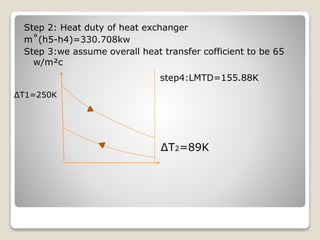
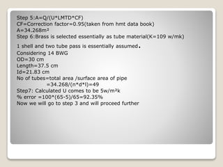
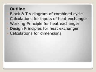
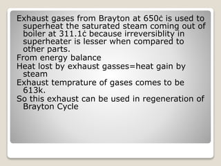
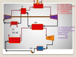
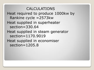
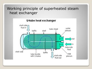
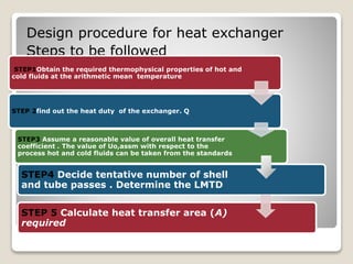
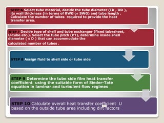
the ladakh protest in leh ladakh 2024 sonam wangchuk.pptx
integrated brayton and rankine cycle
1. A Presentation on integration
of Rankine and Brayton Cycle
Presented by:
Manish Kumar Jaiswal
Upendra Yadav
Vikas Upadhyay
Pushpendra Mishra
Vamshi Kanuganti
Amit srivastave
Instructor :Dr Laltu Chandra
2. Outline
• Block & T-s diagram of combined cycle
• Calculations for inputs of heat exchanger
• Working Principle for heat exchanger
• Design Principles for heat exchanger
• Calculations for dimensions
3. Exhaust gases from Brayton at 650ċ is used to
superheat the saturated steam coming out of
boiler at 311.1ċ because irreversiblity in
superheater is lesser when compared to
other parts.
From energy balance
Heat lost by exhaust gasses=heat gain by
steam
Exhaust temprature of gases comes to be
613k.
So this exhaust can be used in regeneration of
Brayton Cycle
4. T1
C
SG &E
T2
CDCP
HI =HEAT INPUT
T1= BRAYTON TURBINE
SH=SUPER HEATER
RG=REGENERATOR
C= COMPERSOR
IC= INTER COOLER
T2=RANKINE TURBINE
CD=CONDENSOR
CP=CONDESATE PUMP
SG&E=STEAM
GENERATOR
AND
ECONOMISER
HI
R
G
SH
IC
5. T
3 4
T2=47.89ᴼC
1 6
5
f
eg
h
a
b c i
d
a-b=isentropic compression
a-c=non isentropic compression
c-i=heat recovered in regeneration
i-d=heat added in heat exchanger
d-e= isentropic expansion
d-f= non isentropic expansion
f-g= heat transfer to saturated
steam in super heater
g-h= heat transfer from hot fluid in
regenerator
h-a=heat rejected to inter cooler
1-2= isentropic pump
2-3= heat added in
economizer
3-4= heat added in steam
generator
4-5= heat added in super
heat exchanger
5-6= turbine expansion
6-1= isobaric heat rejection
7. Parameter Value
Compressor Type Radial Centrifugal Compressor
Pressure Ratio 4.8:1 (Optimum)
Compressor Inlet Temp. 339K
Compressor Outlet Temp. 578.6K
Isentropic efficiency of Compressor 80% (assumed)
Fuel type Natural Gas
Calorific Value 12,500Kcal/kg
Turbine Type Radial Turbine (ABB MT100)
Turbine Inlet Temp. 1223K
Turbine Outlet Temp. 923K
Isentropic efficiency Of Turbine 85% (Assumed)
Brayton Cycle Design Parameter
8. CALCULATIONS
Heat required to produce 1000kw by
Rankine cycle =2573kw
Heat supplied in superheater
section=330.64
Heat supplied in steam generator
section=1170.9019
Heat supplied in economiser
section=1205.8
10. Design procedure for heat exchanger
Steps to be followed
STEP 5 Calculate heat transfer area (A)
required
STEP4 Decide tentative number of shell
and tube passes . Determine the LMTD
STEP1Obtain the required thermophysical properties of hot and
cold fluids at the arithmetic mean temperature
STEP 2find out the heat duty of the exchanger. Q
STEP3 Assume a reasonable value of overall heat transfer
coefficient . The value of Uo,assm with respect to the
process hot and cold fluids can be taken from the standards
11. STEP 7 Decide type of shell and tube exchanger (fixed tubesheet,
U-tube etc.). Select the tube pitch (PT), determine inside shell
diameter ( s D ) that can accommodate the
calculated number of tubes .
STEP 8 Assign fluid to shell side or tube side
STEP 9 Determine the tube side film heat transfer
coefficient using the suitable form of Sieder-Tate
equation in laminar and turbulent flow regimes
STEP 10 Calculate overall heat transfer coefficient U
based on the outside tube area including dirt factors
STEP 6 Select tube material, decide the tube diameter (ID , OD ),
its wall thickness (in terms of BWG or SWG) and tube length .
Calculate the number of tubes required to provide the heat
transfer area.
12. IF calculated
error is less than
30 %
Y
E
S
N
O
Yes then go to next
step 11
Then go back to step 5
and re calculate the area
using calculated U
13. STEP 11 Calculate % overdesign. Overdesign represents extra
surface area provided beyond that required to compensate for
fouling. Typical value of 10% or less is acceptable.
14. Design Calculations:
Mean Temprature of hot fluid=556.80ċ
Mean Temprature of cold fluid=355.55ċ
Thermophysical Property at mean
temprature
Property Hot (Air T=550Ċ ) Cold fluid (Steam
p=100b;t=355Ċ)
Viscosity 2.849*e-5 [pa s] 2.23 887791*e-5[Pa
s]
Thermal conductivity 4.357 *e-5[KW/m K] 0.067790711[W/m K]
Constant Pressure
Specific heat
1.0398[kJ/kg K] 3.862395 [kJ/kg K]
Density 0.6418[kg / m3] 43.6832023 [kg/m3]
15. Step 2: Heat duty of heat exchanger
m˚(h5-h4)=330.708kw
Step 3:we assume overall heat transfer cofficient to be 65
w/m²c
step4:LMTD=155.88K
∆T2=89K
∆T1=250K
16. Step 5:A=Q/(U*LMTD*CF)
CF=Correction factor=0.95(taken from hmt data book)
A=34.268m²
Step 6:Brass is selected essentially as tube material(K=109 w/mk)
1 shell and two tube pass is essentially assumed.
Considering 14 BWG
OD=30 cm
Length=37.5 cm
Id=21.83 cm
No of tubes=total area /surface area of pipe
=34.268/(π*d*l)=49
Step7: Calculated U comes to be 5w/m²k
% error =100*(65-5)/65=92.35%
Now we will go to step 3 and will proceed further