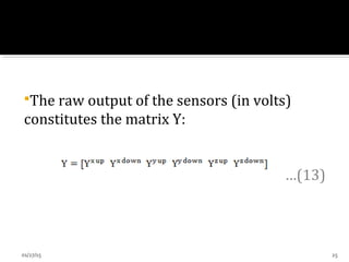
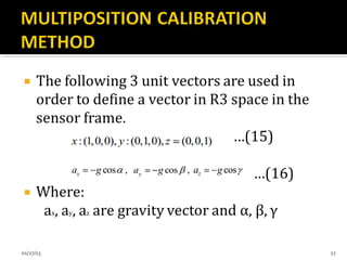
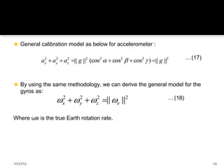
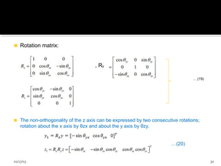
Downloaded 335 times
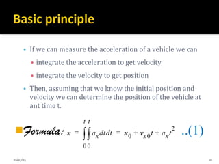
![Figure 1: The body and global frames of reference[10].
01/27/15 7](https://image.slidesharecdn.com/inertialnavigatonsystems11-150127051701-conversion-gate02/85/Inertial-navigaton-systems11-7-320.jpg)
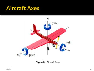
![Figure 2: Inertial measurement unit [12].
01/27/15 9](https://image.slidesharecdn.com/inertialnavigatonsystems11-150127051701-conversion-gate02/85/Inertial-navigaton-systems11-9-320.jpg)
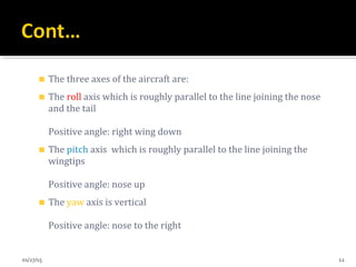
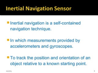
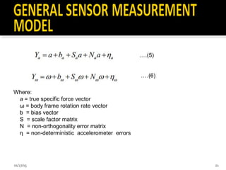
![ In this way
X α A ………(4)
Figure 4: basic sturcture of accelerometer [8]
01/27/15 14](https://image.slidesharecdn.com/inertialnavigatonsystems11-150127051701-conversion-gate02/85/Inertial-navigaton-systems11-14-320.jpg)
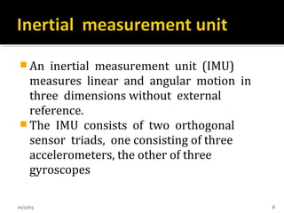
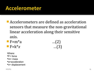
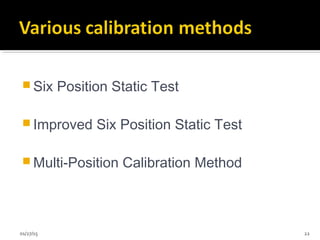
![ Uses Coriolis effect using vibrating elements
▪ Fc -Force m -mass w -angular velocity v –velocity
Figure 7: Coriolis effect [10]
01/27/15 17](https://image.slidesharecdn.com/inertialnavigatonsystems11-150127051701-conversion-gate02/85/Inertial-navigaton-systems11-17-320.jpg)
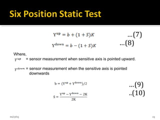
![Figure 9: Relationship between the output voltage of the
accelerometer(gyro) and the measured force(angular rate) [10].
01/27/15 20](https://image.slidesharecdn.com/inertialnavigatonsystems11-150127051701-conversion-gate02/85/Inertial-navigaton-systems11-20-320.jpg)
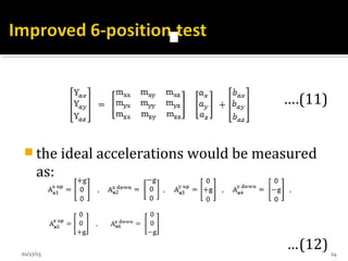

![Figure 10: Misalignment to n-frame [23].
01/27/15 28](https://image.slidesharecdn.com/inertialnavigatonsystems11-150127051701-conversion-gate02/85/Inertial-navigaton-systems11-28-320.jpg)
![ [1] M. Li, A.I. Mourikis, ''3-D Motion Estimation and Online Temporal Calibration for
Camera-IMU Systems,'' Proceedings of the IEEE International Conference on Robotics
and Automation (ICRA), Karlsruhe, Germany, May 2013.
[2] M. Li, B. Kim, A.I. Mourikis, ''Real-time Motion Tracking on a Cellphone using Inertial
Sensing and a Rolling Shutter Camera,'' Proceedings of the IEEE International Conference
on Robotics and Automation (ICRA), Karlsruhe, Germany, May 2013.
[3] M. Li, A.I. Mourikis, ''Optimization-Based Estimator Design for Vision-Aided Inertial
Navigation,'' Proceedings of the Robotics: Science and Systems Conference (RSS),
Sydney, Australia, July 2012.
[4] M. Li, A.I. Mourikis, ''High-Precision, Consistent EKF-based Visual-Inertial Odometry,''
International Journal of Robotics Research (IJRR), Volume 32, No 6, May 2013.
[5] M. Li, A.I. Mourikis, ''Vision-aided Inertial Navigation with Rolling-Shutter Cameras,''
International Journal of Robotics Research (IJRR).
01/27/15 43](https://image.slidesharecdn.com/inertialnavigatonsystems11-150127051701-conversion-gate02/85/Inertial-navigaton-systems11-43-320.jpg)
![ [6] S. Thomas, The Last Navigator: "A Young Man, An Ancient Mariner, the Secrets of the
Sea", McGraw-Hill, New York, 1997.
[7] Adem G. Hayal, "Static Calibration of Tactical Grade Inertial Measurement Units",
Geodetic Science Report No. 496, The Ohio State University Columbus, Ohio 43210, Sep
2008.
[8] Priyanka Aggarwal, Zainab Syed, Aboelmagd Noureldin, Naser El-Sheimy, "MEMS
Based Integrated Navigation", GNSS Technology and Application Series, ISBN-13:
978-1-60807-043-5, 2010.
[9] Hofmann-Wellenhof, B., Lichtenegger, H., and Collins, J., "GPS Theory and Practice",
Fifth Edition, Austria: Springer, 2004.
[10] Grewal, M.S., Weill, L., and Andrews, A.P., "Global Positioning Systems, Inertial
Navigation, and Integration", Second Edition, New Jersey: John Wiley & Sons, 2007.
01/27/15 44](https://image.slidesharecdn.com/inertialnavigatonsystems11-150127051701-conversion-gate02/85/Inertial-navigaton-systems11-44-320.jpg)
![ [11] CLAUDIA C. MERUANE NARANJO, "Analysis and Modeling of MEMS based
Inertial Sensors", Signal Processing, School of Electrical Engineering, XR-EE-SB
2008:011, Stockholm 2008.
[12] Lotters J C, Schipper J, Veltink P H, Olthuis W and Bergveld P, "Procedure for in-use
calibration of triaxial accelerometers in medical application", Sensors Actuators
A68221–8, 1998.
[13] N. El-Sheimy, S. Nassar and A. Noureldin, "Wavelet De-Noising for IMUAlignment",
IEEE Aerospace and Electronics Systems Magazine, vol. 19, pp. 32- 39, Oct. 2004.
[14] Aggarwal, P., et al., "A Standard Testing and Calibration Procedure for Low Cost
MEMS Inertial Sensors and Units", Journal of Navigation, Vol. 61, No. 2, 2007, pp. 323–
336.
[15] Hou, H., and El-Sheimy, N., "Inertial Sensors Errors Modeling Using Allan Variance,"
Proceedings of ION GNSS 2003, Portland, Oregon, Sept. 9–12, 2003.
[16] Hide, C.D., Integration of GPS and Low Cost INS Measurements, Ph.D. thesis, Institute
of Engineering, Surveying and Space Geodesy, University of Nottingham, U.K., 2003.
01/27/15 45](https://image.slidesharecdn.com/inertialnavigatonsystems11-150127051701-conversion-gate02/85/Inertial-navigaton-systems11-45-320.jpg)
![ [17] CLAUDIA C. MERUANE NARANJO, "Analysis and Modeling of MEMS based
Inertial Sensors", Signal Processing, School of Electrical Engineering, XR-EE-SB
2008:011, Stockholm 2008.
[18] El-Sheimy N, " Inertial Techniques and INS/DGPS Integration", Dept. of Geomatics
Enggineering., University of Calgary, Calgary, Canada, 2003.
[19] Ren Wei Zhang Tao, Zhang Hai-yun, Wang Lei-gang, Zhaou Yong-jie, Luan
Mengkai, Liu Hui-feng, Shi Jing-wei,"A Research on Calibration of Low-Precision MEMS
Inertial Sensors", 25th Chinese Control and Decision Conference (CCDC), 2013.
[20] P. Aggarwal, Z. Syed, X. Niu, and N. El-Sheimy, "A standard testing and calibration
procedure for low cost MEMS inertial sensors and units," Journal of navigation, vol. 61, pp.
323-336, 2008.
[21] Titterton, D. H. and Weston, J. L. (1997). "Strapdown Inertial Navigation
Technology". Peter Peregrinus Ltd, UK.
01/27/15 46](https://image.slidesharecdn.com/inertialnavigatonsystems11-150127051701-conversion-gate02/85/Inertial-navigaton-systems11-46-320.jpg)
![ [22] Niu X, “Micromachined Attitude Measurement Unit with Application in Satellite TV Antenna
Stabilization”, PhD Dissertation, Department of Precision Instruments and Machinery, Tsinghua
University, 2002.
[23] Shin E-H and El-Sheimy N, "A New calibration Method for Strapdown Inertial Navigation
Systems", Z. Vermess, 127 1-10, 2002.
[24] Lawrence C. Ng and DarryII J. Pines. (1997), "Characterization of Ring Laser Gyro
Performance Using the Allan Variance Method" , Journal of Guidance, Control, and Dynamics, Vol.
20, No. 1: Engineering Notes, p 211 -214. January - February, 1997.
[25] IEEE Std 952, "IEEE Standard Specification Format Guide and Test Procedure for Single-
Axis Interferometric Fiber Optic Gyros", 1997.
[26] IEEE Std 1293, "IEEE Standard Specification Format Guide and Test Procedure for Linear,
Single-Axis, Non-gyroscopic Accelerometers", 1998.
[27] I. Skog and P. H¨ and el, "Calibration of a MEMS inertial measurement unit", in XVII IMEKO
World Congress, 2006.
[28] Oliver J. Woodman," An introduction to inertial navigation". University of Cambridge 2007.
01/27/15 47](https://image.slidesharecdn.com/inertialnavigatonsystems11-150127051701-conversion-gate02/85/Inertial-navigaton-systems11-47-320.jpg)


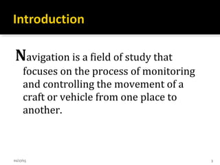
This document discusses inertial navigation sensor calibration. It provides an introduction to inertial navigation sensors and methods for calibrating accelerometers and gyroscopes. It describes the components of an inertial measurement unit and common calibration methods like the six position static test. Applications of inertial sensors in areas like navigation, tracking, and robotics are also mentioned.


