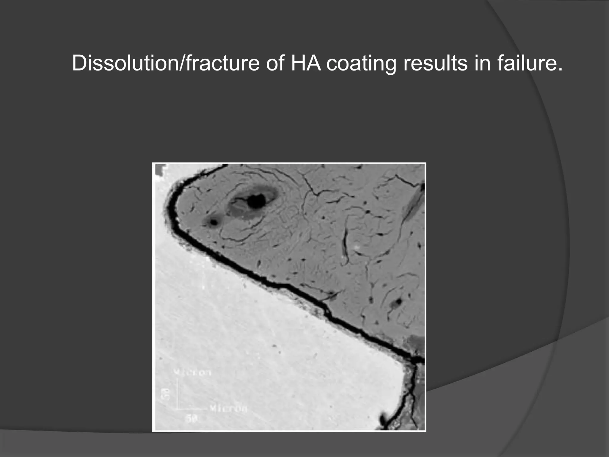
K.V.Arun
 Direct bone to implant contact
Process of Osseointegration
 Primary stability- mechanical
interlocking
 Contact osteogenesis- direct apposition
 Secondary stability- mineralized nodule
formation
(Berglundh,2003)
Forces acting on bone
 Favorable forces
Remodelling of bone
Woven bone formation
 Unfavorable forces
• excess load
 Microcracks- osteoclast activation
(Hansson &Werke, 2003)
 Insufficient remodeling-defect forms,
accumulate , coalesce, filled with fibrous tissue
(Misch 2001)
 Severe bone loss- implant failure
(Bruski, 1999)
Forces Acting on Bone/Implant
 Compressive forces
 Tensional forces
 Shear forces
 Stress= force/ surface area
 Forces may not be controlled
 Surface area?
 Compressive stress –beneficial
 Tensile stress - harmful
 Shear stress – most harmful
Primary Stability
 Implant
 Implant length
 Implant diameter
 Implant design
 Loading protocol
 Bone
 Quality, volume
 Density
 Surgical technique
Implant Length
 Length directly
proportional to surface
area
 Greater bone to implant
contact
 Longer implant- greater surface area-
greater stability
 Favorable crown/implant ratio
 Longer implants >10 mm compatible
with CSR
(Adell 1982, Lee 1995)
 D1 bone- bicortical stabilization
unnecessary as bone is homogeneous
 D2 , D3 bone- bone over heating
 D4 bone- apical areas too soft for local
compression stabilization
 Stress concentration -maximum ?
 Lateral stress distribution poor in short
implants
 Review on short implants <7mm
(Hagi D, Deporter DA)
 Threaded implants- shorter implants,
higher failure rates
 Sintered, porous implants- high success
rates >95%
 Short implants- 7mm or 9 mm
(Misch CE, 2005)
 Survival rate-99%
 Increase diameter, eliminate lateral
forces, splint implants.
Implant Diameter
 Related to surface area
 Anatomical limitations
 Traditionally wide implants >5mm
associated with greater failure
Wide Body Implants
 > 5mm in diameter
(Vanderweghe, Ackernman A, 2009)
 95.7% survival rates
 Used as rescue implants
 extraction sockets in poor primary stability
 poor bone quality
NDI implants
 <3.75 mm in dia
(Arisan V, Bolukbusu 2010)
 Overdenture in mandible
 94-100% survival rates
 Follow up- 1-9 years, CSR .95%
(Cho CS, Froum S)
 Impact of length and diameter
(Renourd F, Nisand D, 2006)
 Dense bone, textured implants, good
operator skill – short, wide, implants had
same survival rates as traditional
implants
 Influence of diameter and length on
early implant loss
(Olate S, Lynn MC, 2010)
 Early implant loss associated with short
implants
 Not associated with diameter
 Ultra short implants 5mm long, 5mm in
diameter in posterior areas
(Deporter D,2008)
 1-8 year follow up results
 Maxillary, mandibular failure rates 14.3
and 0%
Implant Design
 Macro design
 Body shape
 Thread
 Thread design
 Micro design
 Implant materials
 Surface morphology
 Surface coating
Implant Body Shape
 Cylindrical, tapered implants
 Other shapes not in use
 Tapered implant- 4 degree non parallel
30 degree maximum
 Tapered implants- increased
compressive forces
 Cylindrical implants- increased shear
forces
(Lemons, 1993)
 Cylindrical implants- increased failure
rates
(Misch, 2008)
Implant Threads
 Screw threads
 tapped
 self tapping
 Solid body press fit
 Sintered bead technology
Thread Geometry
 Increase bone implant contact area
○ Total vs functional surface area
 Stress distribution
 Stability
 Bone bridge from one thread to another
 Cusp like bone formation
 Heterogenous stress field
 Thread shapes available include; V-shape,
square shape, buttress and reverse buttress
shape (Boggan et al. 1999).
 Bone implant contact-
 increased in square threads
(Steinganga,2004)
 Density highest below threads
 Weakest- tip of threads
(Bolind,2005)
• Square, Buttress threads
◦ Axial load - dissipated
through compressive force.
(Bungardener, 2000)
 V shaped and reverse
buttress
◦ Axial load – dissipated
through compressive,
tensile and sheer force.
( Misch, 2005)
 Cancellous bone
 V shaped, broad square threads
 Significantly less stress
 Cortical bone
 No difference
(Geng 2004)
 Square thread least stress concentration
(Chun et al 2000)
 The face angle is
the angle between a
face of a thread and
a plane
perpendicular to the
long axis of the
implant.
• Face Angle
 Shear stress increased as face angle
increases
 V shaped, 30°
 Reverse buttress 15°
 V shaped, buttress
 Generates excess forces
 Defect formation
(Hansson & Werke 2003)
• Thread pitch refers to the
distance from the center
of the thread to the center
of the next thread,
measured parallel to the
axis of a screw (Jones
1964).
• It may be calculated by
dividing unit length by the
number of threads (Misch
et al. 2008).
Thread pitch
 Maximum effect on design variables
 Affects surface area
 Lower pitch- increased % BIC
 Less pitch- deceased stress
(Motoyosti, 2005)
 .8 mm pitch optimal for primary stability
*V shaped threads
 Shorter or longer pitch
* Unfavorable forces
 Affects cancellous more than cortical
bone
 Thread depth is defined as the distance
from the tip of the thread to the body of
the implant.
 Thread width is the distance in the same
axial plane between the coronal most
and the apical most part at the tip of a
single thread.
 Thread depth & width
 Affects implant surface area
 Deeper the thread- wider surface area of
implant
 Shallower thread- ease of placement
 Progressive thread design
 Greater depth apically, decrease
gradually in a coronal direction
 Increased load transfer to more flexible
cancellous bone
 Decreased cortical bone resorption
 Optimal thread depth - .34-.5mm
 Thread width- .18- .3 mm
 Depth more sensitive to peak stresses
(Abrahamsson, 2010)
Macrodesign: Summary
Crest module
 Traditionally smooth
 Soft tissue formation, less plaque
formation
 Sterile environment changes to open
oral cavity
 Thicker cortical bone- primary stability
 Increased force concentration
(Bozkoya, 2004)
 Microthreads in
crest module
 Insufficient data
 Postulated to reduce
crestal bone loss
(Kim 2009)
 Approaches to alter implant surfaces
can be classified as
 Physicochemical
 Morphologic or
 Biochemical.
(Ito et al.)
Surface materials
 Commercially pure titanium and Ti-6Al-
4V niobium
 Molybdenum & manganese
 Zirconia
 Surface energy
 Zeta potential
 Interfacial tension
 Surface charge
 Net positive or negative charge
 Surface composition
 Oxide layer
Physicochemical properties
 Zeta potential
○ Difference in potential between tightly bound
layers and diffuse layers
 Interfacial tension
 Wettability- property of interaction forces
between different materials and interaction
between cohesion forces within materials
(Mollers)
 Low wettability- low osteoblast cell
attachment and decreased collagen
production (Reddy 2000)
 Increased polar components –
increased osteoblast function
 Electrostatic interaction in biological
events -conducive to tissue integration.
(Baier RE et al., 1998)
 No selective cell adhesion
 Does not increase implant tissue
interface strength
(Puleo DA et al., 2006)
Surface Morphology
 Surface topography/morphological
characteristics.
 Chemical properties.
Surface Roughness
 Increased surface area of implant
adjacent to bone.
 Improved cell attachment to bone.
 Increased bone present at implant
interface.
 Increased biochemical interaction of
implant with bone.
• Smooth surfaces: Sa value < 0.5 μm (e.g.
polished abutment surface)
• Minimally rough surfaces: Sa value 0.5 to <
1.0 μm (e.g. turned implants)
• Moderately rough surfaces: Sa value 1.0 to
< 2.0 μm (e.g. most commonly used types)
• Rough surfaces: Sa value ≥ 2.0 μm (e.g.
plasma sprayed surfaces).
(Wennerberg and Albrektsson, 2009)
• Moderate roughness and roughness is
associated with implant geometry-
allowed for bone ongrowth and provided
mechanical interlocking (Berglungh et al.
2003, Franchi et al. 2005)
• Higher BIC and removal torque force
suggested enhanced secondary stability
compared to smooth and minimally
rough implants (Buser et al. 1991,
Wennerberg et al. 1996).
Morphology
 Based on texture
 Concave texture (mainly by additive
treatments like hydroxyapatite (HA) coating
and titanium plasma spraying)
 Convex texture (mainly by subtractive
treatment like etching and blasting)
Based on the orientation of surface irregularities
Isotropic surfaces: have the same topography
independent of measuring direction.
Anisotropic surfaces: have clear directionality and
differ considerably in roughness.
Surface coatings
 Chemical agents
 Biological agents
Chemical
 Al2 O3 and TiO2, with particle size
ranging from small, medium to large
(150-350 μm) grit.
 HA coating
 Obtain improved bone implant
attachment.
 Being osteoconductive in nature, more
bone deposition has been reported
Lower the corrosion rates of the same substrate
alloys.
Delamination of coating leads to failure of
implant
Dissolution/fracture of HA coating results in failure.
• Predisposes to plaque retention.
• Inflammatory reaction.
(Gross M 1999, Jansen, 1997)
Biological Coatings
 Cell adhesion molecules
 Biomolecules with demonstrated
osteotropic effects
Adhesion Molecules
 RGD sequence
 BMPR 2 peptide
Bioactive Proteins
 BMP
 PDGF
 TGF
Loading Protocol
 Immediate loading
 First longitudinal trial (Shitman,1990)
 Immediate , early loading in mandible
Esposito, 2009
 Immediate- within 1 week
 Early- 1 week to 2 months
 Conventional- > 2months
 Immediate and early can be done with
good success
* case selection
* operator skill
 Failure rates:
 early> immediate > conventional
 Primary stability- very important
Esposito, 2007
 Differences between immediate & early:
not clear
 More studies needed
Esposito, 2004
 Successful in mandible, dense bone
 Few well controlled RCT’s.
 Publication bias in immediately loaded
implants
(Polson, 2000)
 Trial aborted in UK due to unacceptable
failure rate
 Progressive loading
(Cannizaro,2003)
 Immediate provisionalisation
 Insertion torque- 40Ncm
 Large , multicentric trial
(Donati, Zollner, 2008)
 Insufficient information
 Risk of bias
Platform Switching
 Wide diameter implants-intro in late
1980s
 Fitted with standard diameter
abutments- showed no changes in
crestal bone levels around implants
 Concept
 Small diameter
prosthetic component
connected to larger
diameter implant
platform- creating a
90° step
(Lazzara RJ 2006)
 Long term studies (Wagenberg B 2010)
 advantage of platform switching in
preserving crestal bone levels.
 Recommended in anatomic sites where
minimum distance between implant and
adjacent units cannot be achieved.
Theories
1. Biomechanical theory
◦ Bone resorption limited by shifting stress concentration
zone away from crest and directing it along axis (Maeda
2007)
2. Placement of implant- abutment junction (IAJ) at
or below crestal bone level may cause vertical
bone resorption to reestablish biological width
(Hermann 2001).
3. Presence of inflammatory cell infiltrate at the IAJ
(Ericsson 1995) and Peri-implant microbiota.
Esposito- SR, 2007
 No evidence to show any implant better
than another
Implant survival rates
 Popelet A,Valet F
 63% DID NOT REPORT INDUSTRY
FUNDING
 66%-RISK OF BIAS
 Inclusion/ exclusion criteria
 Blinding
 Drop out rates not reported
 Survival rate significantly lower in
industry non funded studies
 Highest when funding undisclosed
Esposito 2004
 Bone quality, volume most important
TO BE CONTINUED……………………….

basics of implantology.ppt

  • 1.
  • 2.
     Direct boneto implant contact
  • 3.
    Process of Osseointegration Primary stability- mechanical interlocking  Contact osteogenesis- direct apposition  Secondary stability- mineralized nodule formation (Berglundh,2003)
  • 4.
    Forces acting onbone  Favorable forces Remodelling of bone Woven bone formation
  • 5.
     Unfavorable forces •excess load  Microcracks- osteoclast activation (Hansson &Werke, 2003)  Insufficient remodeling-defect forms, accumulate , coalesce, filled with fibrous tissue (Misch 2001)  Severe bone loss- implant failure (Bruski, 1999)
  • 6.
    Forces Acting onBone/Implant  Compressive forces  Tensional forces  Shear forces
  • 7.
     Stress= force/surface area  Forces may not be controlled  Surface area?
  • 8.
     Compressive stress–beneficial  Tensile stress - harmful  Shear stress – most harmful
  • 9.
    Primary Stability  Implant Implant length  Implant diameter  Implant design  Loading protocol  Bone  Quality, volume  Density  Surgical technique
  • 10.
    Implant Length  Lengthdirectly proportional to surface area  Greater bone to implant contact
  • 11.
     Longer implant-greater surface area- greater stability  Favorable crown/implant ratio  Longer implants >10 mm compatible with CSR (Adell 1982, Lee 1995)
  • 12.
     D1 bone-bicortical stabilization unnecessary as bone is homogeneous  D2 , D3 bone- bone over heating  D4 bone- apical areas too soft for local compression stabilization
  • 13.
  • 14.
     Lateral stressdistribution poor in short implants
  • 15.
     Review onshort implants <7mm (Hagi D, Deporter DA)  Threaded implants- shorter implants, higher failure rates  Sintered, porous implants- high success rates >95%
  • 16.
     Short implants-7mm or 9 mm (Misch CE, 2005)  Survival rate-99%  Increase diameter, eliminate lateral forces, splint implants.
  • 17.
    Implant Diameter  Relatedto surface area  Anatomical limitations
  • 18.
     Traditionally wideimplants >5mm associated with greater failure
  • 19.
    Wide Body Implants > 5mm in diameter (Vanderweghe, Ackernman A, 2009)  95.7% survival rates  Used as rescue implants  extraction sockets in poor primary stability  poor bone quality
  • 20.
    NDI implants  <3.75mm in dia (Arisan V, Bolukbusu 2010)  Overdenture in mandible  94-100% survival rates  Follow up- 1-9 years, CSR .95% (Cho CS, Froum S)
  • 21.
     Impact oflength and diameter (Renourd F, Nisand D, 2006)  Dense bone, textured implants, good operator skill – short, wide, implants had same survival rates as traditional implants
  • 22.
     Influence ofdiameter and length on early implant loss (Olate S, Lynn MC, 2010)  Early implant loss associated with short implants  Not associated with diameter
  • 23.
     Ultra shortimplants 5mm long, 5mm in diameter in posterior areas (Deporter D,2008)  1-8 year follow up results  Maxillary, mandibular failure rates 14.3 and 0%
  • 27.
    Implant Design  Macrodesign  Body shape  Thread  Thread design  Micro design  Implant materials  Surface morphology  Surface coating
  • 28.
    Implant Body Shape Cylindrical, tapered implants  Other shapes not in use  Tapered implant- 4 degree non parallel 30 degree maximum
  • 29.
     Tapered implants-increased compressive forces  Cylindrical implants- increased shear forces (Lemons, 1993)  Cylindrical implants- increased failure rates (Misch, 2008)
  • 30.
    Implant Threads  Screwthreads  tapped  self tapping  Solid body press fit  Sintered bead technology
  • 31.
    Thread Geometry  Increasebone implant contact area ○ Total vs functional surface area  Stress distribution  Stability
  • 32.
     Bone bridgefrom one thread to another  Cusp like bone formation  Heterogenous stress field
  • 33.
     Thread shapesavailable include; V-shape, square shape, buttress and reverse buttress shape (Boggan et al. 1999).
  • 34.
     Bone implantcontact-  increased in square threads (Steinganga,2004)  Density highest below threads  Weakest- tip of threads (Bolind,2005)
  • 35.
    • Square, Buttressthreads ◦ Axial load - dissipated through compressive force. (Bungardener, 2000)  V shaped and reverse buttress ◦ Axial load – dissipated through compressive, tensile and sheer force. ( Misch, 2005)
  • 36.
     Cancellous bone V shaped, broad square threads  Significantly less stress  Cortical bone  No difference (Geng 2004)  Square thread least stress concentration (Chun et al 2000)
  • 37.
     The faceangle is the angle between a face of a thread and a plane perpendicular to the long axis of the implant.
  • 38.
    • Face Angle Shear stress increased as face angle increases  V shaped, 30°  Reverse buttress 15°  V shaped, buttress  Generates excess forces  Defect formation (Hansson & Werke 2003)
  • 39.
    • Thread pitchrefers to the distance from the center of the thread to the center of the next thread, measured parallel to the axis of a screw (Jones 1964). • It may be calculated by dividing unit length by the number of threads (Misch et al. 2008).
  • 40.
    Thread pitch  Maximumeffect on design variables  Affects surface area  Lower pitch- increased % BIC  Less pitch- deceased stress (Motoyosti, 2005)
  • 41.
     .8 mmpitch optimal for primary stability *V shaped threads  Shorter or longer pitch * Unfavorable forces  Affects cancellous more than cortical bone
  • 42.
     Thread depthis defined as the distance from the tip of the thread to the body of the implant.  Thread width is the distance in the same axial plane between the coronal most and the apical most part at the tip of a single thread.
  • 43.
     Thread depth& width  Affects implant surface area  Deeper the thread- wider surface area of implant  Shallower thread- ease of placement
  • 45.
     Progressive threaddesign  Greater depth apically, decrease gradually in a coronal direction  Increased load transfer to more flexible cancellous bone  Decreased cortical bone resorption
  • 46.
     Optimal threaddepth - .34-.5mm  Thread width- .18- .3 mm  Depth more sensitive to peak stresses (Abrahamsson, 2010)
  • 48.
  • 49.
    Crest module  Traditionallysmooth  Soft tissue formation, less plaque formation
  • 50.
     Sterile environmentchanges to open oral cavity  Thicker cortical bone- primary stability  Increased force concentration (Bozkoya, 2004)
  • 51.
     Microthreads in crestmodule  Insufficient data  Postulated to reduce crestal bone loss (Kim 2009)
  • 53.
     Approaches toalter implant surfaces can be classified as  Physicochemical  Morphologic or  Biochemical. (Ito et al.)
  • 54.
    Surface materials  Commerciallypure titanium and Ti-6Al- 4V niobium  Molybdenum & manganese  Zirconia
  • 55.
     Surface energy Zeta potential  Interfacial tension  Surface charge  Net positive or negative charge  Surface composition  Oxide layer
  • 56.
    Physicochemical properties  Zetapotential ○ Difference in potential between tightly bound layers and diffuse layers  Interfacial tension  Wettability- property of interaction forces between different materials and interaction between cohesion forces within materials (Mollers)
  • 57.
     Low wettability-low osteoblast cell attachment and decreased collagen production (Reddy 2000)  Increased polar components – increased osteoblast function
  • 58.
     Electrostatic interactionin biological events -conducive to tissue integration. (Baier RE et al., 1998)  No selective cell adhesion  Does not increase implant tissue interface strength (Puleo DA et al., 2006)
  • 59.
    Surface Morphology  Surfacetopography/morphological characteristics.  Chemical properties.
  • 60.
    Surface Roughness  Increasedsurface area of implant adjacent to bone.  Improved cell attachment to bone.  Increased bone present at implant interface.  Increased biochemical interaction of implant with bone.
  • 62.
    • Smooth surfaces:Sa value < 0.5 μm (e.g. polished abutment surface) • Minimally rough surfaces: Sa value 0.5 to < 1.0 μm (e.g. turned implants) • Moderately rough surfaces: Sa value 1.0 to < 2.0 μm (e.g. most commonly used types) • Rough surfaces: Sa value ≥ 2.0 μm (e.g. plasma sprayed surfaces). (Wennerberg and Albrektsson, 2009)
  • 63.
    • Moderate roughnessand roughness is associated with implant geometry- allowed for bone ongrowth and provided mechanical interlocking (Berglungh et al. 2003, Franchi et al. 2005) • Higher BIC and removal torque force suggested enhanced secondary stability compared to smooth and minimally rough implants (Buser et al. 1991, Wennerberg et al. 1996).
  • 65.
    Morphology  Based ontexture  Concave texture (mainly by additive treatments like hydroxyapatite (HA) coating and titanium plasma spraying)  Convex texture (mainly by subtractive treatment like etching and blasting)
  • 66.
    Based on theorientation of surface irregularities Isotropic surfaces: have the same topography independent of measuring direction. Anisotropic surfaces: have clear directionality and differ considerably in roughness.
  • 67.
    Surface coatings  Chemicalagents  Biological agents
  • 68.
    Chemical  Al2 O3and TiO2, with particle size ranging from small, medium to large (150-350 μm) grit.  HA coating
  • 69.
     Obtain improvedbone implant attachment.  Being osteoconductive in nature, more bone deposition has been reported
  • 70.
    Lower the corrosionrates of the same substrate alloys. Delamination of coating leads to failure of implant
  • 71.
    Dissolution/fracture of HAcoating results in failure.
  • 72.
    • Predisposes toplaque retention. • Inflammatory reaction. (Gross M 1999, Jansen, 1997)
  • 73.
    Biological Coatings  Celladhesion molecules  Biomolecules with demonstrated osteotropic effects
  • 74.
    Adhesion Molecules  RGDsequence  BMPR 2 peptide
  • 75.
  • 76.
    Loading Protocol  Immediateloading  First longitudinal trial (Shitman,1990)  Immediate , early loading in mandible
  • 77.
    Esposito, 2009  Immediate-within 1 week  Early- 1 week to 2 months  Conventional- > 2months
  • 78.
     Immediate andearly can be done with good success * case selection * operator skill  Failure rates:  early> immediate > conventional  Primary stability- very important
  • 79.
    Esposito, 2007  Differencesbetween immediate & early: not clear  More studies needed
  • 80.
    Esposito, 2004  Successfulin mandible, dense bone  Few well controlled RCT’s.
  • 81.
     Publication biasin immediately loaded implants (Polson, 2000)  Trial aborted in UK due to unacceptable failure rate
  • 82.
     Progressive loading (Cannizaro,2003) Immediate provisionalisation  Insertion torque- 40Ncm
  • 83.
     Large ,multicentric trial (Donati, Zollner, 2008)  Insufficient information  Risk of bias
  • 84.
    Platform Switching  Widediameter implants-intro in late 1980s  Fitted with standard diameter abutments- showed no changes in crestal bone levels around implants
  • 85.
     Concept  Smalldiameter prosthetic component connected to larger diameter implant platform- creating a 90° step (Lazzara RJ 2006)
  • 86.
     Long termstudies (Wagenberg B 2010)  advantage of platform switching in preserving crestal bone levels.  Recommended in anatomic sites where minimum distance between implant and adjacent units cannot be achieved.
  • 87.
    Theories 1. Biomechanical theory ◦Bone resorption limited by shifting stress concentration zone away from crest and directing it along axis (Maeda 2007) 2. Placement of implant- abutment junction (IAJ) at or below crestal bone level may cause vertical bone resorption to reestablish biological width (Hermann 2001). 3. Presence of inflammatory cell infiltrate at the IAJ (Ericsson 1995) and Peri-implant microbiota.
  • 88.
    Esposito- SR, 2007 No evidence to show any implant better than another
  • 89.
    Implant survival rates Popelet A,Valet F  63% DID NOT REPORT INDUSTRY FUNDING  66%-RISK OF BIAS
  • 90.
     Inclusion/ exclusioncriteria  Blinding  Drop out rates not reported
  • 91.
     Survival ratesignificantly lower in industry non funded studies  Highest when funding undisclosed
  • 92.
    Esposito 2004  Bonequality, volume most important
  • 93.