The Architecture Design for Find Outing Vehicle Position System using Communication Networks

Abstract: Intelligent Transportation System is a crucial part of information construction. With the increasing city holdings of cars, there are more and more traffic jams, so requirements are that Intelligent Transportation needs more improvement. The key technology Of Intelligent Transportation is Vehicle positioning System, while the key of which is positioning System. Nowadays the most widely used positioning system is the Global Positioning System (GPS), which is a system consisting 24 satellites whose searching area embrace the globe. It can ensure that more than 4 satellites will be observed at one time, no matter what time it is or where you are, thus making sure that they can collect the longitude and latitude of the view point, and furthermore realizing the function of navigation, positioning, and time service Keywords: ARM9, GSM, GPS.

Recommended
More Related Content
What's hot
What's hot (20)
Viewers also liked
Viewers also liked (17)
Similar to The Architecture Design for Find Outing Vehicle Position System using Communication Networks
Similar to The Architecture Design for Find Outing Vehicle Position System using Communication Networks (20)
More from Kumar Goud
More from Kumar Goud (15)
Recently uploaded
Recently uploaded (20)
The Architecture Design for Find Outing Vehicle Position System using Communication Networks
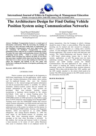
- 1. International Journal of Ethics in Engineering & Management Education Website: www.ijeee.in (ISSN: 2348-4748, Volume 1, Issue 10, October 2014) The Architecture Design for Find Outing Vehicle Position System using Communication Networks Sayed Shoyeb Mohiuddin1 B. Satish Chandra2 M.Tech (Embedded System) Associate Professor, Dept of ECE Jyothishmathi Institute of Technology and Science Jyothishmathi Institute of Technology and Science Sd.shoyeb@gmail.com satishbolishetti@gmail.com 16 Abstract: Intelligent Transportation System is a crucial part of information construction. With the increasing city holdings of cars, there are more and more traffic jams, so requirements are that Intelligent Transportation needs more improvement. The key technology Of Intelligent Transportation is Vehicle positioning System, while the key of which is positioning System. Nowadays the most widely used positioning system is the Global Positioning System (GPS), which is a system consisting 24 satellites whose searching area embrace the globe. It can ensure that more than 4 satellites will be observed at one time, no matter what time it is or where you are, thus making sure that they can collect the longitude and latitude of the view point, and furthermore realizing the function of navigation, positioning, and time service Keywords: ARM9, GSM, GPS. I.INTRODUCTION Passive systems were developed in the beginning to fulfill these requirements. For the applications which require real time location information of the vehicle, these systems can’t be employed because they save the location information in the internal storage and location information can only be accessed when vehicle is available. To achieve Automatic Vehicle Location system that can transmit the location information in real time, Active systems are developed. Real time vehicular tracking system incorporates a hardware device installed in the vehicle (In-Vehicle Unit) and a remote Tracking server. The information is transmitted to Tracking server using GSM/GPRS modem on GSM network by using SMS or using direct TCP/IP connection with Tracking server through GPRS. Tracking server also has GSM/GPRS modem that receives vehicle location information via GSM network and stores this information in database. This information is available to authorized users of the system via website over the internet. In 1976 GM introduced SDM module (Sensing and Diagnostic Module), which was improved to so called DERM (Diagnostic and Energy Reserve Module) in 1990. The main target of this module consists of recording and saving data from measuring sensors including error messages at the time when the airbag is activated. In this modern, fast moving and insecure world, it is become a basic necessity to be aware of one’s safety. Maximum risks occur in situations where in an employee navels for money transactions. Also the Company to which e belongs should be aware if there is some problem. What the person traveling can be tracked and also secured in emergency. Here’s a system that functions as a asking and a security system. It’s the intelligent vehicle control for critical remote location application. This system an deal with both pace and security. The Vehicle Monitoring and Security System is a GPS based vehicle asking system that is used for security applications as well. The project uses two main underlying concepts. These are GPS (Global Positioning System) and GSM (Global system for Mobile Communication). The main application of this system in this context is tracking the vehicle to which the GPS is connected, giving the information about position whenever required. This is done with the help of the GPS satellite and the GPS module attached to the vehicle which needs to be tracked. The GPS antenna present in the GPS module receives the information from the GPS. BLOCK DIAGRAM: ARM9 controller GPS module GSM module UART module
- 2. International Journal of Ethics in Engineering & Management Education Website: www.ijeee.in (ISSN: 2348-4748, Volume 1, Issue 10, October 2014) 17 II.HARDWARE DESIGN ARM9 CONTROLLER: The fundamental problem with reducing the CPI relative to a 3-stage core is related to the von Neumann bottleneck - and stored-program computer with a single instruction and data memory will have its performance limited by the available memory bandwidth. A 3-stage ARM core accesses memory on (almost) every clock cycle either to fetch an instruction or to transfer data. Simply tightening up on the few cycles where the memory is not used will yield only a small performance gain. To get a significantly better CPI the memory system must deliver more than one value in each clock cycle either by delivering more than 32 bits per cycle from a single memory or by having separate memories for instruction and data accesses. As a result of the above issues, higher performance ARM cores employ a 5-stage pipeline and have separate instruction and data memories. Breaking instruction execution down into five components rather than three reduces the maximum work which must be completed in a clock cycle, and hence allows a higher clock frequency to be used (provided that other system components, and particularly the instruction memory, are also redesigned to operate at this higher clock rate). The separate instruction and data memories (which may be separate caches connected to a unified instruction and data main memory) allow a significant reduction in the core's CPI.A typical 5- stage ARM pipeline is that employed in the ARM9TDMI. The organization of the ARM9TDMI is illustrated in Figure. The ARM processors which use a 5-stage pipeline have the following pipeline stages: Fetch Decode Execute instruction fetch Thumb decompress instruction fetch ARM decode reg read reg shift/ALU write reg shift/ALU write r. read decode data memory access Fetch Decode Execute Memory Write ARM7TDMI: ARM9TDMI: Fig 1: pipeline in ARM architectures • Fetch—The instruction is fetched from memory and placed in the instruction pipeline. • Decode—The instruction is decoded and register operands read from the register file. There are three operand read ports in the register file, so most ARM instructions can source all their operands in one cycle. • Execute—An operand is shifted and the ALU result generated. If the instruction is a load or store the memory address is computed in the ALU. • Buffer/data—Data memory is accessed if required. Otherwise the ALU result is simply buffered for one clock cycle to give the same pipeline flow for all instructions. • Write-back—The results generated by the instruction are written back to the register file, including any data loaded from memory. ARM9 implements Harvard architecture: · Increases available memory bandwidth · Instruction memory interface · Data memory interface · Simultaneous accesses to instruction and data memory can be achieved · 5-stage pipeline The ARM architecture features are: 1. load-store architecture 2. fixed-length 32-bit instructions 3. 3-address instruction formats Load-store architecture: · Special instructions to access memory · First operand is loaded from the memory into a register. · Second operand is loaded from the memory into a register · Operation is performed on the registers · Result is written into a register, and has to be explicitly stored back into memo Fig 2: Load-Store Architecture Fixed-Length 32-bit instructions: Use same number of bits to encode each instruction in the instruction set architecture. It is simple to decode hence reduces the amount of decode logic required and the latency in the decode logic. Easily predict the location of the next instruction to be executed (assuming that the current instruction is not a branch), this makes it easier for the processor to use pipelining to improve performance by overlapping the execution of multiple instructions.
- 3. International Journal of Ethics in Engineering & Management Education Website: www.ijeee.in (ISSN: 2348-4748, Volume 1, Issue 10, October 2014) 18 Operating Modes: ARM920T supports seven modes of operation: · User (usr): The normal ARM program execution state · FIQ (fiq): Designed to support a data transfer or channel process · IRQ (irq): Used for general-purpose interrupt handling · Supervisor (svc): Protected mode for the operating system · Abort mode (abt): Entered after a data or instruction Prefetch abort · System (sys): A privileged user mode for the operating system · Undefined (und): Entered when an undefined instruction is executed Mode changes can be made using the control of software, or may be brought about by external interrupts or exception processing. Most application programs will execute in User mode. The non-user modes' known as privileged modes-are entered in order to service interrupts or exceptions, or to access protected resources. Registers: ARM920T has a total of 37 registers - 31 general-purpose 32- bit registers and six status registers - but these cannot all be seen at once. The processor state and operating mode decides which registers are available to the programmer. 1 The ARM State Register Set: In ARM state, 16 general registers and one or two status registers are visible at any one time. In privileged (non-User) modes, mode-specific banked registers are switched in. Figure 3 shows which register is available in each mode: the banked registers are marked with a shaded triangle. The ARM state register set contains 16 directly accessible registers: R0 to R15. All of these except R15 are general-purpose, and may be used to hold either data or address values. In addition to these, there is a seventeenth register used to store status information. Fig 3: ARM State register set The relationship between ARM and THUMB state registers are as below:- · THUMB state R0-R7 and ARM state R0-R7 are identical · THUMB state CPSR and SPSRs and ARM state CPSR and SPSRs are identical · THUMB state SP maps onto ARM state R13 · THUMB state LR maps onto ARM state R14 · The THUMB state Program Counter maps onto the ARM state Program Counter (R15) THE PROGRAM STATUS REGISTERS: The ARM920T contains a Current Program Status Register (CPSR), plus five Saved Program Status Registers (SPSRs) for use by exception handlers. These register's functions are: · Hold information about the most recently performed ALU operation · Control the enabling and disabling of interrupts · Set the processor operating mode II.WIRELESS COMMUNICATION: GLOBAL POSTIONING SYSTEM: A. Basic concept of GPS operation A GPS receiver calculates its position by carefully timing the signals sent by the constellation of GPS satellites high above the Earth. Each satellite continually transmits messages containing the time the message was sent, a precise orbit for the satellite sending the message (the ephemeris), and the general system health and rough orbits of all GPS satellites (the almanac). These signals travel at the speed of light through outer space, and slightly slower through the atmosphere. The receiver uses the arrival time of each message to measure the distance to each satellite, from which it determines the position of the receiver (conceptually the intersection of spheres - see trilateration ) The resulting coordinates are converted to more user-friendly forms such as latitude and longitude, or location on a map, then displayed to the user.
- 4. International Journal of Ethics in Engineering & Management Education Website: www.ijeee.in (ISSN: 2348-4748, Volume 1, Issue 10, October 2014) 19 It might seem that three satellites would be enough to solve for a position, since space has three dimensions. However, a three satellite solution requires the time be known to a nanosecond or so, far better than any non-laboratory clock can provide. Using four or more satellites allows the receiver to solve for time as well as geographical position, eliminating the need for a super accurate clock. In other words, the receiver uses four measurements to solve for four variables: x, y, z, and t. While many GPS applications have no particular use for this (very accurate) time, it is used in some GPS applications such as time transfer, and it is the only variable of interest in some applications, such as traffic signal timing. Although four satellites are required for normal operation, fewer may be needed in some special cases. If one variable is already known (for example, a ship or plane may already know its altitude), a receiver can determine its position using only three satellites. Also, in practice, receivers use additional clues (Doppler shift of satellite signals, last known position, dead reckoning, inertiral navigation, and so on) to give degraded answers when fewer than four satellites are visible.To provide an introductory description of how a GPS receiver works, errors will be ignored in this section. Using messages received from a minimum of four visible satellites, a GPS receiver is able to determine the satellite positions and time sent. The x, y, and z components of position and the time sent are designated as where the subscript i denotes the satellite number and has the value 1, 2, 3, or 4. Knowing the indicated time the message was received , the GPS receiver can compute the indicated transit time, of the message. III.GSM MODEM GSM also pioneered a low-cost, to the network carrier, alternative to voice calls, the Short t message service (SMS, also called "text messaging"), which is now supported on other mobile standards as well. Another advantage is that the standard includes one worldwide Emergency telephone number, 112. This makes it easier for international travelers to connect to emergency services without knowing the local emergency number. The GSM Network: GSM provides recommendations, not requirements. The GSM specifications define the functions and interface requirements in detail but do not address the hardware. The GSM network is divided into three major systems: the switching system (SS), the base station system (BSS), and the operation and support system (OSS). a) The Switching System: The switching system (SS) is responsible for performing call processing and subscriber-related functions. The switching system includes the following functional units. · Home location register (HLR): The HLR is a database used for storage and management of subscriptions. The HLR is considered the most important database, as it stores permanent data about subscribers, including a subscriber's service profile, location information, and activity status. When an individual buys a subscription from one of the PCS operators, he or she is registered in the HLR of that operator. · Mobile services switching center (MSC): The MSC performs the telephony switching functions of the system. It controls calls to and from other telephone and data systems. It also performs such functions as toll ticketing, network interfacing, common channel signaling, and others. · Visitor location register (VLR): The VLR is a database that contains temporary information about subscribers that is needed by the MSC in order to service visiting subscribers. The VLR is always integrated with the MSC. When a mobile station roams into a new MSC area, the VLR connected to that MSC will request data about the mobile station from the HLR. Later, if the mobile station makes a call, the VLR will have the information needed for call setup without having to interrogate the HLR each time. · Authentication center (AUC): A unit called the AUC provides authentication and encryption parameters that verify the user's identity and ensure the confidentiality of each call. The AUC protects network operators from different types of fraud found in today's cellular world. · Equipment identity register (EIR): The EIR is a database that contains information about the identity
- 5. International Journal of Ethics in Engineering & Management Education Website: www.ijeee.in (ISSN: 2348-4748, Volume 1, Issue 10, October 2014) 20 of mobile equipment that prevents calls from stolen, unauthorized, or defective mobile stations. The AUC and EIR are implemented as stand-alone nodes or as a combined AUC/EIR node. b) The Base Station System (BSS): All radio-related functions are performed in the BSS, which consists of base station controllers (BSCs) and the base transceiver stations (BTSs). · BSC: The BSC provides all the control functions and physical links between the MSC and BTS. It is a high-capacity switch that provides functions such as handover, cell configuration data, and control of radio frequency (RF) power levels in base transceiver stations. A number of BSCs are served by an MSC. · BTS: The BTS handles the radio interface to the mobile station. The BTS is the radio equipment (transceivers and antennas)needed to service each cell in the network. A groupof BTSs are controlled by a BSC. The Operation and Support System The operations and maintenance center (OMC) is connected to all equipment in the switching system and to the BSC. The implementation of OMC is called the operation and support system (OSS). The OSS is the functional entity from which the network operator monitors and controls the system. The purpose of OSS is to offer the customer cost-effective support for centralized, regional and local operational and maintenance activities that are required for a GSM network. An important function of OSS is to provide a network overview and support the maintenance activities of different operation and maintenance organizations. For sending SMS in text Mode: AT+CMGF=1 press enter AT+CMGS=”mobile number” press enter Once The AT commands is given’ ’ prompt will be displayed on the screen. Type the message to send via SMS. After this, press “ctrl +Z” to send the SMS. If the SMS sending is successful, “ok” will be displayed along with the message number. For reading SMS in the text mode: AT+CMGF=1 Press enter AT+CMGR= no. Number (no.) is the message index number stored in the sim card. For new SMS, URC will be received on the screen as +CMTI: SM ‘no’. Use this number in the AT+CMGR number to read the message. IV.CONCLUSION The design of this paper-design and implementation of intelligent vehicle positioning system based on ARM9, a combination of GPS and GSM can track the information of the vehicle such as the position time to time and it can cross check with the boundary limits of the area and can generate an SMS alarm to the appropriate authorities so that necessary action can be taken further. As a result we can design the position based vehicle tracking system which is intelligent and which is convenient to control the traffic. REFERENCES [1]. E. D. Kaplan and C. J. Hegarty, Understanding GPS Principles and Applications, 2nd ed. Norwood, MA: Artech House, 2006. [2]. S. E. Shladover and S. K. Tan, “Analysis of vehicle positioning accuracy requirements for communication-based cooperative collision warning,” J. Intell. Transp. Syst., Technol., Plan., Oper., vol. 10, no. 3, pp. 131–140,2006. [3]. B. Hofmann-Wellenhof, H. Lichtenegger, and J. Collins, Global Positioning System Theory and Practice, 5th ed. New York: Springer- Verlag,2001. [4]. F. V. Diggelen, A-GPS : Assisted GPS, GNSS, and SBAS Boston. Boston, MA: Artech House, 2009. [5]. N. Patwari, A. O. Hero, III, M. Perkins, N. S. Correal, and R. J. O’Dea, “Relative location estimation in wireless sensor networks,” IEEE Trans. Signal Process., vol. 51, no. 8, pp. 2137–2148, Aug. 2003. [6]. A. Benslimane, “Localization in vehicular ad-hoc networks,” in Proc. Syst. Commun., Montreal, QC, Canada, 2005, pp. 19–25.