IIBE ppt at Lucknow dt 25.05.18
•Download as PPTX, PDF•
1 like•420 views

There was a Bridge 2018 Conference on Innovative Technologies of Bridges organised by IIBE at Lucknow. During the conference held on 25.05.18 this paper was presented by Rajesh Prasad, ED Metro RVNL.

Recommended
Recommended
More Related Content
What's hot
What's hot (20)
Similar to IIBE ppt at Lucknow dt 25.05.18
Similar to IIBE ppt at Lucknow dt 25.05.18 (20)
More from Rajesh Prasad
More from Rajesh Prasad (20)
Recently uploaded
Recently uploaded (20)
IIBE ppt at Lucknow dt 25.05.18
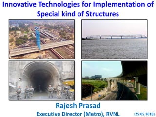
- 1. Innovative Technologies for Implementation of Special kind of Structures Rajesh Prasad Executive Director (Metro), RVNL (25.05.2018)
- 2. • Special kind of Structures :- –Cable Stayed Bridge –Bhagirathi Rail Bridge –Execution of Rail tunnel • Restoration of Vivekananda flyover • Safety during construction - Experience Scope
- 3. IT (Innovative Technology) and/or IT (Information Technology) = IT (India Tomorrow) - Hon’le Prime Minister
- 4. CABLE STAYED BRIDGE – few facts Engineers constructed the first pure cable- stayed bridges in Europe following the close of World War II, but the basic design dates back to the 16th century. Today, cable-stayed bridges are a popular choice. They require less steel cable, are faster to build and incorporate more precast concrete/steel sections.
- 5. • Length : 825 m • Longest Span 457m • 28.6 m width – 8 lane traffic • Post tensioned concrete box girders • Steel pylon SOME OF THE WORLD WIDE CABLE STAYED BRIDGES Image Name Span No. of pylons Year comp Country Russky Bridge 1104 m 2 2012 Russia Sutong Yangtze River Bridge 1088 m 2 2008 China Stonecutters Bridge 1018 m 2 2009 China Edong Yangtze River Bridge 926 m 2 2010 China Tatara Bridge 890 m 2 1999 Japan Pont de Normandie 856 m 2 1995 France Millau Bridge 342 m 2 2004 France Vidyasagar Setu, Kolkata Rajiv Gandhi Sea Link, Mumbai • Cable Stayed Main Bay. • Concrete – steel precast segment at either end. • Length 5.6 Kms. • Longest Span 2 x 250m • Commissioned in 2009
- 6. Brooklyn Bridge, New York
- 7. CABLE STAYED BRIDGE 4-LANE CABLE STAYED BRIDGE BARDDHAMAN VIEW OF MODEL
- 8. Suspension bridge Cable-Stayed bridge, FAN design CABLE-STAYED BRIDGE Cable-Stayed bridge, HARP design
- 9. Cable Stayed Bridge Suspension Bridge No. of Towers Any Restricted to 2 Requirements of Cable < 1000 m Less More Stiffness Higher Lesser Deflection Lesser Higher Construction time Lesser Higher
- 10. Barddhaman Yard - occupied with piers, arches and future yard remodeling not possible.
- 11. Clear Span(ABT to ABT): 184.428m Main span length : 124.163 m Side span length : 64.536 m No of cable planes : 3 Type of cable in main span : Harp pattern No. of cables in main span : 9 per plane No. of cable per side span : 9 per plane Spacing between cables in main span : 12 m Spacing between the cables in side span : 6.881 m Hight of pylon : 62.329 m Clearance above rail track: 6.5 m Maximum height of road surface from rail track level: 7.5 M (Road surface to bottommost part of superstructure = 1 m) BARDDHAMAN CABLE STAYED BRIDGE DETAILS
- 12. Group-A/ Rajdhani Route 8 Nos of Platforms Busy Yard with 10 BG tracks Completely Electrified Section Restricted height in approach. Connected to GT Road on One SIDE WITH TWO APPROACH ARMS Connected to KATWA-KALNA Road on the Other Side with Two Approach Arms. Busy approach in City. CHALLENGES ENCOUNTERED…
- 13. • Length of Cantilever deck : 124.163 Mtr. • No. of Segment in deck : 11 nos. (1 Segment ~ 12 M) • Deck Segments erected by special type of D.E.C. • Capacity of D.E.C : About 75 MT • Approximate time required for Launching main span – 1 SEGMENT - 27 Days IMPORTANT FEATURES OF DECK AND PYLON ERECTION
- 14. • Height of the pylon - dictated by stability analysis & economics of the bridge. • A tall pylon will minimize the compression introduced into the steel deck system, but may increase the length of cable used. A short pylon will introduce undesirable compressive forces into the steel deck structure. • The cross section is sized for not only strength and deflection requirements, but also to accommodate a stressing and inspection route. Height fixed as 54.768m. Box - 2.5MX2.0M box STRUCTURAL DESIGN
- 15. Pile = 62 nos.1.5 m diameter 35m/25 m long pile (M 35 concrete) Pile Cap = 28.9 m x 6.7 m for CP1 37.9 m x 10.9 m for pylon 28.9 m x 10.9 m for CP2 (each 2.5 m high) Pier = 27.9 m x 4 m for CP1 28.2 m x 2.5 m for pylon 28.2 m x 2 m for CP2 (each 7 m high) Pylon = 3 Nos 2 m x 2.5 m x 54.76 m steel pylon above deck Back Span deck = 2 Nos. 68.26 m x 10.35 m x 0.75 m deck slab with one no. 68.26 m x 2.50 m x 2 m RC beam and two no. 68.26 m x 2.5 m x 1.8 m RC beam Steel Deck = 1 No. 120.16 m x 2 m x 1.21 m (MG-2) 2 Nos. 120.16 m x 2 m x 0.69 m (MG1) 60 nos. 10.85 m x 0.45 m (CG1) 2 nos. 120.16 m x 12.85 m x 0.25 m thick RCC deck slab. SALIENT QUANTITIES FOR CABLE STAYED BRIDGE
- 16. Stay Cables = 180 MT Reinforcement: = 1298 MT Structural Steel (E410) = 1881 MT Structural Steel (E250) = 280 MT Concrete M50 Grade: = 1752 Cum for piers, RC beams, deck slabs Concrete M60 Grade = 60 Cum for pedestals SALIENT QUANTITIES FOR CABLE STAYED BRIDGE
- 18. • LARSA 4D model for design • Wind tunnel test • Use of precast RCC slabs to avoid scaffolding on deck • Composite structures for easier construction • Monolithic Back Span • Durable painting by epoxy based paint of Akzonobel • Erection scheme • LUSAS model for Construction Stage Analysis • Geometry Control during execution. FEATURES
- 19. • Develops and uses advanced software for the analysis and design of bridges and structures based on the finite element method. • LARSA 4D bridge series – recognised as premier software with innovative tools and simulation models. LARSA 4D LARSA LARSA 98 LARSA LARSA 4D 1980’s 1990’s 2000’s 2010
- 20. Stage 16 • Max moment in Pylon. Utilization ratio <1 Bending Moment diagram (Dead Load + SIDL)
- 21. Stage 16 • Max moment in Pylon. Utilization ratio <1 Max. deflection is 208 mm (with lane reduction it will become 166mm) Bending Moment diagram (Two Tracks of 70R wheeled)
- 23. Model Design and Details of Sectional Model Model Scale : 1: 40 and blockage is about 5.9% Length of model: 1440mm long Width of model: 692.5mm Aspect Ratio ( length to width ratio): 2.08
- 24. w Lift Drag Wind Angle of Incidence Moment WDD ACUF 2 2 1 wLL BCUF 2 2 1 wMM CBUF 22 2 1 WIND INDUCED FORCES ON A BRIDGE DECK
- 25. • Model Design • Model Fabrication and mounting • Instrumentation ( pasting of strain guages in three component balance) • Calibration of Strain guage balance • Wind tunnel test at different angle of attack, wind speed Steps involved in Wind Tunnel Testing CONCLUSION OF WIND TUNNEL • The basic wind speed for design is to be taken as 47m/s at the location of bridge as per the wind given in IS:875 – Part 3 and IRC:6 • The terrain roughness for the bridge design has been taken as TC-I or plain terrain as per IRC:6 and wind forces in the transverse longitudinal and vertical directions have been computed as per IRC:6. • The bridge deck is not likely to be susceptible to galloping oscillation in vertical mode and shall flutter in first torsional mode. • The bridge deck is not susceptible to classical flutter.
- 26. • In order to avoid the problem of shuttering / de-shuttering for deck slab over electrified tracks and to ensure proper finish of concrete, the deck slab has been designed consisting of a precast slab and a cast-in-situ portion. The precast slab is placed over the cross girders by the Deck Erection Crane (DEC) and the cast-in- situ concrete is poured after completion of reinforcement and shear connector works. PRECAST DECK SLAB
- 27. Bed for Precast Slab Casting Precast Slab Reinforcement Trial of Precast Slabs in YardStacked Precast Slabs PRECAST DECK SLAB
- 28. Trial of Precast Slabs in Yard Erection of Precast Slabs PRECAST DECK SLAB
- 30. •Due to large spans, there are massive RCC Piers, pile caps and deck. • Size of the pile cap is as large as 413SQM X2.5M • Size of RCC pier is as large as 111SQMX7M • Volume of Back span Concrete is 2045CUM • Staging 800MT •Massive structures of high grade concrete need special precautions for manufacture, transport and placement of concrete and for holding of reinforcement cages for safety of workers. •Massive Back Span requires a very sturdy staging arrangement which has to support the back span till all the Stay cables are fixed and stressed. CONCRETE WORK AND MONOLITHIC BACK SPAN
- 33. PAINT & PAINTING SCHEME Maintenance-free painting scheme with a design life of 40+ years. The painting scheme and supervision by M/s Akzo Nobel and has a warranty period of 25 years for the painted structure.
- 35. Typical Deck Erection Cycle For One Panel SL No. Action Day 1. Erection of MG2 1 2. Erection of MG1 1 3. Erection of 6 nos. cross girder 3 4. Fixing of working platform, safety net and installation & stressing of cable 3 5. Erection of precast panels 2 6. Fixing of reinforcement, side formwork and concreting 3 7. Curing & Moving of DEC and other preparatory works 14 TOTAL 27
- 36. With the detailed micro-planning, it was estimated that the construction of the deck over the yard (Panels 2 to 9) would take approximately 200 days. Accordingly, the requirement for blocks was submitted to Railway, and the 1st block was availed on 16-8-2015 and last block on 29-02-2016, i.e. the work within the Railway Yard was completed within 197 days Deck Erection Cycle
- 37. Deck Erection Crane VIEW OF ERECTED DEC AT PANEL-5
- 38. PARALLEL STRAND SYSTEM Freyssinet’s Parallel Strand System (PSS) stay cables - which has a design life of 100 years and is the most advanced and durable stay cable system in the world today. There are 3 planes of stay cables with 18 cables each. Sensors for permanent monitoring of deflections and stresses during service condition, are also being installed in 6 stays subjected to heavy loads. Isotension® Method
- 40. • Vibration control dampers have been installed in long stay cables (> 80m) as per CIP recommendations • In order to reduce the effect of fatigue on the stay cables due to oscillations induced by wind or other external phenomena, stay cables of more than 80m length have been provided with Internal Radial Dampers (IRD). 15 such dampers have been installed on the stays • IRD is composed of three hydraulic pistons placed at 120° angle around the cable. The inner end of the pistons is fixed with a pin joint on a collar compacting the strand bundle. Their outer end is fixed with pin joints to a metallic tube called the guide tube. The damper is fixed rigidly to the guide tube. • The available stroke for the transverse displacements is +/- 40mm. INTERNAL RADIAL DAMPERS
- 42. Stay Cable Installation & Stressing FIXING STRAND LENGTHS • INITIAL SURVEY OF THE ACTUAL “AS-BUILT” POSITIONS OF THE ANCHORAGE NODES IS DONE. CORRECTIONS TO THE STRAND LENGTHS, IF REQUIRED, ARE DONE. ANCHORAGE INSTALLATION • THE FIXED ANCHORAGES ARE INSTALLED AT THE PASSIVE ENDS, AND THE ADJUSTABLE ANCHORAGES ARE INSTALLED AT THE ACTIVE END DUCT & MASTER STRAND INSTALLATION • MASTER STRAND IS THREADED INTO THE HDPE DUCT, AND LIFTED BY MEANS OF A HOISTING COLLAR. THE MASTER STRAND IS THEN THREADED INTO THE ANCHORAGES AND STRESSED AS PER THE REQUIREMENT STRESSING • THE BALANCE STRANDS ARE CUT TO REQUIRED LENGTH AND HOISTED INTO POSITION, AND STRESSED TO THE REQUIRED FORCE FINISHING WORKS • AFTER COMPLETION OF FINAL STRESSING AND CLEARANCE FROM DESIGNER, CUTTING & BLOCKING OF JAWS, CLOSING & WAXING OF ANCHORAGES, DAMPER INSTALLATION, ETC. ARE DONE
- 43. • For monitoring of the structural health of the bridge during its service life, 6 nos. sensors have been installed on the stay cables subjected to maximum loads. The ROBO Control System of M/s Mageba is being used for the purpose. • The structural monitoring system issues alarm notification based on measurements by the on-structure instrumentation when pre-defined threshold values of structural loads are passed. Alarm criteria will be configured based on the structural design of the bridge MONITORING SYSTEM
- 45. Analysis Model • Analysis has been done using finite element analysis software LUSAS. • Deck is modeled as grillage of longitudinal and transverse members. • Deck is integral at P1 and CP2. At CP1 pin support with longitudinal free movement is used representing the Guided PTFE bearings. • At P1 and CP2, elastic spring supports representing the pile stiffness are used.
- 46. CABLES PYLON PILECAP AND PILE TEMPORARY SUPPORTS PIN SUPPORT LUSAS model of the Bridge Analysis Model CP1 CP2P1
- 47. Analysis Model Isometric View of the model
- 48. SECTION PROPERTIES Sr no Component C/S Area m2 M.I. Y-Y m4 M.I. Z-Z m4 1 Longitudinal beam MG1 0.1985 0.06506 0.02084 2 Longitudinal beam MG2 0.20134 0.11369 0.05244 3 Central pylon PL1 0.44 0.41537 0.29487 4 Side pylon PL2 0.3536 0.33657 0.23929 5 Tie Beam 0.0975 0.01546 0.01546 6 RCC side beam 4.5 2.34375 1.215 7 RCC central beam 5 2.60417 1.66667
- 49. Construction stages • Load case 1 : Casting of RCC wall at P1 and CP2 is considered to be complete. • Load case 2 : Casting of RCC beam & slab between P1 and CP1.(DL is assigned. ) • Load case 3 : Erection of steel pylon. (Gravity is assigned to erected pylon ) • Load case 4 : Activation and stressing of Backspan cables 6010 & 7010 • Load case 5 : Erection of 1st panel. • Load case 6 : Activation and stressing of cables 6009, 7009. • Load case 7 : Panel 1 Green Concrete Load (DL is applied as UDL on CG) • Load case 8 : Activation of Deck on 1st panel. • Load case 9 : Erection of DEC.
- 50. Construction stages • Load case 10 : Activation and stressing of Back span cables 6011 & 7011 • Load case 11 : DEC moved for 2nd panel. • Load case 12 : Erection of 2nd panel. • Load case 13 : Activation and stressing of cables 6008, 7008. • Load case 14 : Panel 2 Green Concrete Load (DL is applied as UDL on CG) • Load case 15 : Activation of Deck on 2nd panel. • Load cases16 to 62: Load cases 10 to 15 described above are repeated in sequence for erection of panel 3 onwards till completion of the entire deck i.e panel 10. • Load case 62 : Activation of Deck on 10th panel. • Load case 63 : Remove DEC • Load case 64 : Crash Barrier load is applied. • Load case 65 : Second Stage Stressing • Load case 66 : Temporary back span supports removed • Load case 67 : Wearing Coat load is applied.
- 51. Analysis and Design checks • Considering the above stages, analysis has been carried out. Analysis steps have been described in detail in design note No 8160/E/DN-01-R2. • Design forces and the stress checks have been presented in design Note no 8160/E/DN-03-R1. • Theoretical profile of the deck has been presented in drawing no 8161/E/DD-02 to 13. • Few suggestions received from DDC and have been incorporated in the analysis.
- 52. ….. Typical Joint notes made at site
- 53. ….. Typical Joint notes made at site
- 54. Typical Joint notes made at site …..
- 55. Geometry Control to ensure safety
- 57. Geometry control co-ordination STUP, Mumbai GC Manager RVNL Implementing Agency M/s. GPT-Ranhill (JV) Survey & Execution M/s. Fressynet Subcontractor M/s. Consulting Engineering Services (India) Pvt. Ltd. DDC at Delhi and Kolkata & PMC, Barddhman
- 58. Geometry Control Define control points for survey and determine the theoretical co- ordinates of the control points as per drawings Prepare CSA design model and determine the CSA predicted co-ordinates of the control points at each stage Prior to commencement of construction of the deck, survey the already-constructed structures, such as pylon, backspan, etc. Commence construction of the main span panel-n. Erect MGs & GCs Stress Stay Cables as per forces provided by GC Manager, Report actual achieved forces to Geometry Control Manager. Cast deck slab Survey all working points of pylon and deck panels 1 to n. If result are OK, proceed for construction of panel (n+1). GC Manager will provide stay cable forces/lengths for cables in Panel n+1. Repeat process till all panels are complete. Check the final geometry of the bridge vis-à-vis design profile. Minor profile adjustments can be made in final stressing after SIDL is placed. Final geometry of the bridge is achieved. Do observed field results match CSA prediction? If results deviate from CSA predictions, refer to GC Manager to revise CSA Model and prepare a revised “roadmap” for achieving final geometry. Accordingly, GC Manager to recommended re- stressing of certain, if required. Re-stress the stay cables as recommended by GC Manager. DEVIATION NO DEVIATION NEXT PANEL IS NOW PANEL ‘N’ DURING ERECTION OF MAIN SPAN DECK, IT IS TO BE ENSURED THAT THE STAGE- WISE DEFLECTIONS OF PYLON & DECK MATCH WITH THE PREDICTED LEVELS IMPORTANT TO ENSURE THAT MAIN SPAN DECK REMAINS SUFFICIENTLY ABOVE OHE LEVEL AT ALL TIMES IN CASE OF ANY DEVIATIONS, ADJUSTMENTS ARE REQUIRED IN CABLE FORCES OR LENGTHS TO ENSURE THAT THE REQUIRED DEFLECTION IS ACHIEVED ULTIMATELY, THE AS-BUILT BRIDGE GEOMETRY MUST MATCH WITH THE DESIGN PROFILE
- 60. 2 MILLION CYCLE FATIGUE TEST
- 61. COMPLETION OF 2 MILLION CYCLE FATIGUE TEST ON 12.05.2014
- 62. TENSILE LOAD TEST OF THE STRAND AFTER 2 MILLION CYCLES 1
- 63. 1
- 64. COMMENCEMENT OF FATIGUE TEST SECOND STRAND ON 13.05.2014 64
- 66. INSPECTION & CHECKING HARDNESS OF WEDGES 66
- 67. ROTATIVE FLEXION TEST (12.05.2014) 67
- 68. Actual breakage of strand during special kind of test
- 69. INSPECTION & CHECKING OF STRANDS
- 70. Gapless Joint
- 71. Inspection and Test Plan (ITP) CONCRETE Item Description Frequency of test Test Centre Inspection Agency Documentation No. Approved by Acceptance Criteria Test Method GPT- RANHILL (JV) RVNL/ PMC 1 Fresh Concrete 1.1)Slump Test For each Concrete Transit Mixer Inhouse Testing Witness Lab Register / Pour / Delivery Card RVNL/PMC IS 1199 1.2)Temperature For each Concrete Transit Mixer Inhouse Testing Witness Lab Register / Pour / Delivery Card RVNL/PMC IS 456 1.3)Air Content As directed by Engineer Inhouse Testing Witness DOC/QA-QC-FORM RVNL/PMC IS 456 1.4)Yield As directed by Engineer Inhouse Testing Witness DOC/QA-QC-FORM RVNL/PMC IS 1199 1.5)Sampling of Cube As per IS 456 / MORTH Inhouse Testing Witness - RVNL/PMC IS 456 / IS 4926 2 Hardened Concrete 2.1)Compressive strength As per IS 456 / MORTH Inhouse Testing Witness DOC/QA-QC-FORM RVNL/PMC IS 516 2.2)Chloride Penetration Test As directed by Engineer Independent house Testing/ Review Witness/ Review DOC/QA-QC/ EXTERNAL RVNL/PMC IS 456 2.3)Permeability Test For each Grade of Concrete (RCC) / As required Independent house Testing/ Review Witness/ Review DOC/QA-QC/ EXTERNAL RVNL/PMC MORT&H QUALITY ASSURANCE - CONCRETE WORK
- 72. RAW MATERIAL RAW MATERIAL SCOPE AS PER BOQ (IN MT) GRADE VENDOR REMARKS MS Plate 1720.000 IS-2062, 2006, E410 .Fe540 SAIL Testing of material as per approved QAP Rolled Section 150.000 IS-2062, 2006, E250 .Fe410 SAIL & RINL Testing of material as per approved QAP Fastener 17450 Nos High Strength Friction Grip Bolt Gr. 10.9 UNBRAKO Material inspected at manufacture’s workshop. Shear connector 31500 Nos IRC22-2008 BS 5400 ,P5, UTS-495 UNBRAKO Material received at site. Anchor Bolt 286 Nos Gr. 8.8 UNBRAKO END Plate machining 60 nos IS-2062, 2006, E410 .Fe540 Suprime Industry Howrah Protective coating 1870.000 Abrasive copper blasting , Epoxy zinc rich Primer , MIO, Polyslloxan paint – Total DFT -320 microns. AkzoNobel QUALITY ASSURANCE - FABRICATION
- 76. After completion of CABLE STAYED BRIDGE, Aug.2016
- 77. SITE INSPECTION AND GUIDANCE BY Dr. Prem Krishna, Former Prof. IIT Roorkee
- 78. SITE INSPECTION AND GUIDANCE BY Shri R. R. Jaruhar, Former ME, Railway Board
- 79. Hand book titled “ Staying with Cables – A modern Construction in new era” unveiled by Hon’ble MOSR on 09.04.2016
- 80. Online Video link : https://www.youtube.com/watch?v=aApXrEmwq5U Cable Stayed Bridge Construction at Barddhaman Handbook titled Staying with Cables - A modern construction in new era is at: http://www.slideshare.net/slideshow/embed_code /key/2sfp4LbZIXl1so LARSA and LUSAS 4D models link : https://www.slideshare.net/rajesh83196/cable-stay-bridge-construction-at- bardhman-using-larsa-and-lusas-four-dimensional-models-by-rajesh-prasad- chief-project-manager-rvnl?qid=62029c68-d257-4143-9485- a3e0862415f4&v=&b=&from_search=1
- 81. • CRS sanction received May 2011. • Blocks planned for Aug 2015 to March 2016 – 200 days, implemented in 197 days. • TDC – Work was to be completed by March 2016. • Progress – work completed in March 2016. • Load test concluded in Aug 2016 • Defect liability period up to july 2016. • Final Bill paid in March 2017. Completion plan
- 82. • Overall, the construction work is being executed in a professional and competent manner, with high degree of quality control, safety measures and detailed micro- planning of all activities. Prior to undertaking any key activity, detailed method statement is planned and trial runs are carried out. • A good quality work with a very meticulous planning has been done and it is really praiseworthy to find that the traffic and power blocks planned have been sanctioned, availed and cancelled in time. - P. K. Acharya, CRS (Eastern Circle) Appreciation
- 83. Appreciation Typically, plans for an entire year are often revisited and revised since projects do not get executed as per the committed time line. However, in this case each phase was completed as per the plan. From the Division’s point of view, the fact that traffic & power blocks were adhered to strictly, made it a pleasure working with a thoroughly professional team led by Shri Rajesh Prasad. In my view this deserves to be a case study on project planning and execution so that India Railways and other project executing organizations can learn and replicate the best practices. - R. Badri Narayan, DRM Howrah
- 84. IPWE Seminar – Feb, 2016 CERTIFICATE RECEIVED IN JAN 2017 FOR THE TECHNICAL PAPER ON IMPLEMENTATION OF 4 LANE CABLE STAYED ROB AT BARDDHAMAN – FUTURE FAST TRACK MODEL FOR NEW ROB OVER BUSY YARD PRESENTED IN FEB 2016
- 85. RVNL Kolkata PIU – Implementing Agency M/s GPT-RANHILL(JV) – main Contractor M/s Freyssinet – specialized subcontractor M/s Consulting Engineering Services(India) Pvt. Ltd (JACOB) – the DDC and PMC M/s. STUP Consultant for Geometry Control IIT Roorkee – the proof consultant Wind Tunnel Test – Council of Scientific & Industrial Research Experts – Dr. Prem Krishna – Shri R.R.Jaruhar Implementation by the team
- 86. RVNL Kolkata PIU – Implementing Agency Chief Project Manager JGM( a retired Dy CE from Railways) AM ( a retired AEN from Railways) Chi RVNL team
- 87. • A Cable Stayed Bridge looks majestic as it spans through a large expanse of space over the land or water mass. The experience of constructing/designing a Cable Stayed Bridge in India is rather limited. • Pylon Kept Outside the Yard for – Back span construction independent of Railway yard. – Easier Construction – In case of any derailment in yard, pylon will remain safe. • Faster construction without much of effect over yard. • Future Yard remodeling possible. • Erection started in August 2015 to March 2016 for erection of 12 panels. FUTURE FAST TRACK MODEL
- 88. ADOPTION OF CABLE-STAY TECHNOLOGY FOR BRIDGING LONG SPANS IS INEVITABLE IN THE FUTURE – BE IT LONG-SPAN RIVER BRIDGES, DEEP GORGES, OR ACROSS EXISTING HIGHWAYS OR RAILWAYS IN URBAN SETTINGS: • BY ADOPTING SUITABLE CONSTRUCTION METHODOLOGY, PROJECT MANAGEMENT & SAFETY PRACTICES, CABLE-STAYED BRIDGES CAN BE THE SOLUTION FOR SUCH CIVIL ENGINEERING CHALLENGES & LEAD TO FASTER CONSTRUCTION, AS WELL AS SAFER & MORE AESTHETIC STRUCTURES • EXECUTION OF SUCH MEGA-PROJECTS TEST THE TECHNICAL AND MANAGERIAL ACUMEN OF THE CONSTRUCTION TEAM, BUT AT THE SAME TIME, OFFER CONSIDERABLE PROFESSIONAL & PERSONAL FULFILMENT
- 89. CONSTRUCTION OF BRIDGE OVER RIVER BHAGIRATHI IN CONNECTION WITH CONSTRUCTION OF NEW BG LINE FROM NABADWIP GHAT TO NABADWIP DHAM IN EASTERN RAILWAY
- 90. Length : 591.552 M Loading : 25 MT Span (c/c of pier) : 2nos x 33.276 m + 5 nos x 105 m Superstructure : Open Web through type double warren latticed Girder, Width – 5.5 m , Height – 12.25 m Pier : RCC Solid Circular Type – 4000 mm dia Abutment : RCC Solid Wall type – Thickness at base3000 mm Foundation : Circular Well foundation Pier Well : 11 m diameter Abutment well : 13.5 m diameter Bearing : Cylindrical bearing for 103.5 m span Trolley Refuges : Provided on each pier supported on Superstructure Girder Salient features of Bhagirathi Bridge
- 91. • Well foundation • Cutting Edge • Well Curb • Well Staining • Caisson Floating • Erection scheme • Bearing FEATURES
- 93. Well foundation was considered because of the kind of river and it was also decided to take it down to the founding level through all kinds of sub-strata, plugging the bottom, filling the inside of the well, plugging the top and providing a well cap in accordance with the design formulated by M/s. STUP Consultants and proof checked by IIT/Roorkee. Well foundation General Arrangement & R.C. details of Well & Well cap for pier
- 95. Well Staining
- 96. Caisson Floating
- 97. Abutment
- 98. Erection scheme • Erection of 103.5 m span by conventional & Cantilever method • The basic principal of cantilever erection is the weight of one span is holding the next span as a cantilever by connecting the top chord by a link member and bottom chord through a compression buffer. Sl. No. Particulars Detail Description 1. Launching Scheme Cantilever erection scheme for 103.5M span through type truss girder 2. First Stage Span P1-P2(1st 103.5M span) erected over trestle support and act as anchor span(Approach Anchor span) 3. Second Stage After completion of anchor span, all the trestle support underneath the span were removed erection crane was made ready to erect the cantilever spans (rest 4 nos. 103.5M span) 4. Third Stage Span A1-P1 (1st 30.5M span) erected over trestle support and P6-P7 (2nd 30.5M span) erected by cantilever method. Different stages of the launching scheme is shown below: There are 5 nos spans of 103.5 m span and 2 nos 31.926 m span. These 103.5 m spans are open web through type girders with bottom girders made of channel section and other span of 31.0926 m are through type girders made of built-up I section.
- 99. Erection of 103.5 m span First span over ground with the support of trusses
- 100. Erection of 103.5 m span
- 101. Link member joining two spans Link members was used to connect the successive span of cantilever erection with the previous adjoining span which in turn to behave as a counter balance for the successive span.
- 102. Cylindrical bearings Sl No Roller-Rocker Bearings Cylindrical Bearings 1 Primitive design concept, not used in developed countries anymore. Modern design concept used throughout the world 2 Works on metal to metal line contact causing lot of wear and tear and also stress concentration on the adjacent structure Plane Contact between proper sliding interface for reduced sliding friction and thereby no wear and tear. Also better stress distribution. 3 Allows rotation about one axis Cylindrical bearing allow rotation about one axis 4 Induces eccentricity on the pier and substructure at the roller end due to movement No eccentricity on the substructure 5 Point of action of horizontal force is quite high resulting in high flexural stress on the adjacent structure. Point of action of horizontal force is quite low resulting in low flexural stress on the adjacent structure 6 Working (i.e. moving/rotating) parts of the bearings are bare steel surfaces which are highly prone to corrosion Working (i.e. moving/rotating) parts are not bare steel surface but materials like PTFE, Stainless Steel and Elastomer – not prone to corrosion 7 Working parts are not protected, causing accumulation dirt/debris on those surfaces resulting malfunctioning of the bearings By design working parts are well protected, preventing contamination by dirt/debris for smooth functioning 8 Requires huge maintenance during service life Requires almost no maintenance but still provides long service life (> 50 years) 9 Unnecessary/uneconomic use of steel Optimum use of materials, resulting in economic design 10 Quite Expensive for large spans Comparatively less expensive especially where large movement and rotational capability is required The circular issued by Railway Board for adoption of spherical bearings on 61 m spans and above, also covers adoptions of cylindrical bearings, as both the types of bearings are covered by the same national and international codes (including RDSO & MORTH coders) and follow the same design concept and construction philosophy. The same was adopted for Bhagirathi Bridge.
- 104. Handbook cum coffee table book titled “Bridging over river bhagirathi - concept to completion” is at: www.slideshare.net/slideshow/embed_code/key/vPgmMuN9R5QCn6
- 105. Execution of 680 m long tunnel ensuring safety of the adjoining rail tunnel with controlled blasting and monitoring in maoist affected zone of HDN route of S.E. Railway
- 106. 680 m long tunnel execution. Monitoring of Vibration and Peak particle velocity in the adjoining tunnel. Execution in LWE area. GOELKERA – MONOHARPUR 3RD LINE Length 27.5 Km Phase-I (Posoita to Manoharpur) 11.6 KM Phase –I Commissioned on 04.05.2016 Phase-II (Goelkera to Posoita) 15.9 KM SCOPE RVNL Kolkata PIU is Implementing Agency M/s Unity-Triveni-BCPL (JV) are main Contractor. Central Institute of Mining & Fuel Research (CIMFR) Roorkee - DDC (Cost Rs. 80 Lakh) M/s SNC-Lavalin - PMC. (Cost Rs. 2.7 Crores) AGENCIES INVOLVED TECHNICAL CHALLENGE 3rd Line tunnel very close to the existing tunnel (c/c 31 m) ADMINISTRATIVE CHALLENGE LWE affected area.
- 107. FEATURES IN TUNNEL EXECUTION Curves in Tunnel alignment : 305m , straight with two curves of 3° in approach. Gradient - 1 in 100 Size and Shape of Tunnel: Modified Horse Shoe shaped Excavation Height – 8.041m. & Width – 7.365m. Excavating by heading and benching method Controlled blasting technique Ventilation shaft Steel rib support in portal and weak rock area Steel fibre reinforced shotcrete (SFRS) Rock bolt Concrete Backfilling LED lighting Monitoring system (to ensure safety of the adjoining tunnel) for the first time in IR
- 108. General complete cycle of tunnel excavation by drill and blast Drilling Survey Bolt Scale Dislodged Ventilate Blasting Loading
- 109. ROCK BLASTING Desirable Effects Unwanted Effects • Breaking the rock mass into desired shapes & sizes. • Displacing the broken rock • High Production/Pull • Ground Vibration • Air-blast • Flyrock • Over-Breakage • Back break • Damage to Rock Mass • Cost escalation • Increased cycle time
- 110. Rock strata encountered during execution tunnel PHYLLITE ROCK (Crack at 71º angle) QUARTZITE ROCK CARBONACEOUS SHALE
- 111. Tunnel excavation by Blasting • The blast designs with MCD (Maximum Charged density) of 14.0kg. • Controlled blasting has been done under guidance and direction of DDC i.e CIMFR. • Heading & benching method due to poor rock condition where stand up time is not very high. • Controlled blasting technique for the excavation of tunnel, trolley refuge, ventilation shaft.
- 112. Explosive: The latest generation emulsion explosive (power gel of ORICA make having 25 mm dia ,200 mm long and 125 gm by weight ) with 80- 90% strength for blasting is used . The explosive is adequately sensitive, powerful and safe. For initiation of non-electric detonators (also termed as shock tube initiation system) of long delay is used. Afterwards Electric detonators with long delay series (excel series) is being used in underground tunnel blasting. 1.8 m deep blast hole is generally filled with 60% of emulsion explosive and remaining 40% length is filled by mud stick. LOADING OF EXPLOSIVE
- 113. Electronic Detonator The sequence of delay blasting by choosing 1 to 12 delay series of LDD (Long Delayed Detonator). The placement of LDD’s in heading is shown below. By this, blastings were done in sequences and during each blasting amplitude of shock waves was reduced to keep it within permissible limit for safety of nearby existing tunnel. Cross section of ED
- 114. Fixing of Electronic Detonator (LDD) for Blasting
- 115. VENTILATION SHAFT A ventilation shaft (2.0 m dia) circular in shape at the centre of the tunnel, i.e. at ch. 6300m has been provided. The shaft is around 35m deep from exposed surface of mountain to feed fresh air inside tunnel as well as natural lighting to some extent.
- 116. STEEL RIBS Specification of Steel Rib Support at Portal Area : Type of Steel Rib : ISHB 200 Weight per meter : 0.366 kN Cross-Section Area : 47.54 cm2 Spacing of rib : 100 cm at both the ends of tunnel Plain Shotcrete : M20 Steel rib supports have generally been used for the portal zone and inside the tunnel due to poor rock condition, except 160 m in patches where the rock support has been given by shotcreting only. ISHM 200 steel rib supports has been used. At back portion of steel rib & between the rock surface, the gap has been filled up by normal concrete so that full arch action could be generated for stability of tunnel.
- 117. STEEL RIBS
- 119. SLOPE PROTECTION BY FIXING WIREMESH SLOPE PROTECTION BY FIXING ROCK BOLT SHOTCRETE AT APPROACHES
- 120. Rock Bolt Specification of Rock Bolt in the Tunnel : Length : 3.0 m Diameter : 25mm tor steel Base Plate Size : 15 cm x 15 cm Thickness of Base Plate : 12mm Pullout Capacity of bolt : More than or equal to 15 tones fully grouted Spacing : Staggered systematic 1.5m centre to centre
- 121. Monitoring System • Controlled blasting under guidance of DDC. • Monitoring system for measuring vibration in the existing tunnel during blasting of 3rd line. • Seismograph equipment was installed in near by existing tunnel wall during every blasting to record the blasting amplitude and frequency of shock wave.
- 122. Inducespolarityofsignal Longitudinal geophone (L) Vertical geophone (V) Transverse geophone (T) The arrows indicate positive and negative ground motion represented by waveforms TIME + + + - - - + T + V + L - - - Event Standard Transducer Ground Vibrations V= Vertical T= Transverse L=Longitudinal Microphone Air Pressure Monitoring Device Limiting/Safe Value PPV= 10mm/sec. Noise = 146 dB
- 124. The summary of blast vibration and Fast Fourier Transform Analysis (FFT) PPV = 4.572 mm/s< 10mm/sec. Noise = 106.0 dB < 146 dB
- 125. Work is being executed under 100% security cover of SAP posted by State Government of Jharkhand
- 126. MOVEMENT AND STORAGE OF EXPLOSIVE
- 127. Handbook cum coffee table book titled “Execution of 686 m long Railway tunnel ensuring safety of the adjoining rail tunnel in Saranda Forest – Challenges encountered”. www.slideshare.net/slideshow/embed_code/key/GFZs0QPwfEVrSg
- 128. Restoration of Vivekananda Flyover suddenly collapsed on 31.03.2016
- 129. Vivekananda Flyover suddenly collapsed on 31.03.2016
- 130. THE HANGING SPAN WHICH WAS ENTRUSTED TO RVNL FOR REMOVAL, PICTURE DATE 02.04.16 MORNING.
- 131. MOU BETWEEN KMDA AND RVNL • M/s. Stup Consultant engaged for design and method statement.
- 132. THE TIMES OF INDIA, KOLKATA
- 133. Concreting was in progress at the time of mishap
- 134. Support of Concrete blocks & Stools were erected at various locations from bottom to prevent further collapsing during dismantling & to ensure protection of worker and adjacent property.
- 136. Several Diamond Cutters were used simultaneously to expedite progress
- 137. Cut pieces were lifted continuously by crane to avoid any damage to the adjacent buildings
- 138. Hydras were also used to remove concrete chunks of relatively small weight
- 139. JCBs are being used in restoration site
- 142. Entire dismantling operation took about 16 days time. Picture dated 01.04.2016
- 145. 1 The plans had been changed multiple times. There is confusion on the number of pillars required to bear the weight of the flyover 2 Instability of girders accentuated the problem and the bridge might have collapsed as a domino effect 3 Steel frames of 28mm thickness used instead of 32mm as specified in the original tender 4 Structural and material engineers – a must at the site – absent on day of accident.
- 147. Splice Plate initially fabricated as HSFG and Later welded in situ Also, notice the opening in splice gap in cantilever pier at extreme fiber
- 152. PIER No -40
- 155. Vivekananda Flyover suddenly collapsed on 31.03.2016 IIT KGP REPORT- DEC 2017 - Poor Contract - Poor Workmanship - Poor Design - Poor Supervision - Poor Material
- 156. SAFETY DURING CONSTRUCTION – SOME EXPERIENCE
- 157. SAFETY MEASURES TAKEN AT WORK SITE Proper barricading at site to protect Motorists, Pedestrians, Workmen, Plant & Equipment from accident
- 158. • Display of temporary traffic signs as per the requirement of the Traffic Police. SAFETY MEASURES TAKEN AT WORK SITE
- 159. SAFETY MEASURES TAKEN AT WORK SITE Use of Personal Protective Equipments (PPP) like Safety Helmet, Jacket, Shoes etc.
- 160. SAFETY MEASURES TAKEN AT WORK SITE Protection of worksite… (Pile Cap work)
- 161. SAFETY MEASURES TAKEN AT WORK SITE Height Gauge and Safety Fish Net Provided For Safety of pedestrian and vehicular traffic Height Gauge Safety Fish Net
- 162. SAFETY MEASURES AT WORK SITE Proper lighting of barricades placed along the roadway.
- 163. EXPRESSWAY DIVERSION – BUILDING SIDE (Near Dunlop Bridge)
- 164. DAKSHINESWAR STATION
- 165. Baranagar Station by the side of track
- 166. Huge water network at Behala Chowrasta Station
- 168. Execution of Station in D.H. Road
- 169. Execution over Charial Khal Before execution
- 170. After execution over Charial Khal
- 171. WORK IN UDAINARAYANPUR CANAL
- 172. EXECUTION OF VIADUCT BESIDE WIPRO FLYOVER
- 173. DISMANTLING OF PSC BOX GIRDERS OF OLD DUNLOP BRIDGE BY USING DIAMOND CUTTER ENSURING PROPER SAFETY AT WORK SITE
- 174. I-GIRDER STEEL FRAME LOCKING ARRANGEMENT STEEL FRAME LOCKING ARRANAGEMENT
- 175. Electrical safety aspects during erection of Burddhaman Rail over bridge Launching of girders on cable stayed bridge posed unique safety challenges due to large no. of Railway Tacks with 25 KV Overhead Traction system under the span. The challenge was not only to ensure safety of personnel working but also safety of 25 KV Overhead conductors. • Assessment: Prior to finalizing erection plans and complete review of safety requirements was done for the process and following was identified as potential risks: • Safety of workers working on girders above by accidently coming in touch with OHE or tools and tackles coming in close vicinity of charged conductors which might result in electric shock to operator. • Part of girder or other structure getting close to charged conductor and thereby becoming charged itself causing safety hazard to workers working over it. • Girder/Other items touching OHE resulting in breakage of Overhead conductors due to arcing which could fall over platforms below endangering safety of rail users below. • Disruption to rail traffic due to damage to overhead catenary.
- 176. • Requirements: Considering above aspects and provisions of codes and manuals planning for ensuring electrical safety was chalked out. For ensuring safety of workmen and safe working of 25 KV following provisions of Codes and manuals were taken as guideline: • Following minimum clearances have been specified for 25 KV live parts in IRSOD 2004 A&CS-10 para V – Long duration 250 mm – Short duration 200 mm • Working clearance of 2.0 m as specified in ACTraction Manual Vol-II • Code of practice foe earthing ACTM Vol-II
- 177. Planning: Taking into consideration above requirements following was planned and acted upon for execution before starting of the launching work • Insulated catenary wire was provided for topmost conductors of each track to avoid first point of contact with live wire. Apart from providing safety in case of unforeseen occurrences, it also made the workers confident of safety of their work area. • Finally caution boards with proper symbols were provided to keep all the workers aware all the time to remain alert to the live 25 KV wires. • Independent audit was also done by Railway Electrical Engineers of the arrangements and agreed upon the adequacy.
- 178. • In preparation of the SHE plan, each activity of the work has been studied minutely and risks have been identified & steps have been taken to address associated risks. • Some of the aspects of the Safety Plan include: • Provision of Proper Illumination & Safe Access to all working locations • Use of properly designed slings, cranes and handling tools for all erection activities and regular maintenance and 3rd party checking of the same • Provision of Lifelines & Fall Arrestors for all workers working at height • Emergency Evacuation Plan & Temperature control for working in congested surroundings (i.e. inside pylon) • Adopting safe work practices & imbibing culture of safety & awareness among workers
- 179. Safe work practices adopted during erection at Barddhaman
- 180. Safety of Installation of strands
- 181. Proper access platforms, staircases
- 182. Proper Illumination for Night Work
- 183. Trial conducted at site for evacuation from inside pylon Trial of fall arrestor in progress for height working Workers taking “Safety Pledge” • Method statements • Safety audit Vital for safe execution
- 184. Safety First Helmet Must
- 185. It was ensured to carry out Safety Instruction Meeting/ Tool Box Meeting at Site every week for workers and site staffs. First-Aid medicines and kits were always made available at each work front. The list of the medicines were also available in the first-Aid boxes. Emergency vehicle used was available during launching. Proper housekeeping practices were carried out in working area. Adequate personal protective equipments (PPE) were made available. No unauthorized entry in the protected zone. Staircase, railing, ladder etc used to properly checked and properly maintained. All electrical connections were carried out systemically and checked frequently. All the standard material plugs & sockets were used for all the connections. Periodical checking for good condition & insulation of all portable tools were required was ensured. Foot wear and safety Helmet with chin strip were made available. Use of safety goggles while welding/ gas cutting/ grinding etc. Use body guards. Gloves etc. Provision of functional fire extinguishers was ensured. Safety during construction of Bhagirathi Rail Bridge
- 186. WORKING WITH SAFETY GEARS FAIL SAFE ARRANGEMENTS FLOATING TUBE 100% safe implementation without even a single minor injury/scratch to a worker.
- 187. Live Monitoring on live http://www.magebaindia.com/robocontrol/loginnew.php
- 188. First, have a definite, clear practical ideal; A Goal, An Objective. Second, have the necessary means to achieve your ends; wisdom, money, materials, and methods. Third, adjust all your means to that end. After thought ..... ~ Aristotle
- 189. 189
- 190. TEAMWORK MAKES A DREAM WORK TEAMWORK divides the task and multiplies the SUCCESS
- 194. Quality of Food is important for him. Quality n Safety of Construction is important for us.