
Recommended
More Related Content
What's hot
What's hot (20)
Similar to SUSTAINABLE CONSTRUCTION TECHNIQUES
Similar to SUSTAINABLE CONSTRUCTION TECHNIQUES (20)
Recently uploaded
Recently uploaded (20)
SUSTAINABLE CONSTRUCTION TECHNIQUES
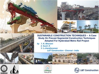
- 1. SUSTAINABLE CONSTRUCTION TECHNIQUES – A Case Study On Precast Segmental Construction Techniques Adopted For Hyderabad Metro Rail Project by 1. K. Bhavani 2. Sunil. K 3. L.chandravanan L&T Construction - Chennai - India TISI-2015
- 2. CONTENTS
- 3. WHY MRTS? Benefits • 1/5th energy per passenger km • Eco Friendly • Less road space(2.4m) • 3-4 lakhs passenger per hour • Reduce transport problem • Large area • Many railway crossings • Less frequency MMTS • Wide roads • Less passenger flow BRTS MRTSDis-advantage • Congestion on roads at the time of construction • Cost factor • Environmental impact Cost - Factor • By integrate metros with others systems considering - volume, structure, availability of space & resources for traffic and transportation. Traffic Congestion • Construction Techniques.MRTS – Sustainable Transport system during operation. During Construction ----?
- 4. HYDERABAD METRO - BRIEF Corridor -1 Corridor -2 Corridor -3 Interchange • VIADUCT: 71.16 KM • STATIONS: 66 NOS • DEPOT: 3 NOS ROB
- 5. SELECTION OF TYPE OF METRO RAIL- ELEVATED VIADUCT UNDER- GROUND RAIL High cost (2-3 times) Maintenance & HVAC High carbon footprint Security concern Deccan plateau – Underground rocks
- 6. COMPLEXITY IN CONSTRUCTION - ELEVATED METRO Traffic / Junctions –Least disturbance to traffic Heritage / Important structures Existing Utility Existing Railway Crossing (ROB) Paucity of space Existing bridges / Structures Utilityidentificationthrough trenching Miyapur S R Nagar Bharat Nagar Metro Station (~150m) Erragadda Metro station (~600m)
- 7. CONSTRAINS – CONSTRUCTION METHODOLOGY Sustainable Construction Methodology Minimum Disturbance to public Dismantling to existing structure Quality of Construction Reduced execution time Overall Economy
- 8. Span Alignment with 128m Curvature Corridor R≥600m % / No’s R <600 & ≥ 300m % / No’s R<300& ≥ 120m % / No’s C-1 89.4% / 744 No’s 6.5% / 54 No’s 4.1% / 34No’s C-2 86.8% / 353 No’s 5.5% / 22 No’s 7.7% / 31 No’s C-3 91.13% / 697 No’s 4.3% / 33 No’s 4.57% / 35 No’s MINIMUM DISTURBANCE TO PUBLIC AND EXISTING STRUCTURE Foundation • 90% Open Foundation • Reduced machinery Substructure • Single Pier • Portal Pier & L-Pier to avoid encroachment in road Superstructure • Box Girder • Viaduct-2.1m Height • Station-1.8m Height • 37m to 45m Span- 2.85m Height Proposed Alignment - MGBS to SalarJung Museum Revised Alignment - MGBS to SalarJung Museum Alignment - Curvature Pier Alignment for Curved Span
- 9. Cast segments are a major advantage of segmental construction Casting yard brings Factory controlled production techniques Effiency Quality control reducing overall construction time. Two methods of segment casting are available: Long line casting Short line casting QUALITY CONSTRUCTION- PRECASTING YARD Casting Yard Casting Yard Name Segment Cast Scope No. Segment Cast Nos. 1 Uppal 14000 6236 2 Qutubullahpur 14000 3735 Total 28000 9971 Casting Stacking Transportation
- 10. • 28,000 No’s of segments – 2 precast yards of 64.5 acres and 46.2 acres respectively • Asia’s second largest precast yard (second to Dubai metro) PRECAST YARD-FEATURES
- 11. Pier head Segment Casting Casting of Running Segment Match Casting of Segment Match Casting of Curved Segment Stacking of segment QUALITY CONSTRUCTION- SEGMENT CASTING & STACKING
- 12. SEGMENTAL CONSTRUCTION - planning of USLG for stations (Cycle time :2days/span) Box girder segments can be cast & stacked parallel to foundation and pier fast progress minimum disturbance curved alignment suitable for varying span lengths flexibility Construction cost 2 7 15 32 50 34 45 51 67 58 70 63 73 86 75 70 68 43 44 48 0 20 40 60 80 100 Dec'12 Jan'13 Feb'13 Mar'13 Apr'13 May'13 Jun'13 Jul'13 Aug'13 Sep'13 Oct'13 Nov'13 Dec'13 Jan'14 Feb'14 Mar'14 Apr'14 May'14 Jun'14 Jul'14 Month wise Span Erection Spans Erected
- 13. CHALLENGES – SEGMENTAL CONSTRUCTION Various Junctions/ Crossing Existing flyovers Rail crossing 67% of viaduct in curves 10% of viaduct with 128m R Pier height varying form 8m to 25m Construction duration Transportation of precast segment Challenges in segment erection
- 14. SUPERSTRUCTURE TYPE COMPARISON FOR VARIOUS METRO PROJECT – STATION SPANS More than 50% cast insitu- eliminated. Concourse level & plat form level Precast element. Cycle time was reduced.Formwork for Slab/Beams Completed view Formwork for columns/piers Erection of Viaduct platform level & Concourse - Erection Completed view Typical Cast In-situ Construction of Station Spans
- 15. Construction Elevated stations Erragada Station - ErectionJNTU Station – Platform Erection Concourse Level Platform Erection Uppal Station
- 16. Viaduct Erection Span by span Over slung LG (up to 128mR -31m span) Hinged LG Movable Winch LG Under slung LG Balanced Cantilever / Cantilever Under slung LG ROB erection (39m+65m+39m) Bridge Builder Continuous span Over slung LG Pocket track Loop line Flexibility to feed segment form erected span Segment Feeding using crane Station Viaduct (13-17m span) Special spans (37m-45m span) CONSTRUCTION METHODOLOGY - SEGMENTAL BOX ROB erection 128m R spans (39.5m+65m+32.5m)
- 17. SUPERSTRUCTURE TYPE COMPARISON FOR VARIOUS METRO PROJECT Description DMRC BMRC CMRL HMRL Concrete in Cum 165 160 151 145 Steel in MT 32 25.6 22 20 Pre-stressing steel in MT 5.8 5.6 5.0 4.65 Project Delhi Metro CC-17 Package Delhi Metro CC-28 Package Hyderabad MetroDescription Viaduct length 5.45 km 5.72 km 72 km Stations 3 No's 5 No's 66 No's Total spans 199 No's 223 No's 2700 No's Segmental spans 187 No's 198 No's 2680 No's I-Girder spans 27 No's 25 No's - Cast insitu spans - 8 No's 20 No's Minimum Radius of Curvature 250m 250m 128m Maximum segmental span length 37m 37m 45m I-girder Deck slab Typical Cross Section of Pocket track Box girder Insitu joint Typical Cross Section of Pocket track used in HMRP More than 95% spans are segmental spans. Special spans – Pocket track, loop line & service line are with box girder
- 18. THANK YOU … !
- 20. Capability of Hinged Launching Girder Erection of 34m span with a curvature of 250m. Erection of span ranging from 19m to 31m with a curvature of 128m • Less disturbance to traffic • Within Barrication width
- 21. 31m straight span External ground support 31m span in 152m horizontal radius - CMRL Advantage Of Introduction Of Hinge
- 22. Features 34m span erection in 250 m Radius of Curvature 31m span erection in 128m Radius of curvature No counter weight Segment can be picked from ground/completed deck LAUNCHING GIRDER WITH MOVABLE WINCH Typical Span Erection of Movable Winch LG over Flyover • Less disturbance to traffic • Feeding from erected deck
- 23. Capability of Underslung Launching Girder Erection of Special Spans (37m-45m). supported on the Trestles Cycle time – 15 days /span Typical Elevation of Under slung LG for 45m Span. Cycle time – Cast insitu span 45 days/span
- 24. Capability of Underslung Launching Girder Erection of station span (13.4m & 17m). supported on the Pier bracket stressed along with the station pier during erection and launching. Cycle time – 2 days /span • Reduce station completion time
- 25. Construction Elevated stations Erragada Station - ErectionJNTU Station – Platform Erection Concourse Level Platform Erection Uppal Station
- 28. BALANCED CANTILEVER/CANTILEVER– BRIDGE BUILDER New Market Metro station (~1000m) Malakpet Metro Station (~100m) Miyapur L B Nagar
- 29. BALANCED CANTILEVER/CANTILEVER– BRIDGE BUILDER
- 30. CONTINOUS SPAN – POCKET TRACK Pocket Track with Box Girder Erection Sequence of Pocket Track Girders
- 31. CONTINOUS SPAN – LOOP LINE Completed View of Loop line (Nagole Depot) Erection of Loop line (Nagole Depot) View of Loop line (Miyapur Depot)