PPT on execution of 680 m long tunnel ensuring safety of the adjoining rail tunnel with controlled blasting and monitoring in maoist affected zone of HDN route of SE Rly.
•Download as PPTX, PDF•
5 likes•1,546 views

The said paper by Rajesh Prasad Executive Director RVNL has been published in IPWE international seminar held on 23/24-02-2018. The power point presentation nicely explains about how the technical challenges and administrative challenges addressed in completion of the tunnel while constructing a tunnel by the side of a railway tunnel with train operation in place and the entire area is affected by LWE activities.

Recommended
More Related Content
What's hot
What's hot (20)
Similar to PPT on execution of 680 m long tunnel ensuring safety of the adjoining rail tunnel with controlled blasting and monitoring in maoist affected zone of HDN route of SE Rly.
Similar to PPT on execution of 680 m long tunnel ensuring safety of the adjoining rail tunnel with controlled blasting and monitoring in maoist affected zone of HDN route of SE Rly. (20)
More from Rajesh Prasad
More from Rajesh Prasad (20)
Recently uploaded
Recently uploaded (20)
PPT on execution of 680 m long tunnel ensuring safety of the adjoining rail tunnel with controlled blasting and monitoring in maoist affected zone of HDN route of SE Rly.
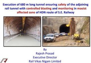
- 1. Execution of 680 m long tunnel ensuring safety of the adjoining rail tunnel with controlled blasting and monitoring in maoist affected zone of HDN route of S.E. Railway By Rajesh Prasad Executive Director Rail Vikas Nigam Limited
- 2. 680 m long tunnel execution. Monitoring of Vibration and Peak particle velocity in the adjoining tunnel. Execution in LWE area. GOELKERA – MONOHARPUR 3RD LINE Length 27.5 Km Phase-I (Posoita to Manoharpur) 11.6 KM Phase –I Commissioned on 04.05.2016 Phase-II (Goelkera to Posoita) 15.9 KM SCOPE RVNL Kolkata PIU is Implementing Agency M/s Unity-Triveni-BCPL (JV) are main Contractor. Central Institute of Mining & Fuel Research (CIMFR) Roorkee - DDC (Cost Rs. 80 Lakh) M/s SNC-Lavalin - PMC. (Cost Rs. 2.7 Crores) AGENCIES INVOLVED TECHNICAL CHALLENGE 3rd Line tunnel very close to the existing tunnel (c/c 31 m) ADMINISTRATIVE CHALLENGE LWE affected area.
- 3. FEATURES IN TUNNEL EXECUTION Curves in Tunnel alignment : 305m , straight with two curves of 3° in approach. Gradient - 1 in 100 Size and Shape of Tunnel: Modified Horse Shoe shaped Excavation Height – 8.041m. & Width – 7.365m. Excavating by heading and benching method Controlled blasting technique Ventilation shaft Steel rib support in portal and weak rock area Steel fibre reinforced shotcrete (SFRS) Rock bolt Concrete Backfilling LED lighting Monitoring system (to ensure safety of the adjoining tunnel) for the first time in IR
- 4. General complete cycle of tunnel excavation by drill and blast Drilling Survey Bolt Scale Dislodged Ventilate Blasting Loading
- 5. ROCK BLASTING Desirable Effects Unwanted Effects • Breaking the rock mass into desired shapes & sizes. • Displacing the broken rock • High Production/Pull • Ground Vibration • Air-blast • Flyrock • Over-Breakage • Back break • Damage to Rock Mass • Cost escalation • Increased cycle time
- 6. Rock strata encountered during execution tunnel PHYLLITE ROCK (Crack at 71º angle) QUARTZITE ROCK CARBONACEOUS SHALE
- 7. Tunnel excavation by Blasting • The blast designs with MCD (Maximum Charged density) of 14.0kg. • Controlled blasting has been done under guidance and direction of DDC i.e CIMFR. • Heading & benching method due to poor rock condition where stand up time is not very high. • Controlled blasting technique for the excavation of tunnel, trolley refuge, ventilation shaft.
- 8. • Tunnel heading portion is approx. 26 Sq.m. • Heading excavation is carried out by drilling (38 mm hole dia) with loading of emulsion explosive of dia 32mm and blasting with a maximum pull 1.8m. • Forepoles have been provided at immediate roof with the support of Steel Ribs. • Water seepage control - necessary arrangement of pumping of water. • Depending upon Rock mass stand-up time, immediate support of 100 mm thick reinforced shotcrete (SFRS) is being done by wet shotcrete machine. • Approx. 12 nos to 14 nos of Rock bolting (3 m length) @ 1.5m c / c in staggered way are provided. • After rock bolts erection, steel ribs of ISMB 200 are placed @ 0.6m c / c with 3.15 mm thick steel lagging before concrete back filling . • Cement grouting is done between back fill concrete and rock surface area . • Perforated PVC pipes are provided for weep holes at a spacing of 3.0 m interval in staggered way to take care of surface seepage . Heading Excavation
- 9. • Area of tunnel benching portion is approx. 25 Sq.m. • Benching excavation is done when the heading face of tunnel is about 14 m to 15 m away. • Excavation of benching part is also carried out through drilling and blasting method with a maximum pull of 1.8 m by using controlled blasting as per blasting design. • After the benching, the side wall supports are fixed on wall beam of ISMB 200. • 100mm thickness of SFRS(Steel fibre reinforce shotcrete) is sprayed before erecting Rock bolts. • Minimum 4 to 6 nos. of rock bolts are provided below spring level (benching portion) of the spacing between rock surface and steel ribs and back filled with M20 Grade concrete by using concrete pump. • Cement grouting is done before placing perforated PVC weep holes. Benching
- 10. Explosive: The latest generation emulsion explosive (power gel of ORICA make having 25 mm dia ,200 mm long and 125 gm by weight ) with 80-90% strength for blasting is used . The explosive is adequately sensitive, powerful and safe. For initiation of non-electric detonators (also termed as shock tube initiation system) of long delay is used. Afterwards Electric detonators with long delay series (excel series) is being used in underground tunnel blasting. 1.8 m deep blast hole is generally filled with 60% of emulsion explosive and remaining 40% length is filled by mud stick. LOADING OF EXPLOSIVE
- 11. Electronic Detonator The sequence of delay blasting by choosing 1 to 12 delay series of LDD (Long Delayed Detonator). The placement of LDD’s in heading is shown below. By this, blastings were done in sequences and during each blasting amplitude of shock waves was reduced to keep it within permissible limit for safety of nearby existing tunnel. Cross section of ED
- 12. Fixing of Electronic Detonator (LDD) for Blasting
- 13. VENTILATION SHAFT A ventilation shaft (2.0 m dia) circular in shape at the centre of the tunnel, i.e. at ch. 6300m has been provided. The shaft is around 35m deep from exposed surface of mountain to feed fresh air inside tunnel as well as natural lighting to some extent.
- 14. STEEL RIBS Specification of Steel Rib Support at Portal Area : Type of Steel Rib : ISHB 200 Weight per meter : 0.366 kN Cross-Section Area : 47.54 cm2 Spacing of rib : 100 cm at both the ends of tunnel Plain Shotcrete : M20 Steel rib supports have generally been used for the portal zone and inside the tunnel due to poor rock condition, except 160 m in patches where the rock support has been given by shotcreting only. ISHM 200 steel rib supports has been used. At back portion of steel rib & between the rock surface, the gap has been filled up by normal concrete so that full arch action could be generated for stability of tunnel.
- 15. STEEL RIBS
- 16. Specification of Shotcrete in the Tunnel Steel Fibre Reinforced Shortcrete (SFRS) of standard mix was used with 28 days UCS (Uniaxial Crushing Strength) of 50 Mpa and good bonding with the rock surface.
- 18. SLOPE PROTECTION BY FIXING WIREMESH SLOPE PROTECTION BY FIXING ROCK BOLT SHOTCRETE AT APPROACHES
- 19. Rock Bolt Specification of Rock Bolt in the Tunnel : Length : 3.0 m Diameter : 25mm tor steel Base Plate Size : 15 cm x 15 cm Thickness of Base Plate : 12mm Pullout Capacity of bolt : More than or equal to 15 tones fully grouted Spacing : Staggered systematic 1.5m centre to centre
- 20. Monitoring System • Controlled blasting under guidance of DDC. • Monitoring system for measuring vibration in the existing tunnel during blasting of 3rd line. • Seismograph equipment was installed in near by existing tunnel wall during every blasting to record the blasting amplitude and frequency of shock wave.
- 21. Inducespolarityofsignal Longitudinal geophone (L) Vertical geophone (V) Transverse geophone (T) The arrows indicate positive and negative ground motion represented by waveforms TIME + + + - - - + T + V + L - - - Event Standard Transducer Ground Vibrations V= Vertical T= Transverse L=Longitudinal Microphone Air Pressure Monitoring Device Limiting/Safe Value PPV= 10mm/sec. Noise = 146 dB
- 23. The summary of blast vibration and Fast Fourier Transform Analysis (FFT) PPV = 4.572 mm/s< 10mm/sec. Noise = 106.0 dB < 146 dB
- 24. Administrative Challenge STATUS OF LAW AND ORDER CONDITION AS REFLECTION IN NEWS PAPER (Dec. 2017) पश्चिम स िंहभूम में िाईबा ा के पोड़ाहाट जिंगल के ोनुवा थाना के कु दाबुरु गािंव के पा नक् सलयों ने िार ट्रैक्टर और एक जे ीबी मशीन में आग लगा दी. आज ोमवार दोपहर एक बजे के करीब नक् सलयों ने के नाल के ननमााण में ठेका किं पनी के काम लगे इन भारी वाहनों व मशीन में आग लगाई. घटना की जानकारी समलने के बाद िाईबा ा ए पी अनीश गुप्ता और ऑपरेशन असभयान ए पी मनीष रमन िाईबा ा े घटना स्थल पर पहुिंिे. दोनों पुसल अधिकाररयों ने घटना स्थल पर पहुिंि जािंि की और पा के लोगों े पूछताछ की. उन्हें घटना के बारे में कु छ महत्वपूणा जानकारी समली. िाईबा ा ए पी ने अनीश गुप्ता ने बताया कक भाकपा माओवादी के कमािंडर जीवन किं डुलना के दस्ते ने लेवी के सलए घटना को अिंजाम ददया है.घटना के बारे में बताया गया कक के नाल का ननमााण काया स्थल पर दोपहर एक बजे अिानक बड़ी िंख्या में हधथयारों े लै नक् ली पिंहुिे और वाहनों में आग लगा दी. Law and Order is still an issue.
- 25. Execution in LWE area • LWE – notified by Government of Jharkhand. • Past History – armed miscreants attacked tunnel camp. 19 nos. earth moving equipments, excavators, compactors etc. were burnt at the tunnel site. • It has happened twice in the section. • No Storage of explosive was permitted earlier. • Subsequently after meeting of CRB with Hon’ble CM Jharkhand on 06.12.2017, additional forces have been deployed and night working has also been permitted.
- 26. Work is being executed under 100% security cover of SAP posted by State Government of Jharkhand
- 27. MOVEMENT AND STORAGE OF EXPLOSIVE
- 29. • The technical challenge of ensuring safety of the existing tunnel has been met by using Vibration Monitoring System under the supervision of CSIR – CIMFR. • Technique is basically to have the delay introduced in sequence of blasting so that peak particle velocity of shock waves generated after blasting should not exceed the permissible limit in the existing nearby tunnel with train operation in place. • The administrative challenge of execution in maoist area has been resolved by having regular meetings with the senior officials of Government of Jharkhand and under the 100% protection of the force. • The tunnel work is likely to be completed by March, 2018 which was the most critical part of the project and the section is being commissioned in coming few months to benefit in de-congestion of the Howrah – Mumbai HDN route. • For the first time in Indian Railways, this monitoring system has been used to ensure safety of the existing tunnel while executing a new tunnel for double line or third line project. CONCLUSION
- 30. Team Work TEAMWORK divides the TASK and multiplies the SUCCESS
- 31. THANK YOU 31