1. RCP2 ROBO Cylinder
RCP2-GRM ROBO Cylinder 2-Finger Gripper Medium Slider Type 74mm Width Pulse Motor
■ Configuration: RCP2 GRM I 28P 1 14
Series Type Encoder Motor Deceleration Ratio Stroke Compatible Controllers Cable Length Option
28P: 28 □ size
Pulse motor
* See page Pre-35 for explanation of each code that makes up the configuration name.
(1) The maximum opening/closing speed indicates the operating speed on one side. The relative operating speed is twice this
value.
(2) The maximum gripping force is the sum of the gripping forces of both fingers, at a gripping point where there is no offset or
overhang distance. The work piece weight that can be actually moved depends on the friction coefficient between the
gripper fingers and the work piece, as well as on the shape of the work pieces. As a rough guide, a work piece's weight
should not exceed 1/10 to 1/20 of the gripping force.
(See page A-74 for details.)
(3) The rated acceleration while moving is 0.3G.
O I N
P
T
Notes on
Selection
Max. Gripping
Model Stroke
Force (N)
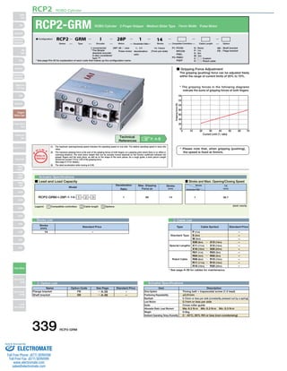
■ Gripping Force Adjustment
The gripping (pushing) force can be adjusted freely
within the range of current limits of 20% to 70%.
* The gripping forces in the following diagrams
indicate the sums of gripping forces of both fingers.
140
120
100
80
60
40
20
0
0 10 20
30 40 50 60 70
Current Limit (% ratio)
Gripping force (N)
Legend: 1 Compatible controllers 2 Cable length 3 Options (Unit: mm/s)
Stroke List 2 Cable List
Type Cable Symbol Standard Price
Standard Type
3 Option List Actuator Specifications
Item Description
Timing belt + trapezoidal screw (1.5 lead)
±0.01mm
0.15mm or less per side (constantly pressed out by a spring)
0.1mm or less per side
Cross roller guide
Ma: 6.3 N∙m Mb: 6.3 N∙m Mc: 8.3 N∙m
0.5kg
0~40°C, 85% RH or less (non-condensing)
Drive System
Positioning Repeatability
Backlash
Lost Motion
Guide
Allowable Static Load Moment
Weight
Ambient Operating Temp./Humidity
Actuator Specifications
■ Lead and Load Capacity ■ Stroke and Maxi. Opening/Closing Speed
Deceleration
Ratio
1 80
(mm)
RCP2-GRM-I-28P-1-14- 1 - 2 - 3 14
Stroke
Deceleration Ratio
14
(mm)
1 36.7
14 –
Special Lengths
Robot Cable
P (1m)
S (3m)
M (5m)
X06 (6m) ~ X10 (10m)
X11 (11m) ~ X15 (15m)
X16 (16m) ~ X20 (20m)
R01 (1m) ~ R03 (3m)
R04 (4m) ~ R05 (5m)
R06 (6m) ~ R10 (10m)
R11 (11m) ~ R15 (15m)
R16 (16m) ~ R20 (20m)
–
–
–
–
–
–
–
–
–
–
–
* See page A-39 for cables for maintenance.
Technical
References P. A-5
* Please note that, when gripping (pushing),
the speed is fixed at 5mm/s.
Stroke
(mm) Standard Price
Name Option Code See Page Standard Price
FB
SB
→ A-26
→ A-36
Flange bracket
Shaft bracket
–
–
I: Incremental
* The Simple
absolute encoder
is also considered
type "I".
P1: PCON
RPCON
PSEL
P3: PMEC
PSEP
N : None
P : 1m
S : 3m
M : 5m
X □□ : Custom
R □□ : Robot cable
SB : Shaft bracket
FB : Flage bracket
14: 14mm
(7mm per side)
1 : 1/1
deceleration
ratio
339 RCP2-GRM
Slider
Type
Mini
Standard
Controllers
Integrated
Rod
Type
Mini
Standard
Controllers
Integrated
Table/Arm
/Flat Type
Mini
Standard
Gripper/
Rotary Type
Linear Servo
Type
Cleanroom
Type
Splash-Proof
Controllers
PMEC
/AMEC
PSEP
/ASEP
ROBO
NET
ERC2
PCON
ACON
SCON
PSEL
ASEL
SSEL
XSEL
Pulse Motor
Servo Motor
(24V)
Servo Motor
(200V)
Linear
Servo Motor
Sold & Serviced By:
ELECTROMATE
Toll Free Phone (877) SERVO98
Toll Free Fax (877) SERV099
www.electromate.com
sales@electromate.com
2. RCP2 ROBO Cylinder
For Special Order P. A-9
2−ø3
4−M4 depth 8
(same with
opposite side)
2−3 +0.05 Depth 2.5
0
36
25
3 76
79
Note:
1 Compatible Controllers
The RCP2 series actuators can operate with the controllers below. Select the controller according to your usage.
24
4
2−M5 depth 8
Cable joint
connector*1
1.5 4−M4 depth 6
7 11.5
5
25
MAX 15
MIN 1
35
+0.03
0
5
74
3+0.05
28
24
36
0
12
0
−0.05
(same with opposite side)
Depth 2.5
ø3
+0.03
0 Depth 2.5
Depth 2.5 +0.03
0
(same with opposite side)
22
Secure at least 100
Dimensions
* The opening side of the slider is the home position.
*1 The motor-encoder cable is connected here. See page A-39 for details on cables.
The holes in the slider shown above, other
than tapped holes, are used to install the
slider onto the actuator. They cannot be
used as finger positioning holes.
Use the key slots to position the fingers.
Weight (kg) 0.5
Name External View Model Description Max. Positioning Points Input Voltage Power Supply Capacity Standard Price See Page
Solenoid Valve Type
PMEC–C–28PI–NP–2–1 Easy–to–use controller, even for beginners
3 points
AC100V
AC200V
See P481 – → P477
PSEP–C–28PI–NP–2–0
Operable with same signal as solenoid valve.
Supports both single and double solenoid
types.
No homing necessary with simple absolute
type.
DC24V 2A max.
–
→ P487
Splash–Proof
Solenoid Valve Type
PSEP–CW–28PI–NP–2–0 –
Positioner Type PCON–C–28PI–NP–2–0
Positioning is possible for up to 512 points 512 points
–
→ P525
Safety–Compliant
Positioner Type
PCON–CG–28PI–NP–2–0 –
Pulse Train Input Type
(Differential Line Driver)
PCON–PL–28PI–NP–2–0
Pulse train input type with
differential line driver support
(−)
–
Pulse Train Input Type
(Open Collector)
PCON–PO–28PI–NP–2–0
Pulse train input type with
open collector support
–
Serial
Communication Type
PCON–SE–28PI–N–0–0 Dedicated to serial communication 64 points –
Field Network Type RPCON–28P Dedicated to field network 768 points – → P503
Program Control
Type
PSEL–C–1–28PI–NP–2–0
Programmed operation is possible
Operation is possible on up to 2 axes
1500 points – → P557
* This is for the single-axis PSEL.
* 1 is a placeholder for the power supply voltage (1: 100V, 2: 100~240V).
RCP2-GRM 340
Slider
Type
Mini
Standard
Controllers
Integrated
Rod
Type
Mini
Standard
Controllers
Integrated
Table/Arm
/Flat Type
Mini
Standard
Gripper/
Rotary Type
Linear Servo
Type
Cleanroom
Type
Splash-Proof
Controllers
PMEC
/AMEC
PSEP
/ASEP
ROBO
NET
ERC2
PCON
ACON
SCON
PSEL
ASEL
SSEL
XSEL
Pulse Motor
Servo Motor
(24V)
Servo Motor
(200V)
Linear
Servo Motor
Sold & Serviced By:
ELECTROMATE
Toll Free Phone (877) SERVO98
Toll Free Fax (877) SERV099
www.electromate.com
sales@electromate.com