This document provides installation and operating instructions for various Krohne magnetic inductive flowmeters, including the IFM 2100 F, IFM 4100 F, IFM 5100 F, and IFM 9100 F models. It is divided into multiple parts that cover installation of the flowmeter and signal converter, programming and operation of the signal converter, special applications, functional checks, technical specifications, and other reference information. The instructions can be used to install the flowmeter in a pipeline, connect it to a signal converter, and have the system operational with just the information in Part A.
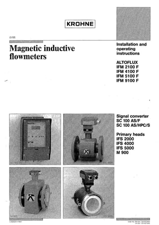
![& SeRarate-system fiowmeter as ordered
- SC 100 AS/F signal converter, field housing
- primary head with installation material according to the
• Installation and ORerating instructions with pl.:1#-out
condensed instructions for operation of the SC 100 AS/F
signal converter
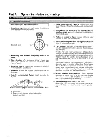
following table/list
- signal cable (field current cable not supplied, tobe
provided by customer)
• Certificate of system calibration data
• ReROrl on factory setting of the signal converter
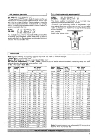
IFS 2000 and IFS 5000 Primary head
Primary head Supplied„. X=Standard O=Option Size of gaskets
Type Metersize Max. operating „.with „.with „.with grounding rings E „.wlo grounding rings
to."" pressure 1) centering stud bolts and gaskets but with gaskets 03 01, 02 + 03 in mm (inches) 3)
bar psig material
IFS 5000 :~]'!Jrr:.l2~Q1t{~S 4~q5f
ON 2.5, 4, 6, 10 40 580 2xrings 4xM12
ON 15 40 580 2xrings 4xM12
ON 25 40 580 2xrings 4xM12
ON 40 40 580 4xsleeves 4xM16
ON 50 40 580 4xsleeves 4xM16
ON 80 40 580 6xsleeves 8xM16
ON 100 16 230 6xsleeves 8xM16
25 360 6xsleeves 8xM20
IFS 2000 ON 150 16 230
/ /ON 200 10 145
ON250 10 145
IFS5000 ,.
.•. :ii":''~ec"''~'l
1/10, 1/8, 1/4, 3/8, 1/2" <20 <290 2xrings 4x1/2"
<40 <580 2xrings 4x1/2"
1" <20 <290 4xsleeves 4x1/2"
<40 <580 2xrings 4x5/8"
11/2" <20 <290 4xsleeves 4x1/2"
<40 <580 4xsleeves 4x3/4"
2" <20 <290 4xsleeves 4x5/8"
<40 <580 6xsleeves 8x5/8"
3" <20 <290 4xsleeves 4x5/8"
<40 <580 6xsleeves 8x3/4"
4" <20 <290 6xsleeves 8x5/8"
<25 <360 6xsleeves 8x3/4"
IFS 2000 6" <20 <290
1/1/8" <20 <290
10" <20 <290
1) With ANSI pipe flanges, the max. admissible operating pressure is
dependent on the product temperature
01
X
X
X
X
X
X
X
X
X
X
2) Gaskets 02 not supplied with flowmeter, tobe provided by customer!
01+02 and cable V da di
/ ~
01 are special 0-rings
01 are special 0-rings
0 X 46 (1.81) 26 (1.02)
0 X 62 (2.44) 39 (1.54)
0 X 74 (2.91) 51 (2.01)
0 X 106(4.17) 80 (3.15)
0 X 133 (5.24) 101 (3.98)
0 X 133 (5.24) 101 (3.98)
/ /
01 are special 0-rings
01 are special 0-rings
01 are special 0-rings
1/~
01 are special 0-rings
01 are special 0-rings
0 X 46 (1.81) 26 (1.02)
0 X 46 (1.81) 26 (1.02)
0 X 62 (2.44) 39 (1.54)
0 X 62 (2.44) 39 (1.54)
0 X 74 (2.91) 51 (2.01)
0 X 74 (2.91) 51 (2.01)
0 X 106 (4.17) 80 (3.15)
0 X 106 (4.17) 80 (3.15)
0 X 133 (5.24) 101 (3.98)
0 X 133 (5.24) 101 (3.98)
1//
01 are special 0-rings
01 are special 0-rings
01 are special 0-rings
3) da = outside diameter
di = inside diameter -
s = thickness of supplied gaskets
For arrangements of gaskets 01, 02 and 03 see "grounding diagrams" in Sect.1.2.3!
IFS 4000 and M 900 Primary heads
- lnterconnecting cables V, see grounding diagrams in Sect. 1.3.11
- Grounding.J:l.o.gs E (option), if ordered.
Supplied without installation material (stud bolts, gaskets),_to be customer supplied!
s
2)
2)
1.6 (0.06)
1.6 (0.06)
1.6 (0.06)
1.6 (0.06)
1.6 (0.06)
1.6 (0.06)
~)
2)
2)
2)
2)
1.6 (0.06)
1.6 (0.06)
1.6(0.06)
1.6 (0.06)
1.6(0.06)
1.6 (0.06)
1.6(0.06)
1.6 (0.06)
1.6 (0.06)
1.6(0.06)
2)
2)
2)
3](https://image.slidesharecdn.com/dok-150713074349-lva1-app6892/85/Dok-3-320.jpg)
![/ 1.3.1 Neoprnne and hard-rnbber liners
Note temperature limits
e Storage: - 20 to + 60 °C (- 4 to + 140 °F),
keep immobile
• Transport: - 5 to + 50 °C (+ 23 to + 122 °F)
• Process: Neoprene - 20 to + 60 °C (- 4 to + 140 °F)
Hard rubber - 20 to + 90 °C (- 4to+194 °F)
[Temperatures below - 5 °C (+ 23 °F) are only permiss-
ible if the pipe run is supported an both sides oftheflow-
meter, and providing there is only slight vibration and no
water hammer in the pipe.]
Gaskets are necessary for hard-rubber liners, e.g. Neoprene
or soft-rubber gaskets.
Max. torques: see Sect. 1.3.10, Column B
/ 1.3.2 PTFE liner
lnstall to avoid an excessive vacuum condition at the meter.
The PTFE liner is formed around the ends of the flanges,
do not remove or damage.
The flanges are factory-fitted with special protection covers.
Do not remove these until just before installation. Replace by
pieces of smooth sheetmetal [0.3 to 0.6 mm (0.012" to 0.024")
thick] when fitting the flowmeter between the pipe flanges (to
be removed after installation).
Attached protective rings can optionally be supplied, in
which case the above-mentioned sheet metal pieces are not
required. These protective rings can simultaneously be used
as grounding rings, see Sect. 1.3.7.
Max. torques: see Sect. 1.3.10, Column A.
/ 1.3.3 lrethane liner
lmportant for IFS 4000 primary head with irethane liner,
> 12 mm I > 0.47" thick:
The flange connections are !arger than the diameter of the
measuring tube! Use pipe flanges according to the following
tables.
Meter size ON in mm Meter size in inches
Measuring Flanges Measuring
tube tube
ON 350 ON 400 14"
ON 400, 450 ON 500 16", 18"
ON 500, 550 ON 600 20", 22"
ON 600, 650 ON 700 24", 26"
ON 700, 750 ON 800 28", 30"
ON 800, 850 ON 900 32", 34"
ON 900, 950 ON 1000 36'', 38"
ON 1000 ON 1200 40"
Max. torques (according to size of flanges!):
see Sect. 1.3.10, Column B
l 1.3.4 M 900 with sanitary connections
Versions
Flanges
16"
20"
24"
28"
32"
36"
40"
48"
e Sanitary pipe union to DIN 11851, ON 10 to 125
e Clamp connection, measuring tube 1" to 4"
Dimensions
Refer to Section 10.6.3
Cleaning the measuring tube
by CIP (cleaning in place) using various chemicals, acids,
alkalis, steam or water up to 140°C (284°F).
Installation
To prevent damage to the PTFE liner, the factory-supplied
rubber gaskets must be fitted without fail.
Grounding, refer to Section 1.3.11.
10
J 1.3.5 M 900 Hj with heating jacket
8 M 900 HJ primary heads with heating jacket are available
for ON 10 to 100 or 3/s" to 4" meter sizes (for dimensions
see Sect. 10.6.3).
e The two connecting flanges for the heating jacket are
designed to DIN 2501, ON 15, PN 40 or to ANSI, 1f2",
150 lbs.
e Max. operating pressure of heating medium:
10 bar /150 psig.
e The maximum permissible temperature of the heating
medium, in liquid or vapor state, is governed bythe insula-
tion class of the field coils (E up to 120°C / 248° F, H up to
180° C / 356 ° F) and the liner used for the measuring tube.
Refer to Sect. 10.5 for max. permissible operating data.
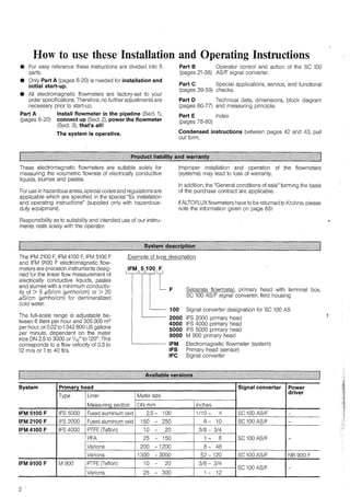
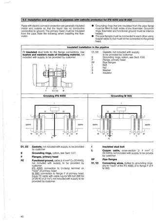
1.3.6 Pipelines with cathodic protection
For installation and grounding, refer to Sect. 6.5.
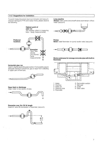
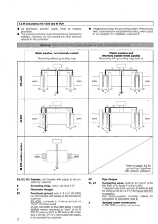
1.3.7 Grounding rings I Protective rings
8 Required in conjunction with plastic or internally coated
pipes.
e Grounding rings form a conductive connection with (he
fluid. ·
e Material CrNi steel 1.4571 or SS 316 Ti-AIS!, others on
request.
8 For grounding and connection of the grounding rings,
refer to Sect. 1.3.11.
1
2
3
Grounding ring No. 1,
3 mm/ 0.12" thick.
Grounding/protective
ring No. 2
for primary heads with
PTFE liner, fitted to the
flanges, 3 mm I 0.12" thick.
Grounding/protective
ring No. 3
with cylindi-ical neck,
to protect
the liner of the flowmeter
particularly at the
inlet edge in conjunction
with abrasive fluids.
- Length 30 mm for
ON 10 to 300 or
3/s" to 12".
- Length 100 mm for
2:: ON 350 or ;::::: 14".](https://image.slidesharecdn.com/dok-150713074349-lva1-app6892/85/Dok-10-320.jpg)
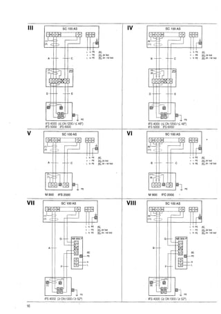
![f:l:l~~·!lll1~1~111f~1lll~lllllllll!ll.!·:lllllll.l:lll!.=l!l1.:l:l!l:::lil.!:::I
0 Electrical connection in conformity with VDE 0100
"Regulations governing heavy-current installations with rated voltages up to
1000 V" or equivalent national standard. Refer to connection diagrarns,
Seel. 2.5, for power connection to signal converter (and power driver, if pro-
vided).
e Do not cross or loop the cables in the terminal boxes of the primary head,
signal converter and power driver, if supplied. Use separate PG or NPT
screwed conduit entries for each cable~
O Special regulations apply to installation in hazardous areas. Referto Seel. 6.1
and special "Ex" installation instructions.
O On normal customer orders, the GK (primary constant) of the signal converter
is factory-setto match that ofthe primary head with which it is ordered. The GK
is engraved on the primary head nameplate and also shown on the converter
nameplate. These instruments should be installed together, otherwise
the converter will need to be reset (see Seel. 4.6 and 8.2, Fct. 1.04, 1.05 and
4.07).
fäi@l§.i.it~iliU~ifüii~fümli@itIIHIIlHHittIIItIIt11lt1IHl
e Do not expose signal converter (or power driver) and switch gear cubicle(s)
with installed units to direct sunlight. lnstall a sunshade, if necessary.
e Do not expose to intense vibration.
e Ensure adequate cooling of SC 100 AS/F unit(s) when installed in switchgear
cubicle(s), e.g. use heat exchangers.
• lnstall signal converter as close as possible to the primary head.
e Use factory-supplied standard signal cable A (type DS), standard length 10 m
(30 ft). For langer lengths and bootstrap signal cable 8 (type 8TS), refer to
Sect. 2.5.2 and 2.5.3.
e Always use the bootstrap signal cable 8 (type 8TS) for IFS 5000 primary
heads, DN 2.5 -15 OM' - %"), and in conjunction with contaminated fluids
having a tendency to form electrically insulating deposits.
!liliii::mi~MmiM~::;::@~'=«lifl1ftllitifl:::i[fü1Iiti1l
e Noteinformation given in Sect. 2.1!
• Note the information given on the instrument
nameplates on the primary head, signal converter
(voltage, frequency)!
e Power supply 24/42 Volt AC and 24 Volt DC,
functional extra-low voltage with protective separa-
tion (PELV) to VDE 0100, Part 410, or equivalent
national standards.
0 Power supplyforthe primary head via the signal con-
verter (or power driver, if applicable).
e Connection diagrams refer to Section 2.6.
e Line resistance for 24 V DC and 24/42 V AC
max. internal resistance Rmax of voltage supply
(transformer or DC voltage source and cable)
24 Volt DC / 24 Volt AC: Rmax 24 s 1 ohm
42 Volt AC: Rmax 42 s 2 ohms
max. length Lmax of power cable
Lmax = 28 X A (Rmax-R;)
A Cross-section of power cable in mm2
copper wire.
Rmax Interna! resistance of voltage supply
Rmax 24 or Rmax 42, see above
R; Interna! resistance of transformer or
DC voltage source
Example:
42 V AC / A = 1.5 mm2
/ R; = 0.2 ohm !
Rmax 42 = 2 ohms
Lmax = [28 x 1.5 (2-0.2)] = 75.6 m
75.6 m X 3.3 j!_ ::::: 250 fl
m
•.
Connection of several signal converters to 1 transformer
(n = number of converters)
Separate power cable: R; increases by factor "n" (R; xn)
Common power cable: Lmax decreases by factor "n"
(Lma/n)
!llliMHfli'-!llliiiI:'-i!ilMii#.r:li!i~J.illE~5,lIIf1IIl1ltlII11Hl1HIIfü111Il11I1Hll11tIIl1tllittitlt1Il11I111III1Hf1ttll
2.4.1 Abbreviations used and important information to Sect. 2.4
A Signal cable A (type OS) with double shielding; for max. length (Lmaxl see Diagram: cuNes A1 and A2
8 Signal cable 8 (type 8TS) with triple shielding; for max. length (Lmaxl see Diagram: cuNes 81, 82, 83 and 84
C Field power supply cable; for minimum cross-section (AF) and length see Table
D High-temperature silicone cable, 3 x 1.5 mm2
Cu / 3 x AWG 14, with single shielding, max. 5 m / 16 ft length
E High-temperature silicone cable, 2x1.5 mm2
Cu/ 2 x AWG 14, max. 5 m / 16 ft length
F Field power supply cable, connection between IFS 4000 primary head (ON ;;::: 1300 / ;;::: 52") and power driver;
see Table for minimum cross-section (AF) and max. length
G Gable connecting power driver and signal converter, min. cross-section 2 x 0.5 mm2 Cu / 2 x 20 AWG,
max. length 300 m (1000 ft)
AF Cross-section of field power supply cables C and F in mm2
(AWG) Cu, see Tables
L Length of cable
x Electric conductivity
ZD lntermediate connection box, required in conjunction with cables D and Efor IFS 5000 and IFS 4000 primary heads where process tem pera-
tures exceed 150°C (302°F)
• Determining the maximum permissible distance between primary head and signal converter
1. The length of signal cableA or Bis dependenton the electric conductivityx ofthe liquid product, and also on the type and meter size
of the primary head; see Table and Diagram "length of signal cable".
2. The length offield power supply cables C and Fis determined bythe cable cross-section AF; see Tables "field power supply cable C
and F".
3. The shortest cable length obtained either according to Point 1 or Point 2, is the maximum permissible distance between primary
head and signal converter!
e Special regulations apply to hazardous-area operation; refer to Sect. 6.1 and special "Ex" installation instructions.
• Always use the bootstrap signal cable B (type 8TS) for IFS 5000 primary heads, DN 2.5to15 (1
'1o"to 1
12") andin conjunction with contami-
nated fluids having a tendency to form electrically insulating deposits.
13](https://image.slidesharecdn.com/dok-150713074349-lva1-app6892/85/Dok-13-320.jpg)
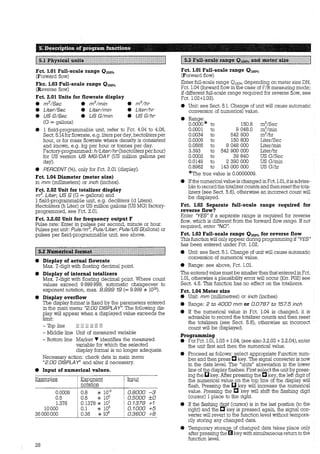
![[:?:~~!!l§iiii~fIIItIIIIIIIIIIIItII!IIIItIIIIIIIIfIIIIfIIIIIIIIIIIft!tIIflftIIIIIIIttillIIIIIIfII:IIlIIIIII!
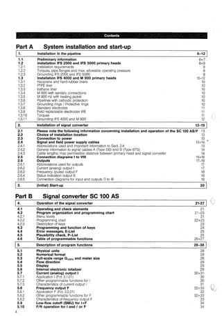
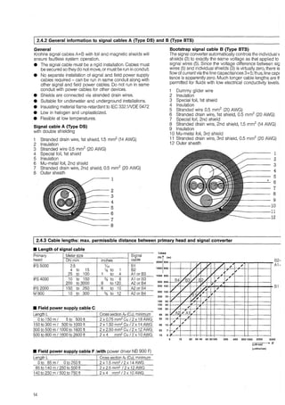
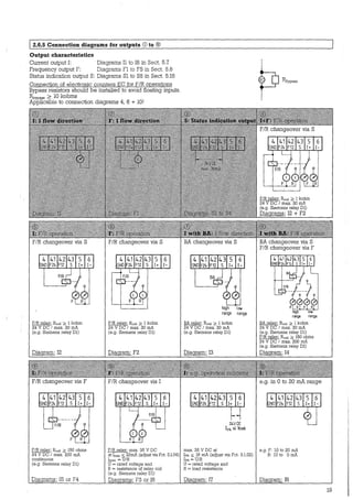
J 2.6.1 Abbreviations used for outputs
Abbreviation Stands for Programming
via Fct.No. ..........
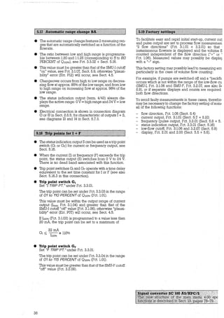
BA Automatie range change 3.3.01 + 3.3.02
EC Electronic counter -
EMC Electro-mechanical counter -
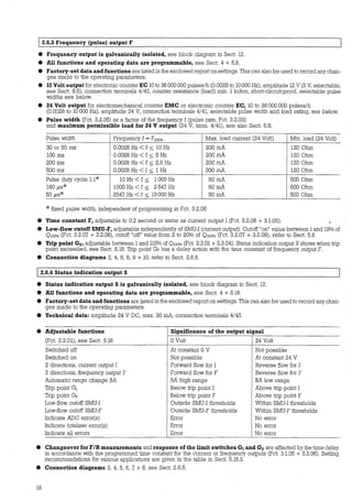
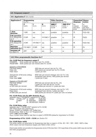
F Frequency (pulse) output 3.2.01 et seq.
F100% Pulses for O = 100% flowrate or 3.2.02 + 3.2.03
pulse value 3.2.02 + 3.2.04
Fmax Pulses at O higher than 100% flow -
(max. 115% of F10o%)
GF Trip point for frequency output 3.3.01 + 3.3.04
G1 Trip point for current output 3.3.01 + 3.3.03
1 Current (analog) output 3.1.01 et seq.
Io% Current at O = 0% flow 3.1.02
1100% Current at O = 100% flow 3.1.03
lrnax Current at O = over 100% flow 3.1.04
Oo% 0% flowrate -
0100% Full-scale range, 100% flowrate F:l.01 / R:l.02 + 1.03
Ornax Max. flow, O greater than 100%, -
corresponding to lmax + Fmax
s Status indication output 3.3.01 et seq.
SMU Low-flow cutoff for 1 + F 1:3.1.06 / F:3.2.07
SMU-1 Low-flow cutoff 1/ on value 3.1.07
off value 3.1.08
SMU-F Low-flow cutoff F / on value 3.2.08
off value 3.2.09
F/R Forward/reverse flow -
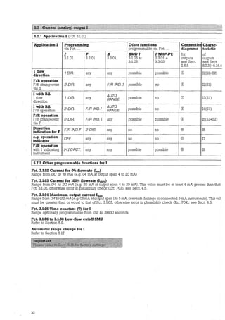
J 2.6.2 Current (analog) output 1
e Current output is galvanically isolated, see block diagram in Sect. 12.
• All functions and operating data are programmable, see Sect. 4 + 5.7.
Description
see Sect. „„„„„„••„.
5.17
5.8
5.8
5.8
5.8
5.8
5.8
5.18
5.18
5.7
5.7
5.7
5.7
5.3 (5.7 + 5.8)
5.3 (5.7 + 5.8)
5.3 (5.7 + 5.8)
5.16
„
5.9
5.9
5.9
5.9
5.9
5.10
• Factory-set data and functions are listed in the enclosed report on settings. This can also be used to record any
changes made to the operating parameters.
• Max. load at terminals 5/6 for hooo,,u (Fct. 3.1.03):
max. load in kohms =
20V
(e.g. 1 kohm for Iioo% = 20 mA)
1100% [mA]
• Time constant 1, adjustable between 0.2 and 3600 seconds (Fct. 3.1.05), refer to Sect. 5.7.
e Automatie range change BA, ratio 1:20 to 1:1.25 (corresponding to 5 to 80% of 0100%), adjustable in 1% increments
(Fct. 3.3.01+3.3.02), see Sect. 5.17. Changeover occurs from high to low range at approx. 85% of the low range, and from
low to high range at approx. 98% of the low range. Operative range displayed by status indication output S.
e Low-flow cutoffSMU-1, adjustable independently ofSMU-F (frequency output). Cutoff "on" value between 1and 19% of
Owo% (Fct. 3.1.06 + 3.1.07), cutoff "off" value from 2 to 20% of 0100% (Fct. 3.1.06 + 3.1.08), refer to Sect. 5.9.
e Trip point Gh adjustable between 1 and 110% of 0100% (Fct. 3.3.01 + 3.3.03). Status indication output S shows when trip
point exceeded, refer to Sect. 5.18. Trip point G1 has a delayed action equal to the time constant of current output I.
e Connection diagrams 1, 4, 5, 7, 8, 9, 10, 11 + 12, refer to Sect. 2.6.5.
17](https://image.slidesharecdn.com/dok-150713074349-lva1-app6892/85/Dok-17-320.jpg)
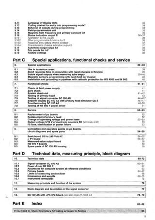
![Part B Signal converter SC 100 AS
This Section 4 is repeated in the form of pull-out condensed operating instructions between pages 42 and 43.
!M~!t§i#i'.fü~$fi~it~fil@i.)~QS.M#ilf1fllIIIIIIflf1lIIlIIffIItttlfiffffffIIIlIIIIffällt1ItIIIItittitltifU
J--1~----+•
~JL_Q_b__&.__,
MAGNET (OPTION)
-, r o 1
i: 0 J. 1
rn=:l/hr
1 1 1
SC100AS]
+----?--+--<2
iL~
~
Q ENTER Ü QENTERÜ
1 ill]::::::[IIJ 1
t:m::~Ij::[IIJ
u
ALTERN.
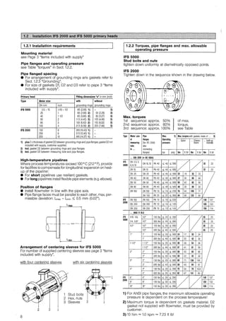
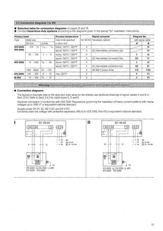
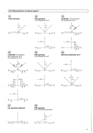
1 4.2.1 Menu levels
NORMAL
IF-TEST
CD Display, lst line
® Display, 2nd line
® Display, 3rd line,
cursor symbols described below:
Q Actual flowrate
+
Status indication output S
active (= 24 V)
Totalizer (Forward flow)
Totalizer (Reverse flow)
Surn totalizer (+ and - )
Low-flow cutoff SMU for
current and/or frequency
output (I/F) "in function"
@ Keys for programming the signal converter, refer to
Sect. 4.3 for function of keys.
@ Magnetic sensors (option) to program the converterby
means of a hand-held bar magnet without having to
open the housing, refer to Sect. 6.3. Function ofsensor'8
same as keys @. Hold the bar rnagnet by the black rub-
ber cap. Apply blue end of the magnet (north pole) to
the glass pane above the magnetic sensors. Sensor
response acknowledged by symbols appearing in lst
line of display.
® Plug connector
(J) Plug-in jurnper positi.ons to check field power supply,
refer to Sect. 7. 1.
The program for the signal converter consists of 5 levels. The Fct.No. in the lst line (bottorn line) of the display will identify
the menu level during prograrnming. ·
Measuring 1 Actual display
mode level
1 Err. E 01- E 16 1 Err. P 01 - P 14 1 1 TOT. RESET
Reset
totalizer
Mainmenu
level
Submenu
level
Function
level
Data level
Measuring mode Error in Error in
(see Sect. 4.3)
1
program plausibility check
(see Sect. 4.4) (see Sect. 4.5)
1 1
r----------~ 1
1 1--------------------~
1 1
T T
Fct. 1.00 Fct. 2.00 Fct. 3.00
Display Outputs
1---------------i Fct. 4.00
Special fct.
Fct. 1.01-
1.07
Data changes acc. to Table in Sect. 4.6 possible only on this level!
21](https://image.slidesharecdn.com/dok-150713074349-lva1-app6892/85/Dok-21-320.jpg)
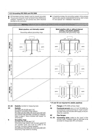
![1 4.2.2 Programming chart Table of functions, see Sect. 4.6
Fct. 4.02: with coding (YESJ
Measurin:g mode
Entry into tprogramming '------1•-----l]•----11•,.___ ___,
mode, see Sect.
5.12
Fct. 1.00
FLOW DATA
Fct. 1.00
FLOW DATA
Fct. 4.02: without coding (NOJ
Fct. 2.00
DISPLAY
Fct. 2.00
DISPLAY
Fct. 3.00
OUTPUTS
Fct. 3.1.00
CUR.DUTP. I
r------;
,_ _______.
Fct. 3.1.00
GUR. OUTP. I
Fct. 3.00
OUTPUTS
Err.E01-E16 _____ ._ _____ ~
-..... Error in meas. mode, see E-List, Sect. 4.4 C!ear
-..... error
Display next error, message tErr. E02-E16 ifmore
··~ ,„ r_·- Terminate error output
1
Fct. 3.2.00
FRE OUTP. F
Fct. 3.2.01 -
3.2.09
Fct. 3:2.01 -
3.2.09
Fct. 3.2.00
FRE OUTP. F
Fct. 3.3.00
/ND. OUTP. S
Fct. 3.3.01 -
3.3.04
Fct. 3.3.00
!NO. OUTP. S
Measuring mode 1-------~-----___,
Plausibility-
check
,_______, Err. P01 - P14 Err. P02 - P14 1--------
Error detected by plau- '. Display next
sibility check, see P-List error, if more
Sect. 4.5 than one
Reset totalizer, see Sect. 5.6
Measuring mode 1---~---L oa--------1Measuring mode
22](https://image.slidesharecdn.com/dok-150713074349-lva1-app6892/85/Dok-22-320.jpg)
![Fct. 1.00
FLOW DATA
1Measuring mode 1
1
4.2.3 Description of keys
O 1 Measuring mode level
Enter programming mode
Display errors
Clear error messages
See left for function of keys
Important
applies to all menu levels
1. Continuously pressing C or [] keys will
cause their function to be continuously
repeated (auto-repeat function).
2. If no keystrokes made within approx.
180 sec, signal converter reverts autom.
to meas. mode without accepting any
changed data into meas. prog. (time-out
function). Exception: if at start of
"----+------------------1 programming Err. E04, E05 and/or E14
established, see Sect. 4.4.
Fct. 4.00
SPEC. FCT.
Fct. 4.01 -
4.10
Fct. 4.01 -
4.10
Fct. 4.00
SPEC. FCT.
..-- Terminate error output and revert
to main menu level,
lst·main menu displayed
Fct. 1.00
FLOW DATA
Correct faulty fanction(s)
and data
f) 1 Main menu level
[] Select main menu
C Enter main menu displayed
[j [j [j Revert to measuring mode level, see @
01 Suhmenu level
[] Select menu
C Enter submenu displayed
[j Revert to main menu level, see 0
0 1 Function level
[] Select function
C Enter function displayed,
continue as under 0
"Data level"
[j Return to main menu or
submenu level
01 Submenu level
[j Revert to main menu level
[] Select submenu
C Enter submenu displayed
@ 1 Main menu level
Data/Units
[] Select next
proposal
C Return to
Fct. level,
retain
previous
data/units
Numerical values
Increase flashing digit
(cursor) by 1
Shift flashing digit
1 place to right.
Note: if in last
position, system
reverts to Fct.
level, last numerical
value retained!
Return to Fct. level, store new data
temporarily. Note: display
"Err. 0000 < MIN" or "9999 > MAX"
means num. value too low or too high.
Press any key to display permissible min.
or max. value, then enter correct
numerical value.
} see 0
[j [j [j Return to measuring mode level, any changed data accepted into
measuring program
[] Select main menu
C Enter main menu displayed } see f)
01 Measuring mode level
- Plausibility check }
see left for function of keys
- Reset totalizer
01 Main menu level
Function of keys same as under f)
23](https://image.slidesharecdn.com/dok-150713074349-lva1-app6892/85/Dok-23-320.jpg)
![fä@~!:ri~if.imiii.:!:ii~Ut~ifMfäi{!!l:~H~~!III!IIIIIIlIIII!IIIIIIIIIIII!IIIIIIIIJ!II!lIEtimIIIIIItIIII!tI:ItIIIIl
After powering, the signal converter enters the normal measuring mode.
1 Proarammina sfart
- -Key Display Cornments
1st line l2nd linel
ccr::u:u::;rn (ENTER 1, 2, 3, 4, 51 with
} Coding, dependent on programming of
or Fct. 4.02 (YES or NO), refer to Sect. 4.6 + 5.12
rn without
Err. 01„.16 Error(s) in measuring mode, see E-List, Sect. 4.4
appears only, if one or more errors have occurred during measuring Operation
a Err. 02.„16 display next error, if more than one
m terminale error display
Fct. 1.00 !FLOW DATAJ Main menu level, lst main menu displayed, continued as described below
Function of keys in main menu, submenu, functional and data levels, see Sect 4.6
Key Main menu level Submenu level Data level
Functional level Data/Units Numerical values
a Select Select Select next lncrease flashing digit
.main menu submenu or function proposal (cursor) by 1
c Ent.er displayed Enter displayed Return to functional Shift flashing digit (cursor)
mammenu submenu or function level, previous data/units retained 1 place to the right.
Note: If in last position, system
will revert to functional level,
last numerical value retained
rn - - - Revert to main menu Revert to functional level, store new data,
or submenu level units or numerical values temporarily. *
1·
*Flashing display Err. 0000<MIN or Err. 9999>MAX= numerical value too low or too high. Press any key to obtain dis-
play of permissible minimum or maximum value, then enter correct numerical value.
Important
1. Continuously pressing the C or [] key will cause the function of these keys to be continuously repeated (autorepeat
function).
2. If no keystrokes are made for approx. 180 seconds, the signal converter will automatically revert to the measuring mode
without accepting any changed data into the measuring program (time-out function). Exception: if at start of program-
ming errors Err. E04, E05 and/or E14 are established, see Sect. 4.4.
Newly ente:red data will only be accepted into the measuring program ifthe programming mode is terminated
by following the procedure below.
P:rogramming end
Key Display Comments
1st line l2nd linel
1, 2 or 3 x[ai Fct. 1.00„.4.00 Select main menu level
mmm Revert to measuring mode level
Plausibility check, lasts approx. 5 seconds
/
Actua/ measured value No error in plausibility check, any changed data accepted into measuring
program, actual measured value displayed (measuring mode level)
Err. P01...14 Error(s) in plausibility check, see P-List, Sect. 4.5
a Err. P02„.14 Display next error, if more than one
m Fct. 1.00 !FLOW DATAJ Terminate error display and revert to main menu level, Ist main menu displayed,
select faulty function(s) and correct data, see Sect. 4.6
Totalize:r :reset
Key Display l2nd linel Comments
cma IENTER 1, 21 Measuring mode not interrupted
ramm !TOT. RESETJ Totalizer reset
Actua/ measured value Measuring mode level, actual measured value displayed
Clearing e:r:ror messages in measuring mode, see Sect. 4.4
Key Display
1st !ine l2nd linel
IENTER 1,2,3,4,51
or
Err. E01„.E16
Fct. 1.00 !FLOW DATAJ
Actua/ measured value
24
Comments
with 1
without
Goding, dependent on prograrnming of Fct. 4.02
(YES or NO), refer to Sect. 4.6 + 5.12
Error messages (not with Err. E04, E05 and/or E14)
Main menu level
Measuring mode level, actual measured value displayed](https://image.slidesharecdn.com/dok-150713074349-lva1-app6892/85/Dok-24-320.jpg)
![E-List Description of error Rectify instrument fault Error output in measuring mode via
E:rror messages an.d/or - Display (Fct. 2.04) and/or
clear error message - Status indication output (Fct. 3.3.01)
dependent on programming
Display NO ADC TOT.
lst line* 2nd line MESS. ERROR ERRDR
Err. E01 UNE /NT. Power failure since D - - yes
last programming reset totalizer(s) if necessary
Note: no counting during
power failure
Err. E02 TOTAL/ZER Counts lost or totalizer D - - yes
overflow
Note: totalizer was reset!
Err. E03 DISPLAY Numerical overflow of display Check data Fct. 2.00 - - -
Display lst line: ------------------
Display 3rd line: note T Marker!
Err. E04 EEPROM 1 Data error in EEPROM 1 Check instrument parameters * * * * **
(parameters) 0
Err. E05 CAL. DATA Calibration data lost Recalibrate signal converter, ** * * **
please consult factory
Err. E06 EEPROM 2 Data error in EEPROM 2 (totalizer) D - - yes
Note: totalizer deviation possible reset totalizer(s) if necessary
Err. E07 RAM Check-sum error in RAM 0 - - -
Err. EOB ROM Check-sum error in ROM 0 - - -
Err. E09 AOC ADC value overranged or 0 - yes -
! .
ADC defective
Err. E12 FREQ.OUTP. F Frequency output overranged D - - -
If necess„ check data, Fct. 3.2.00
Err. E13 CUR.OUTP. I Current output overranged D - - -
If necess„ check data, Fct. 3.1.00
Err. E14 EE1 EE2 Current calibration values Terminale programming mode ** ** * *
EPPROM 1+2 are different (press IJ key 4x), values
(occurs only when pc board changed)
corrected automatically
Err. E16 FUSE FS fuse for power failure Fit new F5 fuse, yes*** yes*** yes***
identification defective see Sect. 8.5
* When errors are displayed during the measuring mode, "a numera/" and "Err." will appear in the lst line.
The numeral gives the nurnber of momentarily occurring errors !hat are displayed alternately with the actual measured value.
* * No output in measuring mode! With these errors, the signal converter is automatically in the programming mode.
* * * No output via status indication output (Fct. 3.3.01)
D
0
Invoke and then terminale programming mode.
Keystrokes: 2 XC / 2 X[] / 2 XI] and 4 X IJ or 1 X IJ and 4 XI] (dependent on programming in Fct. 4.02)
Invoke and then terminate programming mode.
Keystrokes: 2 X c I 2 X a I 2 X ra and 4 X IJ or 1 X ra and 4 X ra (dependent on prograrnming in Fct. 4.02)
Consult factory if these errors occur several times in succession.
Err. P.. Text Description
Err. P01 V RANGE Velocity v outside possible range (0.3 to 12 .m/s or 1 to 40 ft/s)
FULL SCALE (Fct. 1.01) <>DIAMETER (Fct. 1.04)
Err. P02 REV. SCALE REV. SCALE (Fct. 1.03) > FULL SCALE (Fct. 1.01)
Err. P03 !RANGE I 0 PCT. (Fct. 3.1.02) > j 100 PCT. (Fct. 3.1.03) or difference < 4 mA
Err. P04 IMAXmA I MAX mA (Fct. 3.1.04) < I 100 PCT. (Fct. 3.1.03)
Err. P05 ICUTOFF I: CUTOFF ON (Fct. 3.1.07);;:::: CUTOFF OFF (Fct. 3.1.08)
Err. P06 FCUTOFF F: CUTOFF ON (Fct. 3.2.08) ;;:::: CUTOFF OFF (Fct. 3.2.09)
Err. P09 F> 10 KHZ Frequency for Q100% > 10 kHz
Err. P10 PULS W!OTH Max. pulse width exceeded (see Fct. 3.2.05)
ALL
ERROR
yes
yes
yes
* *
* *
yes
yes
yes
yes
yes
yes
**
yes
Err. P12 RNG./CUTOFF 2nd range of automatic range change (see Fct. 3.3.02) :S; I CUTOFF ON (see Fct. 3.1.07)
Err. P14 I TRIP PT. I TRIP PT. (Fc:t. 3.3.03) outside range of current output (see Fct. 3.1.04)
25](https://image.slidesharecdn.com/dok-150713074349-lva1-app6892/85/Dok-25-320.jpg)
![Fct. No. Text Description and input
3.00 OUTPUTS Main menu 3.00 Outputs
.... -·· ..,„..,. „_...... ..., .;;a""""""l:'"'..........„ .1,,..1,..1.,1,.l.!-'U.L
3.1.00 GUR. OUTP. I Submenu 3.1.00
1.00 FLOW DATA Main menu 1.00 Measurement Current output (I), Seel. 5.7
1.01 FULL SCALE Full-scale range for
flowrate Q1oo%
Unit: select from !ist (Seel. 5.1)
Range: (Seel. 5.3):
0.0034 to 542 900 m3
Ihr or
0.8962 to 143400000 US Glmin
After selecting unit, call numerical
value with C key, lst digjt flashes
1.02 REV. SCALE Different range for reverse
flow? NO or YES
3.1.01 FUNCT/ON I Function, current output (l)
• OFF(= switched off)
e F/R /NO. F(=F/Rindication forF)
• 1 DIR. (= 1 flow direction)
• I < I 0 PCT (=Forward/Reverse
flow, e.g. in 0-20 mA range:
F=l0-20 mA, R=l0-0 mA)
• 2 DIR.(= forward/reverse
flow, F/R measurement)
3.1.02 IO PCT. Current for 0% flow Clo%)
1.03 VALUE Full-scale range for reverse
flow (appears only if YES entered
under Fct. 1.02)
Unit: select from !ist (Seel. 5.1)
Range: 00 to 16 mA
3.1.03 1100 PCT. Current for 100% flow,
Full-scale range (I100%)
Range: 04 to 20 mA
Range: (Sect. 5.3):
0.0034 to 542900 m3
1hr or
(Value at least 4 mA greater
than !hat of Fct. 3.1.02)
0.8962 to 143400000 US Glmin
Value must not be greater
than that of Fct. 1.01
After selectinr;;_ unit ca// numerica/
valua with C key, lst digit flashes
3.1.04 IMAXmA Adjustment of max. output
current Cimaxl
Range: 04 to 22mA
(Value must be greater than/equal
to that of Fct. 3.1.03)
1.04 DIAMETER Meter size 3.1.05 T-CONST. I Time constant, current output
Unit in mm or inch Range: 0.2 to 3600 Sec.
Range: 2 to 4000 mm or
0.0787 to 157.5 inch
After selecting unit, call numerical
3.1.06 L.F.CUTOFFI Low-flow cutoff (SMU) for
current output?
NO or YES (Sect. 5.9)
value· with C key, lst digit flashes 3.1.07 CUTOFFON Cutoff "on" value SMU-I
1.05 GK VALUE Primary constant GK
(see.primary head nameplate)
Range: 0.5 to 14
(appears only if YES entered
under Fct.No. 3.1.06)
Range: 01 to 19 PERCENT
1.06 FLOW DIR. Define direction of forward
(normal) flow
Enter acc. to direction of arrow
{ + or - Jon primary head
1.07 ZERO CALIB. Zero calibration (Sect. 7.2)
Csm out only at "O" flow and when
measurina tube comnl. filled with fluid
3.1.08 CUTOFFOFF Cutoff "off'' value SMU-I
(appears only if YES entered
under Fct. 3.1.06)
Range: 02 to 20 PERCENT
(Value must be greater
than !hat of Fct. 3.1.07)
3.2.00 FRE. OUTP. F Submenu. 3.2.00
1) Inquiry: CALIB. NO or YES Frequency output (F), Sect. 5.8
2) If YES: calibration (duration 45 sec)
with zero display in PERCENT of 0 100%
3) Inquiry: STORE NO or YES
2.00· DISPLAY .·' Main menu 2.00 Display
3.2.01 FUNCT/ON F Function, frequency output (F)
• OFF(= switched off)
e FIR !ND. I (= FIR indication for !)
e 1 DIR.(= 1 flow direction)
2.01 OISP. FLOW Unit for flowrate display
• m
3
/Sec • m
3
Imin • m
3
/h
• 2 DIR.(= forward/reverse
flow, F/R measurement)
• Liter/Sec • Liter/min • Liter/h 3.2.02 PULSOUTP. Unit, frequency output
e US G/Sec e US Glmine US Glh e PULSRATE (= input in pulses
e h Literlhr or US MG/DA Y per unit time)
(=hectoliters per hour, for US version e PULSE/UN/T (= input in pulses
US million gallons per day) factory per unit volume)
set, can be changed as required
via Fct. 4.04, 4.05+4.06 (Sect. 5.14)
e PERCENT
e NO DISPLAY
2.02 UNIT TOTAL. Unit for totalizer display
• m
3
• Liter • US G
3.2.03 PULSRATE Pulse rate for 100% flowrate
(appears only if PULSRATE
entered under Fct. 3.2.02)
Range:
2.778*10-3
to 10000 pulses/Sec
0.1667 to 600000 pulseslmin
• h Liter or US MG (hectoliters 10 to 36 000 000 pulseslhr
or US million gallons) see After selecting unit, call numerical
Fct.No. 2.01 {h LiterIhr or US G/DAY)
2.03 O/SP. TOTAL. Function of totalizer display
• + TOTAL. (= forward totalizer)
• - TOTAL. (= reverse totalizer)
• +/- TOTAL. (= forward and
reverse flow totalizers, altemating)
e SUM TOTAL. (= sum of + and
- totalizers)
e ALL TOTAL. (= sum, + and
- totalizers, altemating)
e NO O/SPLAY (= totalizer
switched on but no display)
e TOTAL. OFF(= totalizer
switched off)
value with C key, lst digjt flashes
3.2.04 PULSE/UN/T Pulse value
(appears only if PULSEIUNIT
entered under Fct. 3.2.02),
Unit in pulses per m3, Liter, US G
or unit of Fct. 4.04, 4.05 + 4.06
(Sect. 5.14) - Range:
0.0001 to 0.9999*109
pulses
[no input check but:
0100%* pulse value ::::;
36 000 000 pulses ~ 10 kHz]
After selecting unit, call numerical
value with C key, lst digjt flashes
2.04 ERRORMSG Which error messages to 3.2.05 PULS WIOTH Pulse width for frequencies ::::;10Hz
be displayed? (Seel. 4.4)
• 30mSec.
• 50mSec.
e NO MESSAGE • 100mSec. • 200mSec.
(= no error messages) • 500mSec.
e AOC ERROR (= only ADC
conversion errors)
e TOT ERROR
(= only errors of intemal totalizer)
e ALL ERROR (=all errors)
2.05 O/SP. TEST Carry out display test
Start with C key
3.2.06 T-CONST. F Time const. for frequency output
T< F> = 0.2 Sec.
T< F> = T< I >(=time constant
for F same as for I, Fct. 3.1.05)
3.2.07 L.F.CUTOFF F Low-flow cutoff (SMU) for
frequency output
NO or YES (Sect. 5.9)
26](https://image.slidesharecdn.com/dok-150713074349-lva1-app6892/85/Dok-26-320.jpg)
![Fct. No. Text Description and input Fct. No. Text Description and input
3.2.08 CUTOFFON Cutoff "on" value SMU-F 4.00 SPEC. FCT. Main menu 4.00
(appears only if YES entered Special functions
under Fct. 3.2.07)
Range: 01 to 19 PERCENT
4.01 LANGUAGE Language of display texts, Sect. 5.11
e GB/USA (= English)
3.2.09 CUTOFFOFF Cutoff "off'' value SMU-F • 0 (= German)
(appears only if YES entered e F (= French)
under Fct. 3.2.07) e SF (= Finnish)
Range: 02 to 20 PERCENT • others pendinq
(Value must be greater
than that of Fct. 3.2.08)
4.02 ENTRYCOOE Coding for entry into
programming mode? Sect. 5.12
3.3.00 /NO. OUTP. S Submenu 3.3.00 Status indication
output (S), Sect. 5.16
• NO = entry with 1:§1 key
• YES = entry with keys
3.3.01 FUNCTION S Funct. of status indication output
• OFF(= switched off,
0 V at term. 4/43)
• ON(= switched on,
24 V at term. 4/43, e.g. as
operational status indicator
e FIR /NO. I (= FIR indication
c c [][][§1 [§1
4.03 OUTP. HOLD Hold values of outputs
during programming?
NO or YES (Sect. 5.13)
4.04 UNITTEXT Text for field-programmable
unit, Sect. 5.14
for I), Sect. 5.10 A„.Z I a„.z / 0„.9 I _ (= space)
e F/R /NO. F (= F/R indication 4.05 FACT. QUANT. Conversion factor for
for F), Sect. 5.10
e AUTO. RANGE (= automatic
range change), Sect. 5.16
• I TRIP. PT. (= trip point I as %
quantity FM, Sect. 5.14
Factor FM= quantity l§er 1 m3
Range: 0.00001*10- to
9.99999*10+9
of 0100%• Fct. 3.3.03)
e F TRIP. PT. (= trip point F as %
of 0 100%, Fct. 3.3.04)
e L.F.CUTOFF I (= low-flow cutoff I),
Fct. 3.1.06
e L.F.CUTOFF F (= low-flow cutoff F)
Fct. 3.2.07
4.06 FACT. TIME Conversion factor for time FT
Sect. 5.14
Factor FT in seconds
Range: 0.00001*10-9
to
9.99999* 10+9
4.07 FIELO FREQ. Magnetic field frequency,
e AOC ERROR}
e TOT. ERROR s. E-List Sect. 4.4
e ALL ERROR
Sect. 5.15+8.2
• 116 • 1116 • 1132
4.08 NO/SE Noise rejection, Sect. 6.2 .,
3.3.02 AUTO. RANGE Automatie range change for e NO NO/SE
current output, see Sect. 5.17 e NO/SE
(appears only if AUTO. RANGE
enternd under Fct. 3.3.01)
4.09 REF. SEL. Selecting the reference voltage
Sect. 6.2
Range: 05 to 80 PERCENT of 0 100%, e AUTO. REF.
(Value must be greater than
SMU-1 cutoff "on" value, Fct. 3.1.07)
(= automatic rnfernnce)
e HIGH-FLOW
3.3.03 I TRIP PT. Trip point for current output, (= high flow range)
Sect. 5.18 (appears only if e MED1-FLOW
I TRIP PT. enternd underFct. 3.3.01) (= lst medium flow range)
Range: 001 to 110 PERCENTof 0 100%
(Value must be greater than
e ME02-FLOW
(= 2nd medium flow range)
SMU-1 cutoff "off" value, Fct. 3.1.08) e MED3-FLOW
3.3.04 F TRIP PT. Trip point for frequency output,
Sect. 5.18 (appears only if
F TRIP PT. entered under Fct 3.3.01)
(= 3rd medium flow range)
e LOWFLOW
(= low flow ranqe)
Range: 001 to 115 PERCENTof 0 100% 4.10 FIELD GUR. Input of field current
(Value must be grnater than
SMU-F cutoff "off" value, Fct. 3.2.09)
Range: 225.00 to 275.00 mA
(see sticker at term 7 + 8 on
"basic" pc board/with power driver
NB 900 F always ± 250 mA)
Must not be changed, Sect. 7.2 + 8.1!
27](https://image.slidesharecdn.com/dok-150713074349-lva1-app6892/85/Dok-27-320.jpg)
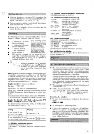
![e To avoid erroneous measurements at lowflowrates, the
S:rvfTJ SV'"Vitches the CUi--rent fu!d frequency outputs (I+F)
off. I goes to Io% (Fct. 3.1.02) and F to 0 Hz.
• If "NO"is entered underfunctions 3.1.06 +3.2.07, fixed
cutoff "on" and cutoff "off" values of 0.1 and 0.25%,
resp., of 0100% (full-scale range, see Fct. 1.01) act on the
outputs I + F.
• If "YES"is entered under functions 3.1.06 + 3.2.07, the
cutoff "on" and cutoff "off" values forI +F are separately
adjustable in the ranges specified below.
• The low-flow cutoff (SMU) can be indicated either for I
orfor F via the status indication output S(see Sect. 5.16).
Fct. 3.1.06 Low-flow cutoff (SMU) for I desired?
Enter NO or YES.
Fct. 3.1.07 Cutoff "on" value for SMU-I
(appears only if "YES" entered in Fct. 3.1.06)
Range: 01to19 PERCENTof 0 100% -
The low-flow cutoffdrives the current outputto lo% when the
flow decreases to the cutoff "on" value (see Fct. 3.1.02).
Fct. 3.1.08 Cutoff "ofr' value for SMU-I
(appears only if "YES" entered in Fct. 3.1.06)
Range: 02 to 20 PERCENTof 0 100%
This value must be greater than that of Fct. 3.1.07, other-
wise a "plausibility" error (Err. POS) will occur, see Sect. 4.5.
When the flow returns to the cutoff "off" value, the current
output returns to normal.
Fct. 3.2.07 Low-flow cutoff (SMU) for F desired?
Enter NO or YES:
Fct. 3.2.08 Cutoff "on" value for SMU-F
(appears only if "YES" entered in Fct. 3.2.07)
Range: 01to19 PERCENTof 0 100%
The low-flow cutoff drives the frequency output to 0 Hz
when the flow decreases to the cutoff "on" value.
Fct. 3.2.09 Cutoff "off" value for SMU-F
(appears only if "YES" entered in Fct. 3.2.07)
Range:: 02 to 20 PERCENTvon 0 100%
This value must be greater than that of Fct. 3.2.08, other-
wise a "plausibility" error (Err. P06) will occur, see Sect. 4.5.
When the flow returns to the cutoff "off" value, the fre-
quency output returns to normal.
!iil#J.mt.ml„ii~ii~ttiii~i~[m.@li#lfüfüJI1J11111t11tH~I
Electrical connection, characteristic and programming of
outputs, refer to Sect. 2.6, 5.7 + 5.8.
Fct. 1.06 Define direction of forward (normal) flow
(+ or -)
In the case of F/R operation, program the direction of the
forward flow with "+"or"-·:in accordance with the arrows
marked "+" and "-" on the primary head. Note that if the
flowmeter does not have a "+" and "-" on the primary head
the "+" direction is the direction the arrow is pointing.
Fct. 1.01 Full-scale setting for flowrate 0 1oo%
Program the full-scale range. Unit and range, see Sect. 5.1
+ 5.3.
Fct. 1.02 Separate range desired for reverse flow?
Enter "YES" only if the range required for reverse flow is
differentfrom the range for the normal (forward) flow. Ifnot,
enter "NO".
34
Fct. 1.03 Full-scale range for reverse flow
(appears only if "YES" entered in Fct. 1.02). This is used fo:
programming the full-scale range for reverse flow. Uni
and range, see Sect. 5.1 + 5.3. This value must not bE
greater than that of Fct. 1.01, otherwise "plausibility" erro:
(Err. P02) will occur, see Sect. 4.5.
A choice of languages for the display texts is offered ir
Fct. 4.01:
• GB/US English
• D Gerrnan
• F French
e SF Finnish
other languages pending.
11ii1111•1i11~~llillli~;lllllilllll1Bllljlll
• Enter NO or YES.
• If "NO" entered, there are 2 ways of entering the pro-
gramming möde:
1. by pressing the mkey only or
2. by pressing the C C [] [] 1]11]1 keys.
• If "YES" entered, the only way of entering the
programming mode is to press keys as follows:
ccaamm
tm.11j~!ii!Hiij~ifji!mimi~liHiiIIWfiim~iiIIIM
e Enter in Fct. 4.03 whether or not the outputs shall hold
the last values (before entry into the programming
mode).
• If "YES" entered: output values prior to entry into the
programming mode are retained duringprogramming.
After leaving the programming mode, the outputs go to
the values corresponding to the actual operating condi-
tions.
e If "NO" entered: the outputs go to the programmed
minimum values:
I to the value of Io% (see Fct. 3.1.02)
F to 0 V, consequently no pulses
S to 0 V.](https://image.slidesharecdn.com/dok-150713074349-lva1-app6892/85/Dok-34-320.jpg)
![An arbitrary volumetrie flow unit or, if density of the fluid
produet is consistent and knovvn, a unit of mass (weight)
ean be programmed in funetions 4.04 to 4.06. The unit
"h Literlhr" (heeto-liters per hour) is faetory-set unless
another special unit is speeified. US-version: "US
MG/DA Y" (US million gallons per day).
Fct. 4.04 Text for field-programmable unit
• Volumetrie (or mass) unit per unit time
• Text for volume (mass): 6 charaeters (places)
• Text for time: 3 characters (plaees)
9 The fraction bar "/" in the 7th plaee has a fixed position.
• Alpha charaeters A-Z and a-z, numbers 0-9 or blank
charaeter (J are seleetable for every plaee.
• Pressing the [] key will sequenee the alpha eharaeters
and numbers in the order given above.
• The C key shifts the eursor 1 plaee to the right.
• Text examples are given in the following Tables in
braekets (....../...).
Fct. 4.05 Conversion factor Quantity FM
Enter the faetor FM= quantity per 1 m3
.
Volumetrie unit Factor FM
Cubie meters (m 3) 1.0
Liters (Liter) 1000
Heeto-liters lhLiter) 10
Deei-liters (d Liter) 10000
Centi-liters (c Liter) 100000
Milli-liters (m Liter) 1000000
US gallons (US G) 264.172
US million
0.000264172gallons (US MG)
Imperial gallons
219.969(GB G)
Imperial mega-
0.000219969gallons (GB MG)
Cubie feet (Feet 3) 35,3146
Cubie inehes (inch 3) 61024.0
US barrels liquid 8.38364
US fluid ounees 33813.5
Fct. 4.06 Conversion factor Time FT
Enter the faetor Fr in seeonds.
Time unit Factor FT
[seconds]
Seeond (Sec) 1
Minute (min) 60
Hour (hr) 3600
Day (DAY) 86400
Year (YR)
31536000(.2. 365 days)
Fct. 1.05 GK value
Inpuit
1.00000± 0
1.00000 + 3
1.00000 + 1
1.00000 + 4
1.00000 + 5
1.00000 + 6
2.64172 + 2
2.64172 :-- 4
2.19969 + 2
2.19969 - 4
3.53146 + 1
6.10240+ 4
8.38364± 0
3.38135 + 4
Input
1.00000± 0
6.00000 + 1
3.60000 + 3
8.64000 + 4
3.15360 + 7
'J'he primfily eonstant GK is faetory-set. Range: 0.5 to 14,
dependent on primary head, see instrument nameplate.
Examples of volume per unit time
Desired Hecto-liters Deci-liters
units: per year per hour
Volumetrie
unit h Liter d Liter
in Fet. 4.04
Faetor FM 10 10000(see Table)
Input in
1.00000 + 1 1.00000 +4Fet. 4.05
Time unit
YR hr
in Fet. 4.04
Faetor Fr 31536000 3600
(see Table) (seconds) (seeonds)
Input in
3.15360 + 7 3.60000 +3Fet. 4.06
Examples of mass per unit time
Produet density Q = 1.2 g/em3
= 1.2 kg/Liter= eonstant
Mass of 1 m3 produet = 1200 kg = 2646 pounds
Desired Kilograms Pounds
unit: per minute per hour
Mass unit
kg lbs
in Fet. 4.04
Factor FM
1200 2646(see Table)
Input in
1.20000 + 3 2.646 + 3Fet. 4.05
Time unit
min hrin Fet. 4.04
Factor Fr 60 3600(see Table)
Input in
6.00000 + 1 3.60000 +3Fet. 4.06
Fct. 4.07 Magnetic field frequency
The magnetie field frequeney is factory-set to 116, 1116
or 1132 of the power frequeney, see signal eonverter
nameplate.
Data of Fct. 1.05 + 4.07 must not be changed! Exeeption: replaeement of prirn.ary head, see Seet. 8.2
35](https://image.slidesharecdn.com/dok-150713074349-lva1-app6892/85/Dok-35-320.jpg)
![Part C Special applications, functional checks and senice
6. Special applications
!fäi~j,tJfä~t#miw.Ji.tiii.iil~~~iJlitf@tltltI{Ifüillitft!
Altoflux electromagnetic flowmeters are certified to Euro-
pean standards and to Factory Mutual standards
(FM) as electrical appliances suitable for use in hazar-
dous areas.
Onlythe primaryheads are permitted tobe installed
in the hazardous area. The signal converter must always
be installed outside the hazardous area.
Allocation oftemperature class to temperature ofthe fluid,
meter size and material of the measuring tube liner is spe-
cified in the test certificate.
Since the intrinsically safe signal circuit is grounded under
field conditions via the fluid, equipotential bonding is
required in the entire hazardous area andin the cable run
ofthe mtrinsically safe signal circuit (inside and outside the
hazardous area).
Test certificate, certificate ofconformity and wiring
instructions are attached to the Installation and
Operating Instructions (applies only to hazardous-
duty equipment).
lli~~ll!ll.lllllrt1~11111illl~lilllillllilillill·:llllil:::
The signal converter is equipped with an intemal automa-
tic reference unit which ensures optimum adjustment to
the input signal from the primary head during changing
flowrates.
In the case of rapidly changing flowrates, e.g. batching
processes and where operation with reciprocating pumps
is involved, it may be necessary to influence or cut out this
automatic unit via Fct. 4.08 and 4.09.
With Fct. 4.08, the response time of the automatic unit is
decreased by up to 30%.
The automatic unit is switched off via Fct. 4.09. However,
this reduces the measuring accuracy of the signal con-
verter.
Since there are no hard and fast rules for applying Fct. 4.08
and 4.09, it is advisable to determine the optimum setting
as follows.
Always switch off the power source before connec-
ting and disconnecting cables!
• Connect an LED with series resistor (0.68 to 2 kohms) or
an oscilloscope to terminals 4 + 43 (digital voltmeters
are unsuitable).
• Program "ADC ERROR"in Fct. 3.3.01 (status indication
output).
• Start the flow.
• The optimum setting for the signal converter is found
when the LED does not turn off (remains lighted),
• If the LED tums off, even momentarily, reprogram the
signal converter in the following order until the LED
remains on (lighted).
Order Fct. 4.08 Fct. 4.09
lst NO/SE AUTO. REF.
2nd NO NO/SE HIGH FLOW
3rd NO NO/SE MED1-FLOW
4th NO NO/SE MED2-FLOW
5th NO NO/SE MED3-FLOW
6th NO NO/SE LOWFLOW
• Subsequently, reprogram Fct. 3.3.01 (status indication
output) according to its original application.
• If the above procedure does not lead to the desired
effect, please consult factory.
l'::~1~::1lllRlil~ll~~i:lllll!l~llit~:·111111i1iill1:llllililllllll
Output values can be stabilized to values as for "zero" flow
to prevent random output signals when the measuring tube
is empty orwhen the electrodes are notwetted in the event
the measuring tube is partially full.
This means:
Totalizer Display - does not accumulate random
counts
Current output - value of Io% (see Fct. 3.1.02)
Frequency output - 0 V(= no pulses)
Preconditions
• Electrical conductivity offluid ~ 200 µSlcm (µmholcm)
[~ 500 µSlcm (µmholcm) in conjunction with primary
head IFS 5000 (-Ex), DN::; 15 or:::;; 1/ 2"]
• Max. signal cable length 50 m (165 ft), for cable type DS
or BTS.
Changes on basic pc board
(see components drawing, Sect. 9.1)
• Insert two resistors Rx = 10 Mohms
• Insert soldering jumper Lx.
Additional change to programming
Program low-flow cutoff (SMU) for current output I and fre~
quency output F as follows (minirnum values):
Fct. 1 F Comments
3.1.06
YES YES Activate SMU
3.2.07
3.1.07
1 PERCENT 1 PERCENT Cut off "on" value
3.2.08
3.1.08
2 PERCENT 2 PERCENT Cut off "off" value
3.2.09
Note
The low-flow cutoff function does not affect the flowrate
display, Fct. 2.01: DISP. FLOW Therefore, depending
upon the resolution of this display, there may be a slight
positive or negative flowrate displayed during the period
the pipe is empty or the measuringtube electrodes are not
wetted.
lii:ll:lll.r.~l.lllf.lllllmllllllilil:ji!j:llililllliillllil:iill:l
• The signal converter can optionally be equipped with
magnetic sensors, see Sect. 4.1, Item 5.
e This allows programming of the signal converter by
means of a hand-held bar magnet. Function of sensors
without removing the front cover is the same as the cor-
responding keys. Sensor response is acknowledged
by symbols in the lst line of the display.
• Hold the bar magnet by the black rubber cap. Apply
blue end of the magnet (north pole) to the glass pane
above the magnetic sensors.
39
'1](https://image.slidesharecdn.com/dok-150713074349-lva1-app6892/85/Dok-39-320.jpg)
![Condensed lnstructions - SC 100 AS 0119s IKROHNE j
3K24E/A6 019521 Printed in Gennany Subject to change without notice. ° Copyright KROHNE-Messtechnik GmbH & Co.
[:j~iM~llfü8ii#ifüi!I~ii1tfJ1111fI1lfitff1f11Ilfilfill1t1HlHII1Il!Itttt!füilfl@1Hf1@[~f[llHf1Ittmm
After powering, the signal converter enters the normal measuring mode.
Key Display 1st line l2nd linel Comments
CCDD1111l (ENTER 1, 2, 3, 4, 5]
with 1 Coding, dependent on programrning of
or
a
D
Key
a
c
Err. 01...16
Err. 02... 16
Fct. 4.02 (YES or NCI';, refer to Seel. 4.6 +5.12
without
Error(s) in measuring mode, see E-List, Sect. 4.4
appears only, if one or more errors have occurred during measuring operation
display next error, if more than one
terminale error display
Fct. 1.00 lFLOW OATAJ Main menu level, lst main menu displayed, continued as described below
Main menu level
Select
mainmenu
Enter dIBplayed
mainmenu
Submenu level
Functional level
Select
submenu or function
Enter displayed
submenu or function
Revert to main menu
or submenu level
Data level
Data/Units
Select next
proposal
Return to functional
level, previous data/units retained
Numerical values
Increase flashing digit
(cursor) by 1
Shift flashing digit (cursor)
1 place to the right.
Note: If in last position, system
will revert to functional level,
last numerical value retained
Revert to functional level, store new data,
units or numerical values temporarily. *
*Flashing display Err. 0000< M/Nor Err. 9999> MAX=numerical yalue too low ortoohigh. Press anykeyto obtain dis-
play of perrnissible minimum or maximum value, then enter correct numerical value.
Important ·
1. Continuously pressing the C or D key will cause the function of these keys to be continuously repeated (autorepeat
function).
2. lfno keystrokes are made for approx. 180 seconds, the signal converter will automatically revert to the measuring mode
without accepting any changed data into the measuring program (time-out function). Exception: if at start of program-
ming errors Err. E04, E05 and/or E14 are established, see Sect. 4.4.
Newly entered data will only be accepted into the measuring program ifthe programming mode is terminated
by following the procedure below.
Key
1, 2 or 3 xi]
llllll
Key
CllD
ll ll ll
Key
ccaamm
o:r
Display 1st line l2nd linel
Fct. 1.00...4.00
Actua/ measured value
Err. P01...14
Err. P02...14
Fct. 1.00 lFLOW DATAJ
Display l2nd linel
lENTER 1, 21
lTOi. RESETJ
Actua/ measured value
Display 1st line l2nd Jinel
lENTER 1,2,3,4,51
Err. E01...E16
Fct. 1.00 lFLOW DATAJ
Actua/ measured value
Comments
Select main menu level
Revert to measuring mode level
Plausibility check, lasts approx. 5 seconds
lfo error in plausibility check, any changed data accepted into measuring
prograrn, actual measured value displayed (measuring mode level)
Error(s) in plausibility check, see P-List, Sect. 4.5
Display next error, if more than one
Terminate error display and revert to main menu level, lst main menu displayed,
select faulty function(s) and correct data, see Sect. 4.6
Comments
Measuring mode not interrupted
Totalizer reset
Measuring mode level, actual measured value displayed
Comments
with lwithout
Coding, dependent on programrning of Fct. 4.02
(YES or NCJ), refer to Sect. 4.6 + 5J2
Error messages (not with Err. E04, E05 and/or E14)
Main menu level
Measuring mode level, actual measured value displayed
A](https://image.slidesharecdn.com/dok-150713074349-lva1-app6892/85/Dok-43-320.jpg)
![Text
1.01 FULL SCALE
1.02 REV. SCALE
1.03 VALUE
1.04 DIAMETER
1.05 GKVALUE
1.06 FLOW DIR.
1.07 ZERO CALIB.
2.01 DISP. FLOW
2.02 UNITTOTAL.
2.03 DISP. TOTAL.
2.04 ERRORMSG
2.05 DISP. TEST
B
Desc::ription and input
:e'n .i>~!!~B:;.
Full-sc::ale range for
ßowrate 0100%
Unit: select from list (Sect. 5.1)
Range: (Sect. 5.3):
0.0034 ta 542900 m3
Ihr or
0.8962ta143400000 US G/min
After selecting unit. call numerical
value with C key. Ist diqit flashes
Different range for reverse
ßow? NO or YES
Full-sc::ale range for reverse
ßow (appears only if YES entered
under Fct. 1.02)
Unit: select from list (Sect. 5.1)
Range: (Sect. 5.3):
0.0034 ta 542900 m3
Ihr or
0.8962 ta 143400000 US G/min
Va/ue must not be greater
than that af Fct. 1.01
After se/ectjng unit ca// numerica/
value with C key. Ist diqit flashes
Meter size
Unit in mm or inch
Range: 2 ta 4000 mm or
0.0787 ta 157.5 inch
After selecting unit. call numerical
value with C key, Ist diqit flashes
Primary c::onstant GK
(see primary head nameplate)
Range: 0.5 ta 14
Deime direc::tion of forward
(normal) ßow
Enter acc. to direction of arrow
( + or - J on primary head
Zero c::alibration (Sect. 7.2)
Carry out only at "O" flow and when
measurin tube com 1. filled with fluid
1) Inquiry: CALIB. NO or YES
2) If YES: calibration (duration 45 sec)
with zero display in PERCENT of 0100%
3) Inquiry: STORE NO or YES
'"'II,
Unit for ßowrate display
• m3
/Sec • m
3
Imin • m
3
lh
• Liter/Sec • Liter/min • Literlh
e US G/Sec e US G/mine US Glh
e h LiterIhr or US MG/DA Y
(=hectoliters per hour, for US version
US million gallons per. day) factory
set, can be changed as required
via Fct. 4.04, 4.05+4.06 (Sect. 5.14)
e PERCENT
e NO DISPLAY
Unit for totalizer display
• m
3
• Liter • US G
• h Liter or US MG (hectoliters
or US million gallons) see
Fct.No. 2.01 (h LiterIhr or US G!DAY)
Func::tion of totalizer display
• + TOTAL. (= forward totalizer)
• - TOTAL. (= reverse totalizer)
e +/- TOTAL. (= forward and
reverse flow totalizers, altemating)
e SUM TOTAL. (= sum of + and
- totalizers)
e ALL TOTAL. (= sum, + and
- totalizers, altemating).
e NO D/SPLAY (= totalizer
switched on but no display)
e TOTAL. OFF(= totalizer
switched off)
Whic::h error messages to
be displayed?· (Sect. 4.4)
e NO MESSAGE
(= no error messages)
e ADC ERROR (= only ADC
conversion errors)
e TOT. ERROR
(= only errors of intemal totalizer)
e ALL ERROR (=all errors)
Carry out display test
Start with CJ key
3.1.01 FUNCTIONI
3.1.02 I 0 PCT.
3.1.03 1100 PCT.
3.1.04 IMAXmA
3.1.05 T-CONST. I
3.1.06 L.F.CUTOFFI
3.1.07 CUTOFFON
3.1.08 CUTOFFOFF
3.2.01 FUNCT/ON F
3.2.02 PULSOUTP.
3.2.03 PULSRATE
3.2.04 PULSE/UN/T
3.2.05 PULS WIDTH
3.2.06 T-CONST. F
3.2.07 L.F.CUTOFF F
Func::tion, c::urrent output (1)
e OFF (= switched off)
e FIR /NO. F(=F/RindicationforF)
• 1 DIR. (= 1 flow direction)
• I < I 0 PCT. (=Forward/Reverse
flow, e.g. in 0-20mA range:
F=l0-20 mA, R=l0-0 mA)
• 2 DIR. (= forward/reverse
flow, F/R measurement)
Current for 0% ßow CJoq.)
Range: 00 ta 16 mA
Current for 100% ßow,
Full-scale range CI100%)
Range: 04 ta 20 mA
(Value at least 4 mA greater
than that of Fct. 3.1.02)
Adjustment of max. output
c::urrent Cimax)
Range: 04 ta 22mA
(Value must be greater than/equal
to that of Fct. 3.1.03)
Time c::onstant, c::urrent output
Range: 0.2 ta 3600 Sec.
Low-ßow c::utoff (SMU) for
c::urrent output?
NO or YES (Sect. 5.9)
Cutoff "on" value SMU-I
(appears only if YES entered
under Fct.No. 3.1.06)
Range: 01 ta 19 PERCENT
Cutoff "off" value SMU-I
(appears only if YES entered
under Fct. 3.1.06)
Range: 02 ta 20 PERCENT
(Value must be greater
than that of Fct. 3.1.07)
Func::tion, frequenc::y output (F)
• OFF(= switched off) _
e FIR !NO. I (= FIR indication for I)
• 1 DIR. (= 1 flow direction)
• 2 DIR. (= forward/reverse
flow, F/R measurement)
Unit, frequenc::y output
e PULSRATE (= input in pulses
per unit time)
e PULSE/UNIT(= input in pulses
per unit volume)
Pulse rate for 100% ßowrate
(appears only if PULSRATE
entered under Fct. 3.2.02)
Range:
2.778*10-3
ta 10000 pulses/Sec
0.1667 ta 600 000 pu/ses/min
10 ta 36 000 000 pu/ses/hr
After selecting unit, call numerical
value with C key, lst diqit flashes
Pulse value
(appears only if PULSE/UN/T
entered under Fct. 3.2.02),
Unit in pulses per m3
, Liter, US G
or unit of Fct. 4.04, 4.05 + 4.06
(Sect. 5.14) - Range:
0.0001 ta 0.9999*1a9 pu/ses
[no input check but:
0100%* pulse value ::;
36 000 000 pulses ~ 10 kHz]
After selecting unit, call numerical
value with C key, Ist digit flashes
Pulse width for frequenc::ies ::;toHz
• 30mSec. • 50mSec.
• 1OOmSec. • 200mSec.
• 500mSec.
Time c::onst. for frequency output
T< F> = 0.2 Sec.
T< F> = T< I >(=time constant
for F same as for !, Fct. 3.1.05)
Low~flow c::utoff (SMU) for
frequenc::y output
NO or YES (Sect. 5.9)](https://image.slidesharecdn.com/dok-150713074349-lva1-app6892/85/Dok-44-320.jpg)
![Fct. No. Text
3.2.08 CUTOFFON
3.2.09 CUTOFF OFF
3.3.01 FUNCTION S
3.3.02 AUTO. RANGE
3.3.03 I TRIP PT.
3.3.04 F TRIP PT.
Description and input
Cutoff "on" value SMU-F
(appears only if YES entered
under Fct. 3.2.07)
Range: 01to19 PERCENT
Cutoff "off'' value SMU-F
(appears only if YES entered
under Fct. 3.2.07)
Range: 02 to 20 PERCENT
(Value must be greater
than that of Fct. 3.2.08)
Funct. of status indication output
• OFF(= switched off,
0 V at term. 4/43)
• ON(= switched on,
24 V at term. 4/43, e.g. as
operational status indicator
e FIR /NO. I (= FIR indication
for I), Sect. 5.10
e FIR /NO. F (= FIR indication
for F), Sect. 5.10
e AUTO. RANGE(= automatic
range change), Sect. 5.16
e I TRIP. PT. (= trip point I as %
of 0100%, Fct. 3.3.03)
e F TRIP. PT. (= trip point F as %
of 0100%, Fct. 3.3.04)
e L.F.CUTOFF I (= low-fl.ow cutoffI),
Fct. 3.1.06
e L.F.CUTOFF F (= low-flow cutoff F)
Fct. 3.2.07
e AOC ERROR}
e TOT. ERROR s. E-List Sect. 4.4
e ALL ERROR
Automatie range change for
current output, see Sect. 5.17
(appears only if AUTO. RANGE
entered under Fct. 3.3.01)
Range: 05 to 80 PERCENT of 0100%•
(Value must be greater than
SMU-I cutoff "on" value, Fct. 3.1.07)
Trip point for current output,
Sect. 5.18 (appears only if
I TRIP PT. entered under Fct. 3.3.01)
Range: 001to110 PERCENTof 0100%
(Value must be greater than
SMU-I cutoff "off" value, Fct. 3.1.08)
Trip point for frequency output,
Sect. 5.18 (appears only if
F TRIP PT. entered under Fct. 3.3.01)
Range: 001to115 PERCENTof010o%
(Value must be greater than
SMU-F cutoff "off" value, Fct. 3.2.09)
4.02 ENTRYCODE
4.03 OUTP. HOLD
4.04 UNITTEXT
4.05 FACT. QUANT.
4.06 FACT. TIME
4.07 FJELD FREQ.
4.08 NO/SE
4.09 REF. SEL.
4.10 FJELD GUR.
Coding for entry into
programming mode? Sect. 5.12
• NO = entry with fil key
• YES = entry with keys
CJ CJ [] IJ fil fil
Hold values of outputs
during programming?
NO or YES (Sect. 5.13)
Text for field-programmable
unit, Sect. 5.14
A„.Z I a„.z I 0„.9 / _ (= s ace)
Conversion factor for
quantity FM, Sect. 5.14
Factor FM= quantity ~er 1 m3
Range: 0.00001*1U to
9.99999*10+9
Conversion factor for time FT
Sect. 5.14
Factor FT in seconds
Range: D.00001*1U9
tci
9.99999* 1o+9
Magnetic field frequency,
Sect. 5.15+8.2
• 116 • 1116 • 1132
Noise rejection, Sect. 6.2
e NO NO/SE e NO/SE
Selecting the reference voltage
Sect. 6.2
e AUTO. REF.
(= automatic reference)
e HIGH-FLOW
(=high flow range)
e ME01-FLOW
(= lst medium flow range)
e ME02-FLDW
(= 2nd medium flow range)
e ME03-FLOW
(= 3rd medium flow range)
e LOWFLOW
(= low flow ran e)
Input of field current
Range: 225.00 to 275.00 mA
(see sticker at term 7 + 8 on
"basic" pc board/with power driver
NB 900 F always ± 250 mA)
Must not be changed, Sect. 7.2 + 8.1!
Please note: signal converter SC 100 AS/HPC/S, new structure of main menu 4.0 Special functions
4.02 ENTRYCOOE
4.03 OUTP. HOLD
4.04 UNITTEXT
4.05 FACT. QUANT.
4.06 FACT. TIME
Language of display texts; Sect. 5.11
e GB/USA (= English)
• 0 (= German) • F (= French)
• SF (= Finnish) • others endin
Coding for entry into
programming mode? Sect. 5.12
e NO = entry with l]I key
• YES = entry with keys
aaccmm
Hold values of outputs
during programming?
NO or YES (Sect. 5.13)
Text for field-programmable
unit, Sect. 5.14
A„.Z I a...z / 0„.9 I _ (= s ace)
Conversion factor for
quantity FM, Sect. 5.14
Factor FM= quantity ~er 1 m3
Range: 0.00001*1U to
9.99999*1o+9
Conversion factor for time FT
Sect. 5.14
Factor FT in seconds
Range: 0.00001*1U9
to
9.99999*10+9
Fct. No.
4.07
4.08
4.09
4.10
4..11
4.12
Text Description and input
FJELD FREQ. Magnetic field frequency,
Sect. 5.15+8.2
• 116 • 1116 • 1132
SCALE SEL. Select preamplification, Sect. 13
•AUTO (automatic)
e HIGH FLOW (high flow range)
• MED. FLOW (medium flow range)
• LOW FLOW (low flow range)
FJELD GUR. Input of field current
Range: 225.00 to 275.00 mA
(see sticker at term '] + 8 on
"basic" pc board/with power driver
NB 900 F always ± 250 mA)
Notto be changed, see Sect. 7.2 + 8.1
NO/SE Noise rejection, see Sect. 13
eND e YES
LIMITCNT Counter for off-lirnit condition
(appears only if YES entered under
(Fct. 4.10 NO/SE), see Sect. 13
Range: 001 to 250
LIMIT VAL Limit value for noise amplitude
(appears only if YES entered under
Fct. 4.10 NO/SE), see Sect. 13
Ranqe: 01 to 90 PERCENT
c](https://image.slidesharecdn.com/dok-150713074349-lva1-app6892/85/Dok-45-320.jpg)
![1 Err. P„ 1 Text 1 Description
Err. P01 V RANGE Velocity v outside possible range (0.3 to 12 m/s or 1 to 40 ft/s)
FULL SCALE (Fct. 1.01) < > DIAMETER (Fct. 1.04)
Err. P02 REV. SCALE REV. SCALE (Fct. 1.03) > FULL SCALE (Fct. 1.01)
Err. P03 IRANGE I 0 PCT. (Fct. 3.1.02) > I 100 PCT. (Fct. 3.1.03) or difference < 4 mA
Err. P04 IMAXmA I MAX mA (Fct. 3.1.04) < I 100 PCT. (Fct. 3.1.03)
Err. P05 ICUTOFF I: CUTOFF ON (Fct. 3.1.07) ~ CUTOFF OFF (Fct. 3.1.08)
Err. P06 FCUTOFF F: CUTOFF ON (Fct. 3.2.08) ~ CUTOFF OFF (Fct. 3.2.09)
Err. P09 F> 10 KHZ Frequency for Orno% > 10 kHz
Err. P10 PULS W/OTH Max. pulse width exceeded (see Fct. 3.2.05)
Err. P12 RNG./CUTOFF 2nd range of automatic range change (see Fct. 3.3.02):::; I CUTOFF ON (see Fct. 3.1.07)
Err. P14 I TRIP PT. I TRIP PT. (Fct. 3.3.03) outside range of current output (see Fct. 3.1.04)
E-List Description of error Rectify instrument fault Error output in measuring mode vi
Error messages and/or - Display (Fct. 2.04) and/or
clear error message - Status indication output (Fct. 3.3.0
dependent on programming
Display NO ADC TOT. ALL
Ist line* 2ndline MESS. ERROR ERROR ERROR
Err. E01 UNE /NT. Power failure since D - - yes yes
last programming reset totalizer(s) if necessary
Note: no counting during
power failure
Err. E02 TOTAL/ZER Counts lost or totalizer D - - yes yes
overflow
Note: totalizer was reset!
Err. E03 DISPLAY Numerical overflow of display Check data Fct. 2.0.0 - - - yes
Display Ist line: ------------------
Display 3rd line: note 'Y Marker!
Err. E04 EEPROM 1 Data error in EEPROM 1 Check instrurnent parameters ** * * * * * *
(parameters) 0
Err. E05 CAL. DATA Calibration data lost Recalibrate signal converter, ** * * ** **
please consult factory
Err. E06 EEPROM 2 Data error in EEPROM Z (totalizer) D - - yes yes
Note: totalizer deviation possible reset totalizer(s) if necessary
Err. E07 RAM Check-sum error in RAM 0 - - - yes
Err. EOB ROM Check-sum error in ROM 0 - - - yes
Err. E09 ADC ADC value overranged or 0 - yes - yes
ADC defective
Err. E12 FREQ.OUTP. F Frequency output overranged D - - - yes
If necess„ check data, Fct. 3.2.00
Err. E13 CUR.OUTP. I Current output overranged D - - - yes
If necess., check data, Fct. 3.1.00
Err. E14 EE1 EE2 Current calibration values Terminate programming mode ** ** * * **
EPPROM t+Z are different (press mkey 4x), values
(occurs only when pc board changed)
corrected automatically
Err. E16 FUSE FS fuse for power failure Fit new F5 fuse, ye_s*** yes*** yes*** yes
identification defective see Sect. 8.5
* When errors are displayed during the measuring mode, "a numeral" and "Err." will appear in the Ist line.
The numeral gives the nurnber of momentarily occurring errors that are displayed alternately with the actual measured value.
**
***
0
0
No output in measuring mode! With these errors, the signal converter is automatically in the programming mode.
No output via status indication output (Fct. 3.3.01)
Invoke and then terminate programming mode.
Keystrokes: 2 X c /2 X a /2 X l]I and 4 X l]I or 1 X l]I and 4 X l]I (dependent on programming in Fct. 4.02)
Invoke and then terminate programming mode.
Keystrokes: 2 X c /2 X a /2 X [il and 4 X [il or 1 X [il and 4 X [il (dependent on programming in Fct. 4.02)
Consult factory if these errors occur several times in succession.
Programming and function of keys (Sect. 4.3)
Table of programmable functions (Sect. 4.6)
Plausibility check, P-List (Sect. 4.5)
Error messages, E-List (Sect. 4.4)
The Sect. Nos. referred to in these Condensed Instructions
will be found in the SC 100 AS Installation and Operating Instructions
D
Page
Pages B +
Page
Page](https://image.slidesharecdn.com/dok-150713074349-lva1-app6892/85/Dok-46-320.jpg)
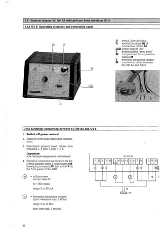
![1 7.6.3 Check of setpoint display
1. Switch on power source, allow at least 15 minutes'
warm-up ti_me.
2. Set switch D (front panel GS8) to "O" position.
3. Adjust zero with the 10-turn potentiometer P (front
panel GS8) to Io% ± < 10 µA.
4. Determine position of switch Y and setpoints I and f as
follows:
4.l X = 0100% *K * F
GK * DN2
0100%= full-scale range (100%)
in volumetric units (V)
per unit time (t)
GK = prirnary constant
(see prirnary head nameplate)
F = 2, if GK value
begins with "L"
= 1, GK value without L
DN = meter size in mm
or inches
=time in seconds (Sec.)
minutes (min), hours (hr)
V =volume
K = constant, see following Table
DN ~ Sec.
mm Liter 25464
m3 25464800
US gal 96396
inches Liter 39.47
m3 39470
US gal 149.4
4.2 Determine position of switch Y
min hr
424.4 7.074
424413 7074
1607 26.78
0.6578 0.0196
657.8 10.96
2.49 0.0415
Use table (front panel GS8) to determine the value Y which
comes closest to the factor X and meets condition Y ~ X.
4.3 Calculate setpoint reading CD current output
y
I = lo% + XCI100%-Io%) [mA]
Io% = current at 0% flowrate, see Fct. 3.1.02
(e.g. 4 mA, at 4 to 20 mA)
I100%= current at 100% flowrate, see Fct. 3.1.03
(e.g. 20 mA, at 014 to 20 mA)
4.4 Calculate setpoint reading (f) freguency output
y
f = x* f100% [HzJ
f10o% = pulses per second at 100% flowrate,
see Fct. 3.2.03
5. SetswitchD (frontpanel GS8) to position „+" or "-" (for-
li!ard or reverse floi'tl).
6. Set switch Y (front panel GS8) to the value determined
by the method described above.
7. Check setpoint readings I or f (see Points 4.3 and 4.4).
8. Deviation < 1.5% of setpoint! If greater, locate fault as
described in Sect. 7.5 + 7.7. First check field power
supply as described in Sect. 7.1.
9. Linearity test: adjust lower Yvalues, readings will drop
in proportion to the determined Yvalue (see Point 4.2).
10. Switch of power source after completing the test.
11. Disconnect GS8.
12. Reconnect leads of prirnary head.
13. Replace housing cover.
14. The system is ready for operation after the power
source has been switched on.
17.6.4 Example
Full scale range 0100% = 280m3/hr
(Fct. 1.01)
Meter size DN = 80 mm c~ 3")
(Fct. 1.05)
Current at Oo% Ioo/o = 4 mA (Fct. 3.1.02)
Current at 0 100% 1100% = 20 mA (Fct. 3.1.03)
Pulses at Owo% f100% = 280 pulses/hr
(Fct. 3.2.03)
Prirnary head GK = 3.571
constant (see nameplate)
Factor (GK valve
without "L") F =l
Constant (V in m3, K = 7074 (see Table)
t in hr / DN in mm)
Calculation „X" and position of switch „Y"
F X 0100% X K 1 X 280 X 7074
X= = =OOM
GK X DN2
3.571 X 80 X 80
Y = 80, position of switch Y, see front panel GS8 (comes
closest to X value and is smaller than X)
Calculation setpoint reading 1 and f
80
4 mA + - - - (20 mA - 4 mA) = 18.8 mA
86.67
Deviations are permissible between 18.5 and
19.l mA (equivalent to ± 1.5%).
y 80
f = X x f100%= - - x 280 pulses/hr =258.S pulses/hr
86.67
Deviations are permissible between 254.6 and
262.3 pulses/hr (equivalent to ± 1.5%).
47](https://image.slidesharecdn.com/dok-150713074349-lva1-app6892/85/Dok-51-320.jpg)
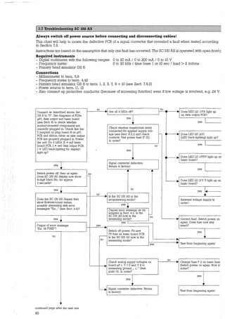
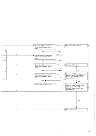
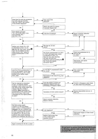
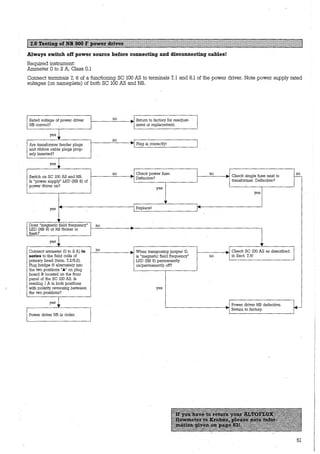
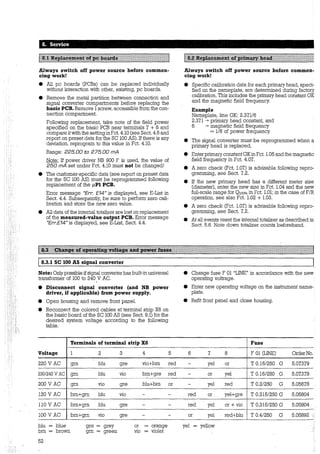
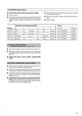
![9. Connection and operating points 011 pc boards, circuit diagrams 'IJld spare parts
LD2/V5
Rx Lx LD1/FSV F2 F3
0
;:!!
"' ~ 8
II
-~ i
iffi
;j
0
··~
'
~
::~4
t r F1[~1~
1XIP<1
1 111
..,.,'""'
; ' 8·r T' .. . . . +
.i..;.
.. ~~
FS•f?
'!'
:t:
• i ~
T
8 8·
~
$-
=I
r ;j
~ 8'
-0
FOl F02 X4a XSa F4 F6 F7 X6
X4a /1 Z 3 4 5 6 7 8 9 10 11 12 13 1415161718 19 202122232425262728 29303132 3334 1 2 3 4 5 6 7 8 9 10 11 12 1314 15 16 1718 19 2021222324 Z5262728 2930313233 34 XSa/
1LL] L]l'""'=ll!'ttll" '1'IUIUlli"~II ~·l ll 1 1toµ P1
PCB
X3/ 1
X21X3 only
withEx-ve1sion
th1mdisconnec-
lingpoints ~
opened "Cl:::
X2/ 1112 3
~
2 3 4
'1!i Q1
"'4 6
5 7
....:_
::>
Rx
'_::J
5 6 Rx
~ 10
1
8 R1
„,
B ,r--1 z R6 J1.. /1
lA1
1t1 47oR
SFH610-2
-14VU
"measured-
va/ue
output
PCB
XI(<_?--
ZO ':'
2;::r>----~
3K9 / discormectfor
L----J---------------------+-++++-t-__,1-H++-"''1~2-"VU""-----~-"[i-1---'-'~---~.DC operatia11 4
220µ ,Y G/1 I F2 ..-3.;.--,„,.-'C::.-,
ye/
R2
3- 3K9
300-------...,c---++---'
4.10-____.,.y
4.Z~-~===~;~~di--i-----------------------------J4.3_ 3~
;-:- 34
- F02 760mAT
71-
12::; FOT 160mAT
10-
~1- · - - - - · - - · - - · - - ·--B ~,
1 FSV-Hybrid 1
1 1
1 1
L. -;--;E;;.-„- -·-rrll '~1•1·_J ~
~;~OKi:gr FSV TZ r ~T1 ~~ Lfci gµ2
39
~P1
54
~ f! 63V T ·T351' JR8 J:;l.,50R
l-'---f-+-1----!<,.,a--,
1
045D5 045D5 ,
1·: )-1/21[1
LJi_:"'SFH610-2
Ll1337T 12R1
Al-Adjust
-1ZVU
0
vvu
25V T - 1 T160mA
c2l_ · v112e ~
fizzoµ ~z
25V 1
""" Ll12930 T-5
„„ 1
·"'f'"---""~R==:="i'/[3 • F3 7
10:1~:: ,,tOV +SV
.L
C!O·T~ J,c6· ~T500mA
0 1p~·~.1p G/3 l+SVJ
2200µ Vl128 8
16V w•.1
F4' 7 1011
•• J;,
rnmmA ~14
F5 ~
+24 VU/+7 SVU*J [7 G/4 ~T200mA
_Q_____
4~t-f ~ R7.324/75VU 63V
V/128 I • 1011 12
F7- 11
T100mA
F6
+35VU/+75VU*I [11 G/5 T200mA
_Q_____ 470pd?
~ 5
R7.4 135/75VU 63VT
•',,,,,,,,,,.,
1
1
1
1
1
1
1
,,,
11
1
1
1
)!
!i'
'---""""'---+--';'-- ,,Vl1ZB """r_I_
GI~+48VU [3
___L
470µ·*· Vl12:::48VU 63V +
T31s;;;;.,,
R7 7
1011
t
s:
!g6
ye/igrn
or X6/
red
8
f--
7
6
~
5
brn
4
gre
vio
3
blu
IL
* only measurab/e with installed measured-value output PCB
all vnltages with primary voltages =rated voltage VUz20% 5Vz0.3V:
'](https://image.slidesharecdn.com/dok-150713074349-lva1-app6892/85/Dok-58-320.jpg)
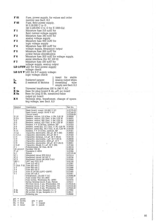
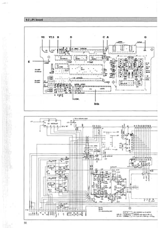
![A Test pointfor the output signal of the input amplifier.
B Test point for the output voltage of the DAC,
0 to - 6.5 Volt
C Test point for the output voltage of the integrator
D Test point for the output voltage of the rectifier
E Test point for the residual pulse generation
bywatchdog
G Measuring ground
V 7.5 Testpoint, supplyvoltage + 7,5 Volt
V 8 Test point, supply voltage - 8 Volt
X 4b Plug board
/[5 11POl1
g: ~ ~ ~ ~ " ~~
2'12' 31 21 21 31 „
~~ ~4-8,IV +7,SV
i I~.;:„
[2
, ~t'---L +12VU
"-u ' .~ 15 1 2
·~/[]
~
-~ u
v.
j VL: +SV
DG212U l.l l.. n
'V- 1~-.!.---------,, • n 1• , 1
~
1
-8,IV _J /[2
-, 2
DG212[J
1..--'- • -
c 1
-
b:J'a-Ts[18
II a.04 71J.tfD'YJiPO
"3'
2 ~ ~
1 133.U
Symbol Description
µPl, board, camp!.
Circuit board
R 1,11 Resistor, meta! film, 1 kOhm, ± 1%, 0,25 W
R 2,20,21 Resistor, meta! film, 22.l kOh_m, ± 1%, 0,25 W
R3 Resistor, meta! film, 4.75 kOhm, ± 1%, 0,5 W
R4 Resistor, meta! film, 562 kOhm,± 1%, 0,5 W
R5 Resistor, 3 x 1 kOhm, network, SIP
R6 Resistor, meta! film, 47.5 kOhm, ± 1%, 0,5 W
R7 Resistor, meta! film, 221 kOhm,± 1%,10,5 W
R8,9 Resistor, meta! film, 150 kOhm, ± 1%, 0,5 W
R 10 Resistor, meta! film, 825 kOhm,± 1%, 0,5 W
R 12,13 Resistor, meta! film, 33.2 kOhm,± 1%, 0,5 W
R 14,15 Resistor, meta! film, 10 kOhm, ± !%, 0,5 W
R 16,17,18,19 Resistor, meta! film, 2.21MOhm,±1%, 0,25 W
R22 1Resistor, 4 * 5 kOhm, network, DIL
c l,2,4,5,6,7,8,11,12,14,17,19,22
1 Capacitor, Sibatit, 0, 1 µF, 63 V
c 3,23,24,27,28,29,30,33,34
c 9,10
1 Capacitor, electrolytic, 1 µF, 50 V
Capacitor, electrolytic, 0.47 µF, 50 V
C 13,15,16,20,21 Capacitor, electrolytic, 10 µF, 35 V
c 18 1 Capacitor, NPO ceramic, 0.047 µF, 50 V
C 25,26,31,33 Capacitor, ceramic, 100 µF, 200 V
D l,2,3,ll,12,13,14 Diode N4148
D 4,6 Diode BAY 86 (1N645)
D5 Diode 1N827
D 7,8,9,10 Zenerdiode, 3 V 3, 0,4 W
IC 1 Integrated circuit DAC 1230 LCD
IC 2,3 Integrated circuit DG 212 CJ
IC4 Integrated circuit SN 74LS590N,O
IC S Integrated circuit TMP 80 C 49 AP-6
IC 6 Integrated circuit MC 14538 BCP
IC 7 Integrated circuit LM 317 T
IC 8 Integrated circuit LM 337 T
IC 9 Integrated circuit NµC 9346 EN
IC 10 Integrated circuit TL 072 ACP.
IC 11 Integrated circuit AMP-01-FX
Al Hybrid
A2 Hybrid
Plug socket, flat, 40 pin, DIL 40 EG
Plug socket, 34 pin, Nr. 67118-017
Pin socket, 26 pin, 90°
Plug socket, flat, 8 pin, DIL 8 EG
Soldering pin
"
'1~
.sv
Va:
ss = [1?
I:<
fA 0,1p
y
'
Hp<J)
-·---1~!!_~··-h- - - , @,' .·® +SV
J_:::: '.;'.,;:ij I<
'·~ ~::. . ' 1
_ -· !.:::LL~_.L..:, 1 tl_k_._ -iJ!!- ~ ~ l li
> ' ~
1~T::ti ~ -.i--A-- 14~ /t t t . $~
--[ ~ ...-~o.avp
I, ;-+-- l"~ ~ij_J -'1. l 1
1: 1 „ 1u J
--1„ 1-- --! " 1--- l11p@
•I 1' rr"· 1
"] ~13VJsfat.
1
1
Al
L --- -ar·~rT .v-:-:_J_- - --- ~ - - - _J ADW-Hybr.
A2
+SV +7,SV-"8,IV KD/1-Hybr.
c8,1V
-
Part No.
2.06034.01
3.07220.02
5.07732
5.07735
5.07733
5.07738
5.07385
5.07736
5.07737
5.07730
5.07731
5.07729
5.07734
5.07278
5.07662
5.07492
5.06924
5.06982
5.07450
5.07567
5.06560
5.05586
5.07674
5.05799
5.05568
5.07305
5.07378
5.07307
3.07218
5.06785
5.06419
5.06739
5.08239
5.07664
5.07663
3.07045.06
3.07172.03
5.06602
5.07374
5.07402
5.07370
5.05898
all vo/tages with primary voltage = rated voltage
SV ±0,3V
7,SV !O,SV
8,IV ±0,6V
vu z20%
57](https://image.slidesharecdn.com/dok-150713074349-lva1-app6892/85/Dok-61-320.jpg)
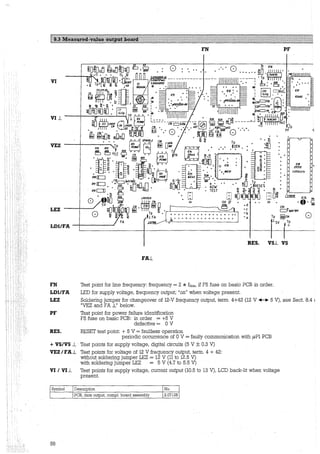
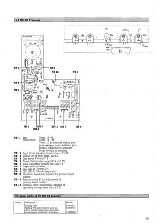
![Part D Technical data, measuring principle, block diagram
Full-scale range
Flowrate 0=100%
Unit
Forward/reverse measurements (F/R)
Current output (term. 5/6)
Current
lo% for 0 = 0%
hoo% for 0=100 %
Low-flow cutoff (SMU)
cutoff "on" value
cutoff "off'' value
Forward/reverse measurements (F/R)
Automatie range change (BA)
Time constant
Max. load at hoo%
Frequency outputs
Pulse rate (at 0=100%)
12-V output
Terminals
Amplitude
Load (totalizer resistance)
24-Voutput
Terminals
Amplitude
Load rating
Pulsewidth
30 or 50 ms
100 ms
200ms
500ms
Pulse duty factor 1:1
160 µs
50µs
Low-flow cutoff (SMU)
cutoff "on" value
cutoff "off" value
Forward/reverse measurements (F/R)
Time constant
lndicatlon outputs
Terminals
Voltage
Current
Load (relay)
Galvanically isolated from .„
Current output 1
Frequency output F
lndication output S
Function
60
operating data programmable
6 liters/hr to 305000 m3/hr or 0.02 to 1342800 US gallons per minute, corresponding to flow velocity
v = 0.3 to 12 m/s or 1to 40 ft/s
m3, liters or US gallons per second, minute or hour, and 1 field-programmable unit,
e.g. liters per hour 9r US million gallons per day
0100% separately adjustable for both directions
galvanically isolated, operating data programmable
~i~ 18~~ }~djustable in increments of 1 mA
1to19%}
2
to
20
% of 0100%, adjustable in1% increments, independent of frequency output
selectable performance, direction identified via status indication or frequency output
programmable in 1% increments from 1:20 to 1:1.25 (equivalent to 5 to 80% of 0100%)
0.2 to 3600 seconds, programmable in increments of 1or 0.1 seconds
1
20
[V A] in kohms te.g. 1 kohm at 20 mA, 4 kohms at 5 mA)
100% m
'galvanically isolated, operating data programmable
10 to 36000000 pulses per hour
0.167 to 600000 pulses per minute
0.0028to10000 pulses per second (=Hz)
optionally in pulses per m3, liters or US gallons
for electronic totalizers (EC)
4+42
12 V, changeable to 5 V
min.1 kohm
for electromechanical (EMC) or electronic (EC) totalizers
4 +41
24V
see "pulse width" table below
Frequency f = F100%
0.0028 Hz <f s 10 Hz
0.0028 Hz <f s 5 Hz
0.0028 Hz <f s 2.5 Hz
0.0028 Hz <f s 1 Hz
10 Hz <f S 1000 Hz
1000 Hz <f s 2547 Hz
2547 Hz <f s 10000 Hz
Max. load current (24 V)
S200mA
5200mA
S 200 mA
5200mA
S 50mA
S 50mA
S 50mA
Min. load (24 V)
2 120 Ohm
2 120 Ohm
2 120 Ohm
21200hm
2 5000hm
2 5000hm
2 500 Ohm
1 to 19% } of 0 10o%, adjustable in 1% increment~, independent of current output
2 to 20%
selectable performance, direction identified via status or current output
0.2 second or same as current output (see above)
Current output Frequency output
1 F
5+6 4+4.1
U s 35 VoltDC U=24 Volt DC
l1oad S 22 mA l1oad S 200 mA
programmable
Rcoil = U/lmax Rcoil 2150 ohms
yes
yes
yes no
only indication of only indication of
flow direction for F flow direction for 1
(F/R operation) (F/R operation)
or operation indicator
lndication output
s
4+4.3
U=24 Volt DC
l1oad S 30 mA
Rcoil 2 1 kohms
yes
no
indication of flow directior
for 1 and/or F,
trip point for 1or F,
seif diagnostics
(error indication),
low-flow cutoff SMU
counter overflow,
operation indicator
or automatic range
change BA](https://image.slidesharecdn.com/dok-150713074349-lva1-app6892/85/Dok-64-320.jpg)
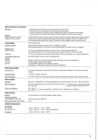
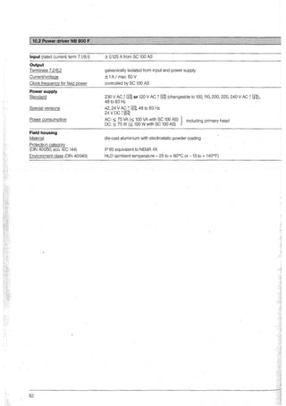
![Frequency output
F Error (±) as % of flowrate (measured value)
v Flow velocity in m/s (ft/s)
1.4
Reference conditions
. Product
Power supply (line voltage)
Ambient temperature
Warm-up time
Maximum error of calibration system
lnlet/outlet runs
Primary head
Primary Meter size
head
ON
mm
IFS 5000 2.5- 6
IFS 5000 10 - 100
IFS 2000 150 - 250
IFS 4000, M900 10 - 25
' 32 - 800
900 -1200
1250 -2000
>2000
1l at extra charge
2l SC 100 AS/ NB
Currenf output
External influences
Ambient temperature
Frequency output
Current output
Power supply
Load.·
inches
1/10 - 1/4
3/s - 4
6-10
3/s - 1
11/4-32
36-48
50-80
>so
±F
[%]
f1.0
0.8
0.6
-------····················---------®
0.4 -------··················---------©
-------·····················---------®
0.2 -------················---------@
0
0 0.5 1
0 1.5 3
2
6
10
30
11
33
~v[m/s]
36 V [ft/s]
Water at 10 to 30°C (50 to 86°F) and >300 µSlcm (µmho/cm)
UN (±2%)
20 to 22°C (68 to 71.6°F)
60 min.
10 * times smaller than F
5 DN/2 DN (Curves A + B: 10 DN/5 DN), DN = meter size
properly grounded and centered
Standard details Option 1)
v ~ 1 m/s v ~ 1 m/s
or 3 ft/s
v <1 m/s or <3 ft/s
or 3 ft/s
Curve
%v.MV
o/ov. MV+ mm/sor
%v.MV
% of MV + inch/s
±0.5%
± (0.4 % + 1 mm/s) or
D -
± (0.4 % + 0.04 inches)
±0,4%
± (0,3 % + 1 mm/s) or
c ±0,2%
± (0.3 % + 0.04 inch/s)
±0.4%
± (0.3 % + 1 mm/s) or
c -
± (0.3 % + 0.04 inch/s)
±0.4%
± (0.3 % + 1 mm/s) or
c ±0,2%
± (0.3 % + 0.04 inch/s)
±0.4%
± (0.3 % + 1 mm/s) or
c ±0.2%2)
± (0.3 % + 0.04 inch/s)
±0.4%
± (0.3 % + 1 mm/s) or
c ±0.3%
± (0.3 % + 0.04 inch/s)
±0,5%
± (0,4 % + 1 mm/s) or
D -
± (0.4 % + 0.04 inch/s)
same as above accuracies for frequency output plus ...
genrally: ± 0.05 % * 20 mA
hoo% - lo%
0 to 20 mA: ± 0.05 %
4 to 20 mA: ± 0.062 %
of full-scale range
v < 1 m/s or <3 ft/s
%v.MV + mm/sor
% of MV + inch/s
- -
± (0,1 % + 1 mm/s) or
± (0.1 % + 0.04 inch/s)
-
± (0.1 % + 1 mm/s) or
± (0.1 % + 0.04 inch/s)
± (0.1 % + 1 mm/s)2lor
± (0.1 % + 0.04 inch/s)2l
± (0.2 % + 1 mm/s) or
± (0.2 % + 0.04 inch/s)
-
Curve
-
A
-
A
A
B
-
± 0.01 % } of measured value per
± 0.025 % 1Ktemperature variation
or
± 0.006 % } of measured value per
± 0.014 % 1°F temperature variation
± 0.05 % of measured value at 10% variation
± 0.02 % of measured value at max. load (see under "current output")
63](https://image.slidesharecdn.com/dok-150713074349-lva1-app6892/85/Dok-67-320.jpg)
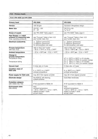
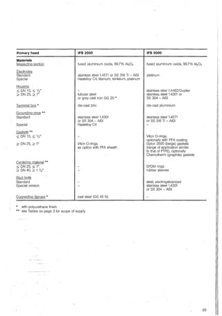
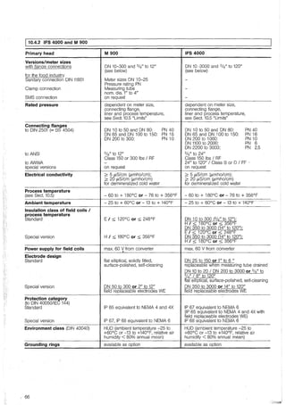
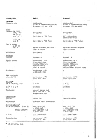
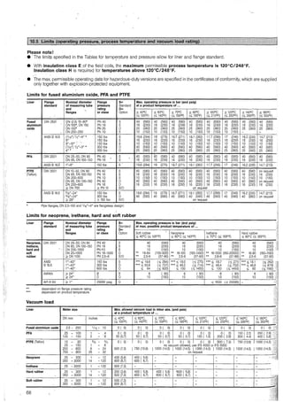
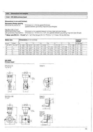
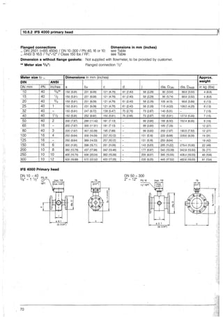
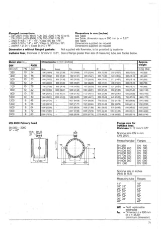
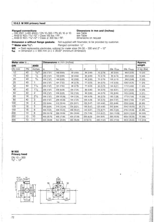
![M 900 with sanitary connection to D!N 11851
Dimensions in mm and (inches)
Meter size Dimensions in mm (inches)
ON mm a b*
10 and 20 200 (7.87) 223 (8.78)
25 and 32 200 !].87) 245 (9.65)
40 and 50 200 (7.87) 290 (11.42)
65 and 80 200 (7.87) 310 (12.20)
100 and 125 250 (9.84) 370 (14.57)
M 900 primary head
with sanitary connection to DIN 11851
ON 10 - 125 I PN 10
a±0.5%
M 900 with clamp connection
Dimensions in mm and (inches)
75
c
Meter size Dimension in mm (inches)
inches a
1 200 IJ.87)
11h 200 (7.87)
2 200 IJ.87)
3 200 (7.87)
4 250 (9.84)
M 900 primary head
with clamp connection
1" - 4"
0
"'ci
±.
"'+
"-
.0
PG 16
a±0.5%
b* c**
245 ( 9.65) 96 (3.78)
245 ( 9.65) 96 (3.78)
290 (11.42) 184 (7.24)
310 (12.20) 184 IJ.24)
370 (14.57) 234 (9.21)
75
c
d -
77 (3.03)
77 (3.03)
99 (3.90)
109 (4.29)
139 (5.47)
** For stainless steel housing: Dimension c + 14 mm or + 0.55"
c** d j
92 (3.62) 66 (2.60) 70 (2.76)
96 (3.78) 77 (3.03) 94 (3.70)
184 IJ.24) 99 (3.90) 94 (3.70)
184 !J.24) 109 (4.29) 94 (3.70)
234 (9.21) 139 (5.47) 125 (4.92)
** For stainless steel housing: Dimension c + 14 mm or + 0.55"
dia. e dia. f j dia. k dia. 1 m
18.5 (0.71) 49.6 (1.95) 94 (3.70) 25.5 (1.00) 22.1 (0.87) 25.4 (1.00)
28.5 (1.12) 49.6 (1.95) 94 (3.70) 38.2 (1.50) 34.8 (1.37) 25.4 (1.00)
44.5 (1.73) 76.6 (3.02) 94 (3.70) 51.0 (2.01) 47.5 (1.87) 25.0 (0.98)
64.5 (2.52) 117.7 (4.63) 94 (3.70) 76.3 (3.00) 72.9 (2.87) 25.4 (1.00)
93.8 (3.66) 117.7 (4.63) 125 (4.92) 108.9 (4.25) 97.6 (3.84) 24.3 (0.96)
m a ±0.5%
73](https://image.slidesharecdn.com/dok-150713074349-lva1-app6892/85/Dok-77-320.jpg)
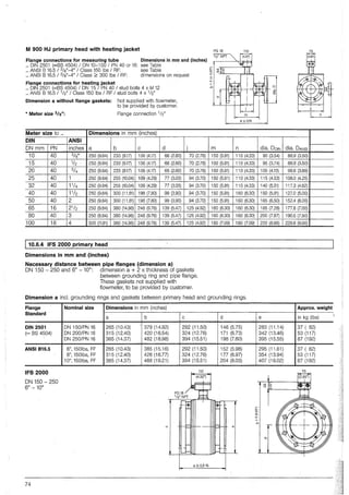
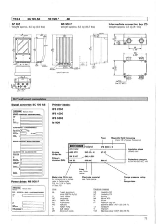
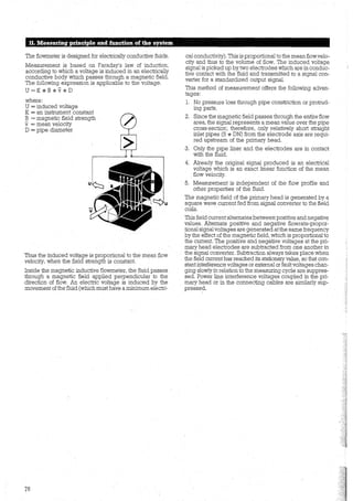
![13. Signal converter SC 100 AS/HPC/S
Use of the „µPl-HPC" pc board and special software
„8.06267.xx" in an SC 100 AS requires a different layout of
menu 4.00. Other menu items are not affected.
4.02 ENTRYCODE
4.03 OUTP. HOLD
4.04 UN/TTEXT
4.05 FACT. QUANT.
4.06 FACT. TIME
4.07 F/ELD FREQ.
4.08 SCALE SEL.
4.09 FIELD GUR.
4.10 NO/SE
4.11 LIMITCNT
4.12 LIMIT VAL
78
Language of display texts, Sect. 5.11
e GB/USA (= English)
• D (= German) • F (= French)
• SF (= Finnish) • others endin
Coding for entry into
programming mode? Sect. 5.12
• NO = entry with l]I key
• YES = entry with keys
ccccmm
Hold values of outputs
during programming?
NO or YES (Sect. 5.13)
Text for field-programmable
unit, Sect. 5.14
A„.Z / a...z / 0„.9 / _ (= s ace)
Conversion factor for
quantity FM, Sect. 5.14
Factör FM= quantity l§er 1 m3
Range: 0.00001*10- to
9.99999*1o+9
Converi;;ion factor for time FT
Sect. 5.14
Factor FT in seconds
Range: 0.00001*10-9
to
9.99999* 10+9
Magnetic field frequency,
Sect. 5.15+8.2
• 1/6 • 1/16 • 1/32
Select preamplification, Sect. 13
• AUTO (automatic)
e HIGH FLOW (high flow range)
• MED. FLOW (medium flow range)
• LOW FLOW (low flow range)
Input of field current
Range: 225.00 to 275.00 mA
(see sticker at term 7 + 8 on
"basic" pc board/with power driver
NB 900 F always ± 250 mA)
Not tobe changed, see Sect. 7.2 + 8.1
Noise rejection, see Sect. 13
e NO e YES
Counter for off-limit condition
(appears only if YES entered under
(Fct. 4.10 NO/SE), see Sect. 13
Range: 001 to 250
Limit value for noise amplitude
(appears only if YES entered under
Fct. 4.10 NO/SE), see Sect. 13
Range: 01 to 90 PERCENT
Fct. 4.07 Magnetic field frequency
In addition to the normalmagnetic field frequencies, three
new values are available. These are „1/2", „SPEC.
1/12"and „SPEC. 1/1B"ofthe power frequency. The fol-
lowing chart shows the transientrecove:ry time for the mag-
netic field and the integration time ofthe measuring signal.
Rpower-line fr'fllency
nnn nnnnnnnnnnnnnn
LJLJUULJUUUUUUUULJULJLJUL
= measuring signal integration time
Fct. 4.08 Range selection
This function can be used to influence the preamplifier
stage. In the AUTOmode, the microprocessor automati-
cally takes over the setting in keeping with the interfe-
rence level and the size of the wanted signal. In some
applications it may prove useful to change the gain
manually. Since there are no hard and fast rules for apply-
ing Fct. 4.08, itis advisable to determine the best setting by
trial and error.
Fct. 4.10 Noise rejection
This function activates a special noise rejection filter
(input: YES). The task of this filter is to reject spurious
peaks and thus provide steadier display and output of the
measured values. The data of the two following func-
tions, Fct. 4.11 and Fct. 4.12, are used for operation of
the noise rejection filter. These input functions are not
shown in the menu when NOhas been entered in Fct. 4.10.
The block diagram below serves to illustrate filter action
and the parameters of functions 4.11 and 4.12.
time constant
Fct. 3.1.05
to data
processing](https://image.slidesharecdn.com/dok-150713074349-lva1-app6892/85/Dok-82-320.jpg)
![Functional description
The old measured value, weighted with the time constant,
is subtracted from the nei'1ly calculated measured value1
and the result checked to establish whether it exceeds the
limit set inFunction 4.11. Ifitdoes, the totalizer countincrea-
ses and the differential signal is limited to the specified
limit value..To this differential signal is added the old mea-
sured value again, and forwarded to the time constant pro-
gram. When the totalizer attains the default value from
function 4.11, the limiter unit is bypassed. If the set limit is
not exceeded, the totalizer is reset to the value 'O', and the
limiter bypass de-energized. Two examples are given
below to illustrate the function.
Example 1:
Transient interference superposed on the measured
value.
Ua 100%
rise and fall determined
by Fct. 4.12
In this example it is important that the nurnber of violations
of the limit value from Function 4.11 be selected such that
the limiterfunction always remains activated. The following
equation can be used to establish by approximation the
input values for function 4.11:
LIMIT CNT = max. duration of interference (in sec)
0.06
For function 4.12, the maximum user-acceptable deviation
from the measuring signal is the determining factor. But
noise duration, noise amplitude and the shape ofthe curve
are also crucial factors. This parameter can only be deter-
minedby trial and error, since too many factors would have
to be considered before any hard and fast rule can be laid
down.
Retrofitting the µPl-HPC board
1. Note down all input pa.tameters.
2. De-energize the device!
3. Exchange the µPl board and the EPROM for the µP2.
(if necessary unsolder OTP. and insert a 28-pin socket-.
mount).
4. Switch on device.
5. The device displays Errl4 and EOl.
(Also refer to page 25 of SC 100 AS operating instruc-
tions, current calibration data different!)
6. Press key E 4 times, the values are corrected automati-
cally.
7: Enter all input parameters again according to the old
setting. With the new extra functions it is advisable to
select a.l:)asic setting first,
.(i. e. 4.7 = 1/6 (f line); 4.8 = auto; 4.10 = no).
8. Calibrate the zero.
: The device is_ again fully functionable. The new facilities
' can ,now be used according to application. Repeat zero
calibration at the end of the experimental phase.
Example 2:
The measured value skips from 0% to 100% ofthe flowrate.
:t--Jo interference and no noise signals.
Ua 100%
t=O lu
Number of limit violations set under
Function 4.11 reached. Measured value
transmitted unfiltered.
)
As shown in the diagram, the step change of the wanted
signal is forwarded to the outputs after a time interval. The
rate of rise is dependent on the setting of time constant T
and the value from Fct. 4.12 LIMIT VAL. The time constant
in the t < tu range is:
TL
. . T[s]
rrrut = X 100%
LimitVal
given a 100% skip of the wanted signal.
The instant tu of switchover to the set time constant T is:
tu =LimitCnt X 0.06 s
For delta L1 Ue (%) LimitVal we obtain a maximum output
response of:
L1Ua LimitVal
-- = ---
L1T T
where T is the TIMECONSTANT set under Fct. 3.1.05.
Note: Additional dead times for all signal outputs result
from functions 4.11and4.12. This means that function 3.1.05
T-CONST.I is no longer the sole determining factor for the
response time of the SC 100 AS.
79](https://image.slidesharecdn.com/dok-150713074349-lva1-app6892/85/Dok-83-320.jpg)
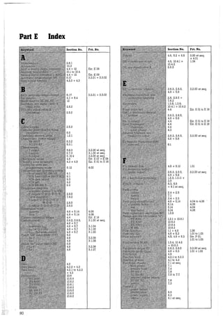
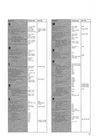
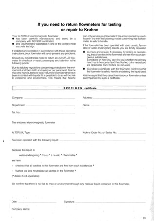
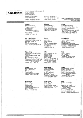


![[Envimart's Products] Đồng hồ điện từ đo lưu lượng nước, MagFlux hãng MJK](https://cdn.slidesharecdn.com/ss_thumbnails/en-305-magflux-datasheet-1711-190216143317-thumbnail.jpg?width=640&height=640&fit=bounds)


