Download to read offline

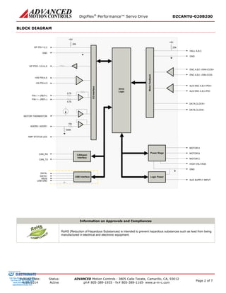
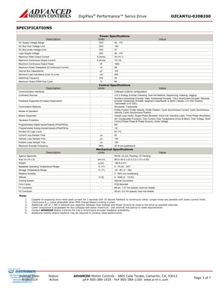
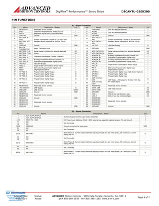

The DigiFlex® PerformanceTM Servo Drive DZCANTU-020B200 is a digital servo drive designed to drive brushed and brushless servomotors from a compact form factor. It operates in torque, velocity, or position mode using Space Vector Modulation for higher efficiency. The drive features CANopen and USB interfaces, programmable I/O, and supports various feedback devices and motor types. It provides peak currents of 20A and continuous currents of 10A from a 40-175VDC supply voltage.


