SlideShare a Scribd company logo
1 of 32
DKM CO.,LTD. 143
SPEEDCONTROL
SPEED CONTROL SYSTEM
INDEX
SPEED CONTROL MOTOR FEATURES 144
6W ( 70mm) 153
10W ( 70mm) 155
15W ( 80mm) 157
25W ( 80mm) 159
40W ( 90mm) 161
60W ( 90mm) 163
90W ( 90mm) 165
120W ( 90mm) 168
180W ( 90mm) 171
144 DKM CO.,LTD.
DKM Motor allow you to easily set and adjust the speed. DKM Motor offers three kinds of AC speed control
as shown below. Select the best system depending upon your application.
DIGITAL TYPE (CONNECTOR Type / Digital Display) FX1000A Series
UNIT TYPE (CONNECTOR Type) DSA Series
SOCKET TYPE DSK Series
Features of Speed Control Motor
DSK Controller DSKS Controller
DKM CO.,LTD. 145
Speed-Torque Characteristics of Speed Control Systems
The speed-torque characteristics line of all AC speed control motors characteristics is shown in the figure below.
Each set speed changes slightly according to the change in load torque.
Safe Operation Line and Permissible Torque When Using a Gearhead
Input power to the speed control motor depends on the load and speed. The greater the load, and the lower the speed, the
greater an increase in motor temperature.In the speed-torque characteristics graph, the line is referred to as the safe
operation line, while the area below the line is called the continuous operation area.
The safe operation line, measured according to motor temperature, indicates its operational limit for continuous usage with
the temperature. Whether the motor can be operated at a specific torque and speed is determined by measuring the
temperature of the motor case. In general, if the motor's case temperature is below 90 (194 ), continuous operation is
possible, considering the insulation class of motor coil winding. But the motor life could be extended with lower motor
temperature. So it is recommended that the motor be used under conditions that keep the motor temperature low.
DKM has two kinds of cooling fan ; General fna (F type) and Powerful fan (F2 type). F fan is attached in motor shaft and its
speed depends on the motor shaft speed. So in slow speed of motor, there is very weak cooling effect. In the application
where motor speed should be changed from low speed (below 1,000 rpm) to hight speed like speed control motor, F2 fan is
needed so that cooling effect keep constantly regardless of the motor speed.
In case of speed control motor and inverter motor, DKM is employing F2 type fan into them basically. ; In special application
or by user s request F type fan can be employed in speed control motor and inverter motor.
And please be advised that in all motors, F2 fan can be attached by user s request.
SPEEDCONTROL
Technical Reference
Speed Control Methods of Speed Control Systems
By a potentiometer, the speed setting voltage is supplied.
The motors speed is sensed and the speed signal voltage is supplied.
The difference between the speed setting voltage and speed signal voltage is supplied.
A voltage determined by the output from the capacitor is supplied to the motor so that it will reach the set speed.
145-1 DKM CO.,LTD.
The FX1000A series combines a control unit and AC speed Control
motor. Connection between the motor and control Unit is simplified
by an easy-to-use connector.
Digital Type Speed Control Motor
FX1000A control system
Features
Easy Connection
Control units combine the control pack, potentiometer and capacitor into one device. Operation is possible just by connecting
the control unit into power supply after connecting the motor and control unit together using the connector.
Easy Operation
The speed can be set easily with the potentiometer on the front panel of the control unit.
DIGIRAL DISPLAY
The motor speed can see directly on the front panel of display of the control unit.
System Configuration
Extension Cables
(Accessories)
( Page 236 )
Clutch & Brake
Motor Mounting Plate (Accessories)
( Page 234)
FX1000A Controller
Capacitor
AC
Power
Supply
Worm solid type Worm hollow type
DKM CO.,LTD. 145-2
SPEEDCONTROL
Item Detail
Rated Input Voltage 220 VAC 50/60 Hz
Workable Voltage from -15% to +10% of 220VAC
Consumption Power Less than 4VA
Control Mode Phase Loop Control (0 to 220 VAC)
Input Frequency 10Hz ~ 360Hz (TACHO)
Power On-Off Signal Red color of LED
Speed Set Range 100 ~ 1750(RPM)
Ambient Temperature from -10 to +55
Ambient Humidity 35 ~ 85% RH
Weight 300g
Dimension 60(w) x 100(h) x 92(d) mm
Insulation Resistance 100 or more when 500V mega is applied between the windings and the housing after rated motor
operation under normal ambient temperature and humidity
Dielectric Strenght Sufficient to withstand 1.5KV at 50/60Hz applied between the windings and the case after rated motor
operation under normal ambient temperature and humidity for 1min.
Measurement CAT III
FX1000A Controller Specification
General Specification
Motor capacity / Rated Current
Specification Output Capacitor Rated Current
7SDGC - 6G 6W 0.7uF 0.15A
7SDGC - 10G 10W 1.0uF 0.18A
8SDGC - 15G 15W 1.5uF 0.26A
8SDGC - 25G 25W 2.0uF 0.32A
9SDGC - 40G 40W 2.5uF 0.47A
9SDGC - 60F2P 60W 4.0uF 0.63A
9SDGC - 90F2P 90W 5.0uF 1.05A
9SDGC - 120F2P 120W 6.0uF 1.2A
9SDGC - 180F2P 180W 6.5uF 1.6A
145-3 DKM CO.,LTD.
Dimension
Circuit Diagram
DKM CO.,LTD. 145-4
Terminal Type
No Fan Powerful Fan
(CAPACITOR)
(CAPACITOR)
Connector Type
Operation Method : At first connect each terminal on the rear panel of the controller with the motor as instructed in connection diagram. And then
input the external power to both of the terminal AC for the rated speed operation. Now you can adjust the main volume on the center of front panel
to control the output speed of motor as user want.
* Direction : CW : (CW+COM)
CCW : (CCW+COM)
* Capacitor : Connect (9-6) or (9-3) According to it s capacity
* CW : (COM+CW)
* CCW : (COM+CCW)
200 - 240 V a.c
50 - 60 Hz 4VA
!
0.7uF -
2.5uF
(CAPACITOR)
4.0uF -
8.0uF
(CAPACITOR)
DKM CO.,LTD. 147
The DSK control system combines a control unit and AC
speed control motor. Connection between the motor and
control unit is simplified by socket.
Socket Type Speed Control Motor
DSK control system
Features
Compact Speed Control Pack
It is compact speed control pack with small pulg-in (8 pin) type.
Easy Operation
The speed can be set easily with the potentiometer on the front panel of DSK model. In case of DSKS model, the
potentiometer (speed control volume) could be separated from body.
System Configuration
1. DSK controller
The variable resistor for speed control is installed in front of body like below
Motor
Gearhead
Capacitor
Socket
AC
Power
Supply
DSK Controller
2. DSKS controller
The remote speed control is available by separate variable resistor like below.
Motor
Gearhead
Capacitor
Potentiometer
AC
Power
Supply
DSKS Controller
SPEEDCONTROL
(DSK Controller) (DSKS Controller)
148 DKM CO.,LTD.
DSK(S) Controller Specification
General Specification
Dimension
(1) DSK
(2) DSKS
Item Detail
Rated Input Voltage 220 VAC 50/60 Hz
Workable Voltage from -15% to +10% of 220VAC
Consumption Power Less than 4VA
Control Mode Phase Loop Control (0 to 210 VAC)
Power On-Off Signal Red color of LED
Allowed RPM Range 90 ~ 1750 RPM
Ambient Temperature from -10 to +55
Weight 160g
DSK (variable resistor installed) : 58(W) x 85(H) x 91(D)mm
DSKS(variable resistor separated) : 49.5(W) x 77(H) x 100(D)mm
100 or more when 500V mega is applied between the windings and the housing after rated motor
operation under normal ambient temperature and humidity
Sufficient to withstand 1.5KV at 50/60Hz applied between the windings and the case after rated motor
operation under normal ambient temperature and humidity for 1min
Insulation Resistance
Dimension
Dielectric Strength
DKM CO.,LTD. 149
Connection Diagrams
For CCW operation, please change Red and blue.
How to Read Specifications
Lead Wire Type
7SDG(S)A-6G
7SDG(S)B-6G
7SDG(S)C-6G
7SDG(S)D-6G
7SDG(S)E-6G
7SDG(S)F-6G
-
-
-
-
-
-
1/125
Single Phase 110
Single Phase 115
Single Phase 220
Single Phase 220
Single Phase 230
Single Phase 230
60
60
50
60
50
60
90~1700 360 36 5.04 200 20 2.80 400 40 5.60 0.25 70
432 43 6.05 240 24 3.36 480 48 6.72
360 36 5.04 200 20 2.80 400 40 5.60
432 43 6.05 240 24 3.36 480 48 6.72
360 36 5.04 200 20 2.80 400 40 5.60
0.70 73
90~1400
90~1700
90~1400
90~1700
Output
HP W VAC Hz Wrpm gfcm mN.m oz-in
Voltage
Permissible Torque
1200rpm 90rpm
Starting
Torque
Power
Consumption
Freq.
A
Curren
t
Speed
Range
6
Terminal Box Type
Model
7SDG -6G : Pinion Shaft Type
7SDS -6 : Round Shaft Type
gfcm mN.m oz-in gfcm mN.m oz-in
Maximum Output : This refers to the amount of work that can be performed in a given period of time with the combination of motor and control
pack. It also expresses the maximum output that can be produced within the usage limit line on the speed-torque characteristics graph.
Speed range : This refers to the range of variable speed with the combination of motor and control pack. For speed control motors, the
variable speed range varies with the size of load torque.
Permissible torque : This refers to the maximum torque that can be produced below the safe-operation line or the permissible torque with
gearhead attached at the most commonly used speeds (1200 rpm, 90 rpm).
Starting torque : This refers to the size of torque that can be produced instantaneously at motor start-up with the combination of motor and
control pack.
Current : This refers to the current sent into the control pack at the maximum output.
SPEEDCONTROL
DSK DSKS
150 DKM CO.,LTD.
Output
W
Frame size
mm (in.)
Type
Power (Voltage)
Single phase
100/110/115V 200/220/230V 200/220/230V 380 V 440V
Three phase Page
Speed Control Motor Line-Up
Lead Wire - - -
Terminal box - - - - -
Lead Wire - - -
Terminal box - - - - -
Lead Wire - - -
Terminal box - - -
Lead Wire - - -
Terminal box - - -
Lead Wire - - -
Terminal box - - -
Lead Wire - - -
Terminal box - - -
Lead Wire - - -
Terminal box - - -
Lead Wire - - -
Terminal box - - -
Lead Wire - - - -
Terminal box - - - -
6
10
70(2.76)
15
25
40
60
90
120
180
80(3.15)
90(3.54)
How to Read Speed-Torque Characteristics
Safe-operation line
The safe-operation line, measured by the motor s temperature,
indicates its operational limit for continuous usage with the
temperature level below the permissible maximum (In case of using
a reversible motor, it is measured by 30 minutes operation.)
Whether the motor can be operated continuously or not, is judged
by measuring the temperature of the motor case. When the
temperature of the case is below 90 (194 ), the motor is capable
of continuous operation.
Permissible torque when gearhead is attached :
When using a gearhead, be aware that it is necessary to operate
below the maximum permissible torque. If the actual torque
required should exceed the maximum permissible torque, it may
cause possible damage to the motor and/or may shorten its life
span.
General Specifications
Item Specifications
Insulation Resistance 100 or more when 500 VDC is applied between the windings and the frame after rated motor opeation under normal
ambient temperature and humidity.
Dielectric Strength Sufficient to withstand 1.5 KV at 50 Hz and 60 Hz applied between the windings and the frame for 1 minute after rated
motor operation under normal ambient temperature and humidity.
Temperature Rise Temperature rise of windings are 80 (144 ) or less measured by the resistance change method after rated motor
operation with connecting a gearhead or equivalent heat radiation plate. [ Three-Phase 6W type : 70 (126 ) ]
Insulation Class Class B [ 130 (266 ) ]
Overheat Protection In single-phase 50Hz, the thermal protector is built in. (Automatic return type) In case of others, it can be built by order.
Operating temperature, open : 130 5 (266 9 ) close : 82 15 (179.6 27 )
Ambient Temperture Range -10 ~ + 40 (14 ~ 104 ) (nonfreezing)
Ambient Humidity 85% maximum (noncondensing)
153
155
157
159
161
163
165
168
171
DKM CO.,LTD. 151
70mm(2.76in.)
SPEED CONTROL MOTOR
6W
Motor Specification
Enter the gear ratio in the box ( ) within the model name. A colored background indicates gear shaft rotation in the same direction as the
motor shaft ; a white background indicates rotation in the opposite direction.
The speed is calculated by dividing the motor's synchronous speed (50Hz : 1500 r/min, 60 Hz : 1800 r/min) by the gear ratio.
The actual speed is 2~20% less than the displayed value, depending on the size of the load.
Permissible Torque When using gearhead
SPEEDCONTROL6W
LEAD WIRE TYPE DSKDSA
Speed-Torque Characteristics
Enter the Phase & Voltage code in the box( ) within the motor model name.
Pinion Shaft is for attaching gearhead and Round Shaft is for using motor only.
: Contains a built-in thermal protector. If a motor overheats for any reason the thermal protector opened and the motor stops. When the
motor temperature Drops, the thermal protector closes and the motor restarts. Be sure to turn the motor off before inspecting. By
attaching F2 FAN additionally, temperature reducing of over 10 could be available.
TP
Lead Wire Type
7SDG(S)A-6G
7SDG(S)B-6G
7SDG(S)C-6G
7SDG(S)D-6G
7SDG(S)E-6G
7SDG(S)F-6G
-
-
-
-
-
-
1/125
Single Phase 110
Single Phase 115
Single Phase 220
Single Phase 220
Single Phase 230
Single Phase 230
60
60
50
60
50
60
90~1700 500 50 7.0 300 30 4.2 400 40 5.6 0.25 2.5 250
500 50 7.0 300 30 4.2 400 40 5.6 0.15 0.7 400
90~1400
90~1700
90~1400
90~1700
Output
HP W VAVAC Hz rpm gfcm mN.m oz-in
Voltage
Permissible Torque
1200rpm 90rpm
Starting
Torque
Condense
rFreq. Current
Speed
Range
6
Terminal Box Type
Model
7SDG -6G : Pinion Shaft Type
7SDS -6 : Round Shaft Type
gfcm mN.m oz-in gfcm mN.m oz-in
TP
TP
TP
TP
TP
TP
3 3.6 5 6 7.5 9 12.5 15 18 25 30 36 40 50 60 75 90 100 120
1.2 1.5 2.0 2.4 3.0 3.6 5.1 6.1 7.3 9 11 13 15 17 20 25 30 30 30
0.12 0.15 0.20 0.24 0.30 0.36 0.51 0.61 0.73 0.91 1.1 1.3 1.5 1.7 2.0 2.5 3 3 3
1.06 1.32 1.77 2.1 2.6 3.2 4.5 5.4 6.4 8.0 9.7 11.5 13.2 15 18 22 26 26 26
1.2 1.5 2.0 2.4 3.0 3.6 5.1 6.1 7.3 9 11 13 15 17 20 25 30 30 30
0.12 0.15 0.20 0.24 0.30 0.36 0.51 0.61 0.73 0.91 1.1 1.3 1.5 1.7 2.0 2.5 3 3 3
1.06 1.32 1.77 2.1 2.6 3.2 4.5 5.4 6.4 8.0 9.7 11.5 13.2 15 18 22 26 26 26
0.7 0.8 1.2 1.4 1.8 2.1 3 3.5 4.2 5.5 6.4 7.6 8.5 10 11 15 17 20 23
0.07 0.08 0.12 0.14 0.18 0.21 0.30 0.35 0.42 0.55 0.64 0.76 0.85 0.99 1.1 1.5 1.7 2.0 2.3
0.62 0.71 1.1 1.2 1.6 1.9 2.6 3.1 3.7 4.9 5.7 6.7 7.5 9 10 13 15 18 20
0.7 0.8 1.2 1.4 1.8 2.1 3 3.5 4.2 5.5 6.4 7.6 8.5 10 11 15 17 20 23
0.07 0.08 0.12 0.14 0.18 0.21 0.30 0.35 0.42 0.55 0.64 0.76 0.85 0.99 1.1 1.5 1.7 2.0 2.3
0.62 0.71 1.1 1.2 1.6 1.9 2.6 3.1 3.7 4.9 5.7 6.7 7.5 9 10 13 15 18 20
rpm
1200
90
Voltage Gear Ratio
110/115
220/230
110/115
220/230
Motor/Gearhead
kgf cm
N.m
lb-in
kgf cm
N.m
lb-in
kgf cm
N.m
lb-in
kgf cm
N.m
lb-in
7SDG -6G /
7GBD BMH
150 180
30 30
3 3
26 26
30 30
3 3
26 26
30 30
3 3
26 26
30 30
3 3
26 26
152 DKM CO.,LTD.
* Note Above table indicates output shaft
dimension made by user s request
and indicates the basic
dimension in factory shipping.
Dimension
Connection Diagrams Please refer to page 148, 151.
DKM CO.,LTD. 153
70mm(2.76in.)
SPEED CONTROL MOTOR
10W
Motor Specification
Enter the gear ratio in the box ( ) within the model name. A colored background indicates gear shaft rotation in the same direction as the
motor shaft ; a white background indicates rotation in the opposite direction.
The speed is calculated by dividing the motor's synchronous speed (50Hz : 1500 r/min, 60 Hz : 1800 r/min) by the gear ratio.
The actual speed is 2~20% less than the displayed value, depending on the size of the load.
Permissible Torque When using gearhead
LEAD WIRE TYPE DSKDSA
SPEEDCONTROL10W
Enter the Phase & Voltage code in the box( ) within the motor model name.
Pinion Shaft is for attaching gearhead and Round Shaft is for using motor only.
: Contains a built-in thermal protector. If a motor overheats for any reason the thermal
protector opened and the motor stops. When the motor temperature Drops, the thermal
protector closes and the motor restarts. Be sure to turn the motor off before inspecting. By
attaching F2 FAN additionally, temperature reducing of over 10 could be available.
TP
Lead Wire Type
7SDG(S)A-10G
7SDG(S)B-10G
7SDG(S)C-10G
7SDG(S)D-10G
7SDG(S)E-10G
7SDG(S)F-10G
-
-
-
-
-
-
1/75
Single Phase 110
Single Phase 115
Single Phase 220
Single Phase 220
Single Phase 230
Single Phase 230
60
60
50
60
50
60
90~1700 800 80 11.2 380 38 5.3 500 50 7.0 0.30 3.0 250
800 80 11.2 380 38 5.3 500 50 7.0 1.00 1.0 400
90~1400
90~1700
90~1400
90~1700
Output
HP W gfcm mN.m oz-in
Permissible Torque
1200rpm 90rpm
Starting
Torque
10
Terminal Box Type
Model
7SDG -10G : Pinion Shaft Type
7SDS -10 : Round Shaft Type
gfcm mN.m oz-in gfcm mN.m oz-in
TP
TP
TP
TP
TP
TP
VAVAC Hz rpm
Voltage
Condense
rFreq. Current
Speed
Range
3 3.6 5 6 7.5 9 12.5 15 18 25 30 36 40 50 60 75 90 100 120
1.5 1.9 2.5 3.2 4.0 4.9 6.7 8.0 9.7 13 16 23 25 30 35 40 40 40 40
0.15 0.15 0.25 0.3 0.4 0.5 0.7 0.8 1.0 1.3 1.6 2.3 2.5 3.0 3.5 4 4 4 4
1.32 1.32 2.21 2.8 3.5 4.3 5.9 7.1 8.6 11.5 14.1 20.3 22.1 26 31 35 35 35 35
1.5 1.9 2.5 3.2 4.0 4.9 6.7 8.0 9.7 13 16 23 25 30 35 40 40 40 40
0.15 0.15 0.25 0.3 0.4 0.5 0.7 0.8 1.0 1.3 1.6 2.3 2.5 3.0 3.5 4 4 4 4
1.32 1.32 2.21 2.8 3.5 4.3 5.9 7.1 8.6 11.5 14.1 20.3 22.1 26 31 35 35 35 35
1.8 2.3 3.0 3.8 4.8 5.9 8.0 9.6 11.6 15.6 19 28 30 36 40 40 40 40 40
0.18 0.18 0.30 0.4 0.5 0.6 0.8 1.0 1.2 1.6 1.9 2.8 3.0 3.6 4 4 4 4 4
1.59 2.65 3.4 4.2 5.2 5.9 8.5 10.3 13.8 17.0 24.4 26.5 32 35 35 35 35 35 35
1.1 1.3 1.8 2.2 2.7 3.3 4.6 5.5 6.6 8.2 9.9 12 14 15 18 22 27 30 36
0.11 0.13 0.2 0.2 0.3 0.3 0.5 0.6 0.7 0.8 1.0 1.2 1.4 1.5 1.8 2.2 2.7 3.0 3.6
1.0 1.1 1.6 1.9 2.4 2.9 4.1 4.9 5.8 7.2 8.7 10.6 12.4 13 16 19 24 26 32
0.85 1.0 1.4 1.7 2.1 2.6 3.5 4.3 5.1 6 8 9 10 12 14 17 21 23 28
0.09 0.10 0.14 0.2 0.2 0.3 0.4 0.4 0.5 0.6 0.8 0.9 1.0 1.2 1.4 1.7 2.1 2.3 2.8
0.8 0.9 1.2 1.5 1.9 2.3 3.1 3.8 4.5 5.7 6.8 8.1 8.8 11 12 15 19 20 25
rpm
1200
90
Voltage Gear Ratio
110/115
60Hz
220/230
60Hz
220/230
50Hz
110/115
60Hz
220/230
Motor/Gearhead
kgf cm
N.m
lb-in
kgf cm
N.m
lb-in
kgf cm
N.m
lb-in
kgf cm
N.m
lb-in
kgf cm
N.m
lb-in
7SDG -10G/
7GBD BMH
150 180
40 40
4 4
35 35
40 40
4 4
35 35
40 40
4 4
35 35
40 40
4 4
35 35
35 40
3.5 4
31 35
154 DKM CO.,LTD.
Dimension
* Note Above table indicates output shaft
dimension made by user s request
and indicates the basic
dimension in factory shipping.
Connection Diagrams Please refer to page 148, 151.
DKM CO.,LTD. 155
80mm(2.76in.)
SPEED CONTROL MOTOR
15W
Motor Specification
Lead Wire Type
8SDG(S)A-15G
8SDG(S)B-15G
8SDG(S)C-15G
8SDG(S)D-15G
8SDG(S)E-15G
8SDG(S)F-15G
8SDG(S)A-15G-T
8SDG(S)B-15G-T
8SDG(S)C-15G-T
8SDG(S)D-15G-T
8SDG(S)E-15G-T
8SDG(S)F-15G-T
1/75
Single Phase 110
Single Phase 115
Single Phase 220
Single Phase 220
Single Phase 230
Single Phase 230
60
60
50
60
50
60
90~1700 1250 125 17.5 450 45 6.3 550 55 7.7 0.42 3.5 250
1260 126 17.6
1050 105 14.7
350 35 4.9 550 55 7.7 0.26 1.5 400
1260 126 17.6
1050 105 14.7
90~1400
90~1700
90~1400
90~1700
Output
HP W gfcm mN.m oz-in
Permissible Torque
1200rpm 90rpm
Starting Torque
10
Terminal Box Type
Model
8SDG -15G : Pinion Shaft Type
8SDS -15 : Round Shaft Type
gfcm mN.m oz-in gfcm mN.m oz-in
TP
TP
TP
TP
TP
TP
Enter the gear ratio in the box ( ) within the model name. A colored background indicates gear shaft rotation in the same direction as the
motor shaft ; a white background indicates rotation in the opposite direction.
The speed is calculated by dividing the motor's synchronous speed (50Hz : 1500 r/min, 60 Hz : 1800 r/min) by the gear ratio.
The actual speed is 2~20% less than the displayed value, depending on the size of the load.
If more slow speed is needed than above value, use decimal gearhead with a gear ratio of 10:1 could be used between general gearhead and
motor. Even in this case, just speed will be reduced without increase in permissible torque; the maximum permissible torque is 50kgfcm
(5N.m, 44lb-in).
Permissible Torque When using gearhead
LEAD WIRE TYPE DSKDSA
SPEEDCONTROL15W
VAVAC Hz rpm
Voltage CondenserFreq. Current
Speed
Range
Enter the Phase & Voltage code in the box( ) within the motor model name.
Pinion Shaft is for attaching gearhead and Round Shaft is for using motor only.
: Contains a built-in thermal protector. If a motor overheats for any reason the thermal
protector opened and the motor stops. When the motor temperature Drops, the thermal
protector closes and the motor restarts. Be sure to turn the motor off before inspecting. By
attaching F2 FAN additionally, temperature reducing of over 10 could be available.
TP
3 3.6 5 6 7.5 9 12.5 15 18 25 30 36 40 50 60 75 90 100 120 150
3.0 3.6 5.1 6.1 7.6 9.1 13 15 18 23 27 33 36 41 50 50 50 50 50 50
0.3 0.36 0.51 0.61 0.76 0.91 1.30 1.50 1.80 2.3 2.7 3.3 3.6 4.1 5 5 5 5 5 5
2.6 3.2 4.5 5.4 6.7 8.0 11.5 13.2 15.9 20 24 29 32 36 44 44 44 44 44 44
2.1 2.5 3.4 4.1 5.2 6.2 8.6 10 12 16 19 22 25 28 34 42 50 50 50 50
0.21 0.25 0.34 0.41 0.52 0.62 0.86 1.0 1.2 1.6 1.9 2.2 2.5 2.8 3.4 4.2 5 5 5 5
1.9 2.2 3.0 3.6 4.6 5.5 7.6 8.8 10.6 14 17 19 22 25 30 37 44 44 44 44
3.0 3.6 5.1 6.1 7.6 9.1 13 15 18 23 27 33 36 41 50 50 50 50 50 50
0.3 0.36 0.51 0.61 0.76 0.91 1.30 1.50 1.80 2.3 2.7 3.3 3.6 4.1 5 5 5 5 5 5
2.6 3.2 4.5 5.4 6.7 8.0 11.5 13.2 15.9 20 24 29 32 36 44 44 44 44 44 44
2.6 3.1 4.3 5.1 6.4 7.7 11 13 15 19.0 23 28 31 35 42 50 50 50 50 50
0.26 0.31 0.43 0.51 0.64 0.77 1.10 1.30 1.50 1.9 2.3 2.8 3.1 3.5 4.2 5 5 5 5 5
2.30 2.7 3.8 4.5 5.7 6.8 9.4 11.5 13.2 17 20 25 27 31 37 44 44 44 44 44
1.1 1.3 1.8 2.2 2.7 3.3 4.6 5.5 6.6 8.2 9.9 12 14 15 18 22 27 30 36 45
0.11 0.13 0.18 0.22 0.27 0.33 0.46 0.55 0.66 0.82 0.99 1.2 1.4 1.5 1.8 2.2 2.7 3.0 3.6 4.5
1.0 1.1 1.6 1.9 2.4 2.9 4.1 4.9 5.8 7.2 8.7 10.6 12.4 13 16 19 24 26 32 40
0.85 1.0 1.4 1.7 2.1 2.6 3.5 4.3 5.1 6 8 9 10 12 14 17 21 23 28 35
0.09 0.10 0.14 0.17 0.21 0.26 0.35 0.43 0.51 0.64 0.77 0.92 1.0 1.2 1.4 1.7 2.1 2.3 2.8 3.5
0.8 0.9 1.2 1.5 1.9 2.3 3.1 3.8 4.5 5.7 6.8 8.1 8.8 11 12 15 19 20 25 31
rpm
1200
90
Voltage Gear Ratio
110/115
60Hz
220
60Hz
230
50Hz
230
60Hz
110/115
60Hz
220/230
50Hz
Motor/Gearhead
kgf cm
N.m
lb-in
kgf cm
N.m
lb-in
kgf cm
N.m
lb-in
kgf cm
N.m
lb-in
kgf cm
N.m
lb-in
kgf cm
N.m
lb-in
8SDG -15G/
8GBK BMH
180 250 300 360
50 50 50 50
5 5 5 5
44 44 44 44
50 50 50 50
5 5 5 5
44 44 44 44
50 50 50 50
5 5 5 5
44 44 44 44
50 50 50 50
5 5 5 5
44 44 44 44
50 50 50 50
5 5 5 5
44 44 44 44
42 50 50 50
4.2 5 5 5
37 44 44 44
156 DKM CO.,LTD.
Dimension
* Note Above table indicates output shaft dimension made by user s request
and indicates the basic dimension in factory shipping.
Connection Diagrams Please refer to page 148, 151.
DKM CO.,LTD. 157
80mm(2.76in.)
SPEED CONTROL MOTOR
25W
Motor Specification
Lead Wire Type
8SDG(S)A-25G
8SDG(S)B-25G
8SDG(S)C-25G
8SDG(S)D-25G
8SDG(S)E-25G
8SDG(S)F-25G
8SDG(S)A-25G-T
8SDG(S)B-25G-T
8SDG(S)C-25G-T
8SDG(S)D-25G-T
8SDG(S)E-25G-T
8SDG(S)F-25G-T
1/30
Single Phase 110
Single Phase 115
Single Phase 220
Single Phase 220
Single Phase 230
Single Phase 230
60
60
50
60
50
60
90~1700 2000 200 28.0 500 50 7.0 1050 105 14.7 0.60 6.0 250
1900 190 26.6 430 43 6.0
1300 130 18.2 430 43 6.0
870 87 12.2 0.30 2.0 400
1900 190 26.6 470 47 6.6
1300 130 18.2 430 43 6.0
90~1400
90~1700
90~1400
90~1700
Output
HP W gfcm mN.m oz-in
Permissible Torque
1200rpm 90rpm
Starting Torque
25
Terminal Box Type
Model
8SDG -25G : Pinion Shaft Type
8SDS -25 : Round Shaft Type
gfcm mN.m oz-in gfcm mN.m oz-in
TP
TP
TP
TP
TP
TP
Enter the gear ratio in the box ( ) within the model name. A colored background indicates gear shaft rotation in the same direction as the
motor shaft ; a white background indicates rotation in the opposite direction.
The speed is calculated by dividing the motor's synchronous speed (50Hz : 1500 r/min, 60 Hz : 1800 r/min) by the gear ratio.
The actual speed is 2~20% less than the displayed value, depending on the size of the load.
If more slow speed is needed than above value, use decimal gearhead with a gear ratio of 10:1 could be used between general gearhead and
motor. Even in this case, just speed will be reduced without increase in permissible torque; the maximum permissible torque is 80kgfcm
(8N.m, 71lb-in).
Permissible Torque When using gearhead
LEAD WIRE TYPE DSKDSA
SPEEDCONTROL25W
VAVAC Hz rpm
Voltage CondenserFreq. Current
Speed
Range
Enter the Phase & Voltage code in the box( ) within the
motor model name.
Pinion Shaft is for attaching gearhead and Round Shaft
is for using motor only.
: Contains a built-in thermal protector. If a motor
overheats for any reason the thermal protector opened
and the motor stops. When the motor temperature
Drops, the thermal protector closes and the motor
restarts. Be sure to turn the motor off before inspecting.
By attaching F2 FAN additionally, temperature reducing
of over 10 could be available.
TP
3 3.6 5 6 7.5 9 12.5 15 18 25 30 36 40 50 60 75 90 100 120 150
4.9 5.8 8.1 9.7 12 15 20 24 29 37 44 53 58 66 79 80 80 80 80 80
0.49 0.58 0.81 0.97 1.20 1.50 2.00 2.40 2.90 3.70 4.4 5.3 5.8 6.6 7.9 8 8 8 8 8
4.33 5.12 7.2 8.6 10.6 13.2 17.7 21.2 25.6 33 39 47 51 58 70 71 71 71 71 71
3.2 3.8 5.3 6.3 7.9 9.5 13 16 19 24 28 34 39 43 51 64 77 80 80 80
0.32 0.38 0.53 0.63 0.79 0.95 1.3 1.6 1.9 2.4 2.8 3.4 3.9 4.3 5.1 6.4 7.7 8 8 8
2.8 3.4 4.7 5.6 7.0 8.4 11.5 14.1 16.8 21 25 30 34 38 45 57 68 71 71 71
4.6 5.5 7.7 9.2 12 14 19 23 28 35 42 50 57 63 75 80 80 80 80 80
0.46 0.55 0.77 0.92 1.2 1.4 1.9 2.3 2.8 3.5 4.2 5.0 5.7 6.3 7.5 8 8 8 8 8
4.06 4.86 6.8 8.1 10.6 12.4 16.8 20.3 24.7 31 37 44 50 56 66 71 71 71 71 71
1.2 1.5 2 2.4 3 3.6 5.1 6.1 7.3 9.1 11 13 15 17 20 25 30 33 40 50
0.12 0.15 0.20 0.24 0.30 0.36 0.51 0.61 0.73 0.91 1.1 1.3 1.5 1.7 2.0 2.5 3.0 3.3 4.0 5.0
1.06 1.32 1.8 2.1 2.6 3.2 4.5 5.4 6.4 8 10 11 13 15 18 22 26 29 35 44
1.0 1.3 1.7 2.1 2.6 3.1 4.4 5.2 6.3 7.8 9.4 11 13 14 17 31 26 28 34 43
0.10 0.13 0.17 0.21 0.26 0.31 0.44 0.52 0.63 0.78 0.94 1.1 1.3 1.4 1.7 3.1 2.6 2.8 3.4 4.3
0.88 1.15 1.5 1.9 2.3 2.7 3.9 4.6 5.6 6.9 8.3 9.4 11.5 12 15 19 23 25 30 38
1.1 1.4 1.9 2.3 2.9 3.4 4.8 5.7 6.9 8.6 10 12 14 16 19 23 28 31 37 47
0.11 0.14 0.19 0.23 0.29 0.34 0.48 0.57 0.69 0.86 1.0 1.2 1.4 1.6 1.9 2.3 28 3.1 3.7 4.7
0.97 1.24 1.68 2.03 2.56 3.0 4.2 5.0 6.1 7.6 8.8 10.6 12.4 14 17 20 25 27 33 42
rpm
1200
90
Voltage Gear Ratio
110/115
60Hz
220/230
60Hz
220/230
50Hz
110/115
60Hz
220/230
60Hz
220/230
50Hz
Motor/Gearhead
kgf cm
N.m
lb-in
kgf cm
N.m
lb-in
kgf cm
N.m
lb-in
kgf cm
N.m
lb-in
kgf cm
N.m
lb-in
kgf cm
N.m
lb-in
8SDG -25G/
8GBK BMH
180 250 300 360
80 80 80 80
8 8 8 8
71 71 71 71
80 80 80 80
8 8 8 8
71 71 71 71
80 80 80 80
8 8 8 8
71 71 71 71
59 65 80 80
5.9 6.5 8 8
52 57 71 71
51 55 75 80
5.1 5.5 7.5 8
45 49 66 71
56 65 80 80
5.6 6.5 8 8
49 57 71 71
158 DKM CO.,LTD.
Dimension
* Note Above table indicates output shaft dimension made by user s request
and indicates the basic dimension in factory shipping.
Connection Diagrams Please refer to page 148, 151.
DKM CO.,LTD. 159
90mm(3.54in.)
SPEED CONTROL MOTOR
40W
Motor Specification
Lead Wire Type
9SDG(D)A-40G
9SDG(D)B-40G
9SDG(D)C-40G
9SDG(D)D-40G
9SDG(D)E-40G
9SDG(D)F-40G
9SDG(D)A-40G-T
9SDG(D)B-40G-T
9SDG(D)C-40G-T
9SDG(D)D-40G-T
9SDG(D)E-40G-T
9SDG(D)F-40G-T
1/18
Single Phase 110
Single Phase 115
Single Phase 220
Single Phase 220
Single Phase 230
Single Phase 230
60
60
50
60
50
60
90~1700 2600 260 26.4 700 70 9.8 1800 180 25.2 0.90 10 250
3000 300 42.0 630 63 8.8
2300 230 32.2 630 63 8.8
1400 140 19.6 0.45 2.5 400
3000 300 42.0 630 63 8.8
2300 230 32.2 630 63 8.8
90~1400
90~1700
90~1400
90~1700
Output
HP W gfcm mN.m oz-in
Permissible Torque
1200rpm 90rpm
Starting Torque
40
Terminal Box Type
Model
9SDG -40G : Pinion Shaft Type
9SDD -40 : D-Cut Shaft Type
gfcm mN.m oz-in gfcm mN.m oz-in
TP
TP
TP
TP
TP
TP
Enter the gear ratio in the box ( ) within the gearhead model name. A colored background indicates gear shaft rotation in the same direction
as the motor shaft ; a white background indicates rotation in the opposite direction.
The speed is calculated by dividing the motor s synchronous speed (50Hz : 1500 r/min, 60 Hz : 1800 r/min) by the gear ratio.
The actual speed is 2~20% less than the displayed value, depending on the size of the load.
If more slow speed is needed than above value, use decimal gearhead with a gear ratio of 10:1 could be used between general gearhead and
motor. Even in this case, just speed will be reduced without increase in permissible torque; the maximum permissible torque is 100kgfcm
Permissible Torque When using gearhead
LEAD WIRE TYPE DSKDSA
SPEEDCONTROL40W
VAVAC Hz rpm
Voltage CondenserFreq. Current
Speed
Range
Enter the Phase & Voltage code in the box( ) within the
motor model name.
Pinion Shaft is for attaching gearhead and D-Cut Shaft is
for using motor only.
: Contains a built-in thermal protector. If a motor
overheats for any reason the thermal protector opened
and the motor stops. When the motor temperature
Drops, the thermal protector closes and the motor
restarts. Be sure to turn the motor off before inspecting.
By attaching F2 FAN additionally, temperature reducing
of over 10 could be available.
TP
2 3 3.6 5 6 7.5 9 10 12.5 15 18 25 30 36 40 50 60 75 90 100
5.5 6.3 7.6 11 13 16 19 23 26 32 38 47 57 68 72 86 100 100 100 100
0.55 0.63 0.76 1.10 1.3 1.6 1.9 2.3 2.6 3.2 3.8 4.87 5.7 6.8 7.2 8.6 10 10 10 10
4.9 5.6 6.7 9.7 11.5 14.1 16.8 20.3 23 28 34 42 50 60 64 76 88 88 88 88
4.5 5.6 6.7 9.3 11 14 17 19 23 28 34 42 50 60 68 76 91 100 100 100
0.45 0.56 0.67 0.93 1.1 1.4 1.7 1.9 2.3 2.8 3.4 4.2 5.0 6.0 6.8 7.6 9.1 10 10 10
4.0 4.9 5.9 8.2 9.7 12.4 15 17 20 25 30 37 44 53 60 67 80 88 88 88
6.5 7.3 8.7 12 15 18 22 25 30 36 44 55 66 79 85 99 100 100 100 100
0.65 0.73 0.87 1.20 1.5 1.8 2.2 2.5 3.0 3.6 4.4 5.5 6.6 7.9 8.5 9.9 10 10 10 10
5.7 6.4 7.7 10.6 13.2 15.9 19 22 26 32 39 49 58 70 75 87 88 88 88 88
1.5 1.7 2.0 2.8 3.4 4.3 5.1 6.1 7.1 8.5 10 13 15 18 20 23 28 35 42 46
0.15 0.17 0.20 0.28 0.34 0.43 0.51 0.61 0.71 0.85 1.0 1.3 1.5 1.8 2.0 2.3 2.8 3.5 4.2 4.6
1.3 1.5 1.8 2.5 3.0 3.8 4.5 5.4 6.3 7.5 8.8 11.5 13.2 15.9 17.7 30 25 31 37 41
1.3 1.5 1.8 2.6 3.1 3.8 4.6 5.5 6.4 7.7 9.2 11 14 17 19 21 25 30 37 42
0.13 0.15 0.18 0.26 0.31 0.38 0.46 0.55 0.64 0.77 0.92 1.1 1.4 1.7 1.9 2.1 2.5 3.1 3.7 4.2
1.15 1.32 1.59 2.3 2.7 3.4 4.1 4.9 5.7 6.8 8.1 10 12 15 17 19 22 27 33 37
rpm
1200
90
Voltage Gear Ratio
110/115
60Hz
220/230
60Hz
220/230
50Hz
110/115
60Hz
220/230
Motor/Gearhead
kgf cm
N.m
lb-in
kgf cm
N.m
lb-in
kgf cm
N.m
lb-in
kgf cm
N.m
lb-in
kgf cm
N.m
lb-in
9SDG -40G/
9GBK MH
120 150 180
100 100 100
10 10 10
88 88 88
100 100 100
10 10 10
88 88 88
100 100 100
10 10 10
88 88 88
55 69 83
5.5 6.9 8.3
49 61 73
50 62 75
5.0 6.2 7.5
44 55 66
160 DKM CO.,LTD.
Dimension
* Note Above table indicates output shaft dimension made by user s request
and indicates the basic dimension in factory shipping.
Connection Diagrams Please refer to page 148, 151.
DKM CO.,LTD. 161
90mm(3.54in.)
SPEED CONTROL MOTOR
60W
Motor Specification
Lead Wire Type
9SDG(D)A-60F2P
9SDG(D)B-60F2P
9SDG(D)C-60F2P
9SDG(D)D-60F2P
9SDG(D)E-60F2P
9SDG(D)F-60F2P
9SDG(D)A-60F2P-T
9SDG(D)B-60F2P-T
9SDG(D)C-60F2P-T
9SDG(D)D-60F2P-T
9SDG(D)E-60F2P-T
9SDG(D)F-60F2P-T
1/12
Single Phase 110
Single Phase 115
Single Phase 220
Single Phase 220
Single Phase 230
Single Phase 230
60
60
50
60
50
60
90~1700 4900 490 68.6 2000 200 28.0 2850 285 39.9 1.20 16 250
4900 490 68.6 1400 140 19.6
4500 450 63.0 1600 160 22.4
2400 240 33.6 0.60 4 400
4900 490 68.6 1400 140 19.6
4500 450 63.0 1600 160 22.4
90~1400
90~1700
90~1400
90~1700
Output
HP W gfcm mN.m oz-in
Permissible Torque
1200rpm 90rpm
Starting Torque
60
Terminal Box Type
Model
9SDG -60F2P : Pinion Shaft Type
9SDD -60F2 : D-Cut Shaft Type
gfcm mN.m oz-in gfcm mN.m oz-in
TP
TP
TP
TP
TP
TP
Enter the gear ratio in the box ( ) within the gearhead model name. A colored background indicates gear shaft rotation in the same direction
as the motor shaft ; a white background indicates rotation in the opposite direction.
The speed is calculated by dividing the motor s synchronous speed (50Hz : 1500 r/min, 60 Hz : 1800 r/min) by the gear ratio.
The actual speed is 2~20% less than the displayed value, depending on the size of the load.
If more slow speed is needed than above value, use decimal gearhead with a gear ratio of 10:1 could be used between general gearhead and
motor. Even in this case, just speed will be reduced without increase in permissible torque; the maximum permissible torque is 200kgfcm
Permissible Torque When using gearhead
LEAD WIRE TYPE
+ F2 FAN
LEAD WIRE TYPE
+ F2 FAN
SPEEDCONTROL60W
DSA DSK
VAVAC Hz rpm
Voltage CondenserFreq. Current
Speed
Range
Enter the Phase & Voltage code in the box( ) within the
motor model name.
Pinion Shaft is for attaching gearhead and D-Cut Shaft is
for using motor only.
: Contains a built-in thermal protector. If a motor
overheats for any reason the thermal protector opened
and the motor stops. When the motor temperature
Drops, the thermal protector closes and the motor
restarts. Be sure to turn the motor off before inspecting.
F2 FAN is basic specification for speed control motor.
TP
2 3 3.6 5 6 7.5 9 12.5 15 18 20 25 30 36 40 50 60 75 90 100
10 12 14 20 24 30 36 45 54 64 70 81 97 116 132 162 194 200 200 200
1.0 1.2 1.4 2.0 2.4 3.0 3.6 4.5 5.4 6.4 7.0 8.1 9.7 11.6 13.2 16.2 19.4 20 20 20
8.8 10.6 12.4 17.7 21 26 32 40 48 57 62 72 86 102 117 143 171 177 177 177
9 11 13 18 22 27 33 41 49 59 68 74 89 107 119 149 178 199 200 200
0.9 1.1 1.3 1.8 2.2 2.7 3.3 4.1 4.9 5.9 6.8 7.4 8.9 10.7 11.9 14.9 17.8 19.9 20 20
7.9 9.7 11.5 15.9 19.4 24 29 36 43 52 60 65 79 94 105 132 157 176 177 177
10 12 14 20 24 30 36 45 54 64 70 81 97 116 132 162 194 200 200 200
1.0 1.2 1.4 2.0 2.4 3.0 3.6 4.5 5.4 6.4 7.0 8.1 9.7 11.6 13.2 16.2 19.4 20 20 20
8.8 10.6 12.4 17.7 21 26 32 40 48 57 62 72 86 102 117 143 171 177 177 177
4.7 4.9 5.8 8.1 9.7 12 15 18 22 26 30 33 40 48 53 66 79 89 106 118
0.47 0.49 0.58 0.81 0.97 1.20 1.5 1.8 2.2 2.6 3.0 3.3 4.0 4.8 5.3 6.6 7.9 8.9 10.6 11.8
4.2 4.3 5.1 7.2 8.6 10.6 13.2 15.9 19.5 23 26 29 35 42 47 58 70 79 94 104
3.7 3.9 4.7 6.5 7.8 9.7 12.0 15.0 18.0 21 24 26 32 38 43 53 63 71 85 94
0.37 0.39 0.47 0.65 0.78 0.97 1.2 1.5 1.8 2.1 2.4 2.6 3.2 3.8 4.3 5.3 6.3 7.1 8.5 9.4
3.3 3.4 4.2 5.7 6.9 8.6 10.6 13.2 15.9 19 21 23 28 34 38 47 56 63 75 83
3.0 3.4 4.1 5.7 6.8 8.5 10 13 15 18 20 23 28 33 37 46 55 62 74 83
0.3 0.34 0.41 0.57 0.68 0.85 1.0 1.3 1.5 1.8 2.0 2.3 2.8 3.3 3.7 4.6 5.5 6.2 7.4 8.3
2.6 3.0 3.6 5.0 6.0 7.5 8.8 11.5 13.2 15.9 17.7 20.3 25 29 33 41 49 55 65 73
rpm
1200
90
Voltage Gear Ratio
110/115
60Hz
220/230
60Hz
220/230
50Hz
110/115
60Hz
220/230
60Hz
220/230
50Hz
Motor/Gearhead
kgf cm
N.m
lb-in
kgf cm
N.m
lb-in
kgf cm
N.m
lb-in
kgf cm
N.m
lb-in
kgf cm
N.m
lb-in
kgf cm
N.m
lb-in
9SDG -60P/
9PB(F)K BH
120 150 180
200 200 200
20 20 20
177 177 177
200 200 200
20 20 20
177 177 177
200 200 200
20 20 20
177 177 177
142 177 200
14.2 17.7 20
125 156 177
113 142 170
11.3 14.2 17
100 125 150
99 124 149
9.9 12.4 14.9
87 109 132
162 DKM CO.,LTD.
* Note Above table indicates
output shaft dimension
made by user s request
and indicates the basic
dimension in factory
shipping.
Dimension
Connection Diagrams Please refer to page 148, 151.
DKM CO.,LTD. 163
90mm(3.54in.)
SPEED CONTROL MOTOR
90W
Motor Specification
Lead Wire Type
9SDG(D)A-90F2P
9SDG(D)B-90F2P
9SDG(D)C-90F2P
9SDG(D)D-90F2P
9SDG(D)E-90F2P
9SDG(D)F-90F2P
9SDG(D)A-90F2P-T
9SDG(D)B-90F2P-T
9SDG(D)C-90F2P-T
9SDG(D)D-90F2P-T
9SDG(D)E-90F2P-T
9SDG(D)F-90F2P-T
1/8
Single Phase 110
Single Phase 115
Single Phase 220
Single Phase 220
Single Phase 230
Single Phase 230
60
60
50
60
50
60
90~1700 6900 690 96.6 2000 200 28.0 4200 420 58.8 2.10 20 250
6900 690 96.6 2300 230 32.2
6300 630 88.2 2600 260 36.4
4200 420 58.8 1.00 5.0 400
6900 690 96.6 2300 230 32.2
6300 630 88.2 2600 260 36.4
90~1400
90~1700
90~1400
90~1700
Output
HP W gfcm mN.m oz-in
Permissible Torque
1200rpm 90rpm
Starting Torque
90
Terminal Box Type
Model
9SDG -90F2P(H) : Pinion Shaft Type
9SDD -90F2 : D-Cut Shaft Type
gfcm mN.m oz-in gfcm mN.m oz-in
TP
TP
TP
TP
TP
TP
VAVAC Hz rpm
Voltage CondenserFreq. Current
Speed
Range
LEAD WIRE TYPE
+ F2 FAN
LEAD WIRE TYPE
+ F2 FAN
DSA DSK
Enter the Phase & Voltage code in the box( ) within the motor model name.
Pinion Shaft is for attaching gearhead and D-Cut Shaft is for using motor only.
: Contains a built-in thermal protector. If a motor overheats for any reason the thermal protector opened and the motor stops. When the
motor temperature Drops, the thermal protector closes and the motor restarts. Be sure to turn the motor off before inspecting. F2 FAN is
basic specification for speed control motor.
TP
SPEEDCONTROL90W
164 DKM CO.,LTD.
Enter the gear ratio in the box ( ) within the gearhead model name. A colored background indicates gear shaft rotation in the same direction
as the motor shaft ; a white background indicates rotation in the opposite direction.
The speed is calculated by dividing the motor s synchronous speed (50Hz : 1500 r/min, 60 Hz : 1800 r/min) by the gear ratio.
The actual speed is 2~20% less than the displayed value, depending on the size of the load.
If more slow speed is needed than above value, use decimal gearhead with a gear ratio of 10:1 could be used between general gearhead and
motor. Even in this case, just speed will be reduced without increase in permissible torque; the maximum permissible torque is 200kgfcm (P
type) / 300kgfcm (H type).
Permissible Torque When using gearhead
2 3 3.6 5 6 7.5 9 12.5 15 18 20 25 30 36 40 50 60 75 90 100
16 18 21 30 35 44 53 67 80 96 100 120 145 173 200 200 200 200 200 200
1.6 1.8 2.1 3.0 3.5 4.4 5.3 6.7 8.0 9.6 10.0 12.0 14.5 17.3 20 20 20 20 20 20
14.4 15.9 18.5 26 31 39 47 59 71 85 88 106 128 153 177 177 177 177 177 177
4.5 4.9 58 8.1 9.7 12 15 18 22 26 30 33 40 48 53 66 79 89 106 118
0.45 0.49 0.58 0.81 0.97 1.2 1.5 1.8 2.2 2.6 3.0 3.3 4.0 4.8 5.3 6.6 7.9 8.9 10.6 11.8
4.0 4.3 5.1 7.2 8.6 10.6 12 16 19 23 26 29 35 42 47 58 70 79 94 104
6.0 6.3 7.6 11 13 16 19 24 28 34 40 43 51 62 70 86 103 115 138 153
0.60 0.63 0.76 1.10 1.3 1.6 1.9 2.4 2.8 3.4 4.0 4.3 5.1 6.2 7.0 8.6 10.3 11.5 13.8 15.3
5.30 5.56 6.71 9.7 11.5 14.1 16.8 21 25 30 35 38 45 55 62 76 91 102 122 135
5.2 5.6 6.7 9.3 11 14 17 21 25 30 35 38 46 55 60 76 91 102 122 136
0.52 0.56 0.67 0.93 1.1 1.4 1.7 2.1 2.5 3.0 3.5 3.8 4.6 5.5 6.0 7.6 9.1 10.2 12.2 13.6
4.59 4.94 5.92 8.2 9.7 12.4 15 19 22 26 31 34 41 49 53 67 80 90 108 120
- - - - - - - - - - - - - - 200 241 289 300 300 300
- - - - - - - - - - - - - - 20 24.1 28.9 30 30 30
- - - - - - - - - - - - - - 177 213 255 265 265 265
- - - - - - - - - - - - - - 50 66 79 89 106 118
- - - - - - - - - - - - - - 5.0 6.6 7.9 8.9 10.6 11.8
- - - - - - - - - - - - - - 44 58 70 79 94 104
- - - - - - - - - - - - - - 60 86 103 115 138 153
- - - - - - - - - - - - - - 6.0 8.6 10.3 11.5 13.8 15.3
- - - - - - - - - - - - - - 53 76 91 102 122 135
- - - - - - - - - - - - - 55 76 91 102 122 136
- - - - - - - - - - - - - - 5.5 7.6 9.1 10.2 12.2 13.6
- - - - - - - - - - - - - - 49 67 80 90 108 120
7SDG -6G /
7GBD -
BMH
1200rpm
90rpm
rpm / Voltage Gear Ratio
110/115
60Hz
220/230
60Hz
220/230
50Hz
1200rpm
90rpm
110/115
60Hz
220/230
60Hz
220/230
50Hz
Motor/Gearhead
kgf cm
N.m
lb-in
kgf cm
N.m
lb-in
kgf cm
N.m
lb-in
kgf cm
N.m
lb-in
kgf cm
N.m
lb-in
kgf cm
N.m
lb-in
kgf cm
N.m
lb-in
kgf cm
N.m
lb-in
9SDG -90FP/
9PB(F)K BH
9SDG -90FH/
9HBK BH
120 150 180
200 200 200
20 20 20
177 177 177
142 177 200
14.2 17.7 20
125 156 177
184 200 200
18.4 20 20
162 177 177
163 200 200
16.3 20 20
144 177 177
300 300 300
30 30 30
265 265 266
142 177 212
14.2 17.7 21.2
125 156 187
184 230 276
18.4 23 27.6
162 203 244
163 204 244
16.3 20.4 24.4
144 180 215
DKM CO.,LTD. 165
Dimension
* Note Above table indicates output shaft dimension made by user s
request and indicates the basic dimension in factory shipping.
Connection Diagrams Please refer to page 148, 151.
SPEEDCONTROL90W
166 DKM CO.,LTD.
90mm(3.54in.)
SPEED CONTROL MOTOR
120W
Motor Specification
Lead Wire Type
9SDG(D)A-120F2P(H)
9SDG(D)B-120F2P(H)
9SDG(D)C-120F2P(H)
9SDG(D)D-120F2P(H)
9SDG(D)E-120F2P(H)
9SDG(D)F-120F2P(H)
9SDG(D)A-120F2P(H)-T
9SDG(D)B-120F2P(H)-T
9SDG(D)C-120F2P(H)-T
9SDG(D)D-120F2P(H)-T
9SDG(D)E-120F2P(H)-T
9SDG(D)F-120F2P(H)-T
1/6
Single Phase 110
Single Phase 115
Single Phase 220
Single Phase 220
Single Phase 230
Single Phase 230
60
60
50
60
50
60
90~1700 7200 720 100.8 2400 240 33.6 5400 540 75.6 2.50 25.0 250
7200 720 100.8 2800 280 39.2
7000 700 98.0 3000 300 42.0
5400 540 75.6 1.20 6.0 400
7200 720 100.8 2800 280 39.2
7000 700 98.0 3000 300 42.0
90~1400
90~1700
90~1400
90~1700
Output
HP W gfcm mN.m oz-in
Permissible Torque
1200rpm 90rpm
Starting Torque
120
Terminal Box Type
Model
9SDG -120F2P(H) : Pinion Shaft Type
9SDD -120F2 : D-Cut Shaft Type
gfcm mN.m oz-in gfcm mN.m oz-in
TP
TP
TP
TP
TP
TP
VAVAC Hz rpm
Voltage CondenserFreq. Current
Speed
Range
LEAD WIRE TYPE
+ F2 FAN
LEAD WIRE TYPE
+ F2 FAN
DSA DSK
Enter the Phase & Voltage code in the box( ) within the motor model name.
Pinion Shaft is for attaching gearhead and D-Cut Shaft is for using motor only.
: Contains a built-in thermal protector. If a motor overheats for any reason the thermal protector opened and the motor stops. When the
motor temperature Drops, the thermal protector closes and the motor restarts. Be sure to turn the motor off before inspecting. F2 FAN is
basic specification for speed control motor.
TP
DKM CO.,LTD. 167
Enter the gear ratio in the box ( ) within the gearhead model name. A colored background indicates gear shaft rotation in the same direction
as the motor shaft ; a white background indicates rotation in the opposite direction.
The speed is calculated by dividing the motor s synchronous speed (50Hz : 1500 r/min, 60 Hz : 1800 r/min) by the gear ratio.
The actual speed is 2~20% less than the displayed value, depending on the size of the load.
If more slow speed is needed than above value, use decimal gearhead with a gear ratio of 10:1 between gearhead and motor. Even decimal
gearhead is used, just speed will be reduced without increase in permissible torque ; the maximum permissible torque is 200kgfcm (P type) /
300kgfcm (H type).
Permissible Torque When using gearhead
2 3 3.6 5 6 7.5 9 12.5 15 18 20 25 30 36 40 50 60 75 90 100
15 19 23 31 38 47 56 71 84 101 110 126 152 182 200 200 200 200 200 200
1.5 1.9 2.3 3.1 3.8 4.7 5.6 7.1 8.4 10.1 11 12.6 15.2 18.2 20 20 20 20 20 20
13.2 16.8 20.3 27 34 42 49 63 74 89 97 111 134 161 177 177 177 177 177 177
4.1 5.1 6.4 8.4 11 13 16 19 24 27 30 35 43 51 56 66 80 90 106 118
0.41 0.51 0.64 0.84 1.06 1.27 1.57 1.9 2.4 2.7 3.0 3.5 4.3 5.1 5.6 6.6 8 9 11 12
3.6 4.5 5.7 7.4 9.4 11.2 14 17 21 24 26 31 38 45 49 58 71 79 94 104
5.3 6.7 8.3 11 14 17 20 26 29 35 39 45 53 66 72 86 104 116 138 154
0.53 0.67 0.83 1.15 1.41 1.69 2.02 2.6 2.9 3.5 3.9 4.5 5.3 6.6 8.2 8.6 10.4 11.6 13.8 15.4
4.64 5.87 7.31 10.1 12.4 14.9 17.8 23 26 31 34 40 47 58 64 76 92 102 122 136
4.7 5.9 7.4 10 12 15 18 22 26 31 34 40 49 58 64 76 92 102 122 136
0.47 0.59 0.74 0.96 1.18 1.50 1.79 2.2 2.6 3.1 3.4 4.0 4.9 5.8 6.4 7.6 9.2 10 12 14
4.11 4.20 6.50 8.5 10.4 13.3 16 19 23 28 30 36 43 51 57 67 81 90 108 120
- 21 25 - 42 - 62 78 92 111 - 139 167 200 - 260 300 300 300 300
- 2.1 2.5 - 4.2 - 6.2 7.8 9.2 11.1 - 13.9 16.7 20.0 - 26 30 30 30 30
- 18.5 22.3 - 37 - 54 69 82 98 - 122 148 177 - 230 265 265 265 265
- 5.1 6.4 - 11 - 16 19 24 27 - 35 43 51 - 66 80 90 110 120
- 0.51 0.64 - 1.06 - 1.57 1.9 2.4 2.7 - 3.5 4.3 5.1 - 6.6 8.0 9.0 11 12
- 4.5 5.7 - 9.4 - 14 17 21 24 - 31 38 45 - 58 71 79 97 106
- 6.7 8.3 - 14 - 20 26 29 35 - 45 53 66 - 86 104 116 138 154
- 0.67 0.83 - 1.41 - 2.02 2.6 2.9 3.5 - 4.5 5.3 6.6 - 8.6 10.4 11.6 13.8 15.4
- 8.57 7.31 - 12.4 - 17.8 23 26 31 - 40 47 58 - 76 92 102 122 136
- 5.9 7.4 - 12 - 18 22 26 31 - 40 49 58 - 76 92 100 120 140
- 0.59 0.74 - 1.18 - 1.79 2.2 2.6 3.1 - 4.0 4.9 5.8 - 7.6 9.2 10 12 14
- 5.20 6.50 - 10.4 - 16 19 23 28 - 36 43 51 - 67 81 88 106 124
7SDG -6G /
7GBD -
BMH
1200rpm
90rpm
rpm / Voltage Gear Ratio
110/115
60Hz
220/230
60Hz
220/230
50Hz
1200rpm
90rpm
110/115
60Hz
220/230
60Hz
220/230
50Hz
Motor/Gearhead
kgf cm
N.m
lb-in
kgf cm
N.m
lb-in
kgf cm
N.m
lb-in
kgf cm
N.m
lb-in
kgf cm
N.m
lb-in
kgf cm
N.m
lb-in
kgf cm
N.m
lb-in
kgf cm
N.m
lb-in
9SDG -120FP/
9PB(F)K BH
120 150 180
200 200 200
20 20 20
177 177 177
142 178 200
14 18 20
125 157 177
184 200 200
18.4 20 20
162 177 177
164 200 200
16 20 20
145 177 177
300 300 300
30 30 30
265 265 265
140 180 240
14 18 24
124 159 212
184 250 300
18.4 25 30
162 221 265
160 240 280
16 24 28
141 212 247
9SDG -120FH/
9HBK BH
SPEEDCONTROL120W
168 DKM CO.,LTD.
Dimension
* Note Above table indicates output shaft dimension made by user s request and
indicates the basic dimension in factory shipping.
Connection Diagrams Please refer to page 148, 151
DKM CO.,LTD. 169
90mm(3.54in.)
SPEED CONTROL MOTOR
180W
Motor Specification
Lead Wire Type
9SDG(D)C-180F2P(H)
9SDG(D)D-180F2P(H)
9SDG(D)E-180F2P(H)
9SDG(D)F-180F2P(H)
9SDG(D)C-180F2P(H)-T
9SDG(D)D-180F2P(H)-T
9SDG(D)E-180F2P(H)-T
9SDG(D)F-180F2P(H)-T
1/4
Single Phase 220
Single Phase 220
Single Phase 230
Single Phase 230
50
60
50
60
12000 1200 168 3000 300 42.0
11000 1100 154 3200 320 44.8
7000 700 98 1.40 6.5 400
12000 1200 168 3000 300 42.0
11000 1100 154 3200 320 44.8
90~1400
90~1700
90~1400
90~1700
Output
HP W gfcm mN.m oz-in
Permissible Torque
1200rpm 90rpm
Starting Torque
180
Terminal Box Type
Model
9SDG -180F2P(H) : Pinion Shaft Type
9SDD -180F2 : D-Cut Shaft Type
gfcm mN.m oz-in gfcm mN.m oz-in
TP
TP
TP
TP
Enter the gear ratio in the box ( ) within the gearhead model name. A colored background indicates gear shaft rotation in the same direction
as the motor shaft ; a white background indicates rotation in the opposite direction.
The speed is calculated by dividing the motor s synchronous speed (50Hz : 1500 r/min, 60 Hz : 1800 r/min) by the gear ratio.
The actual speed is 2~20% less than the displayed value, depending on the size of the load.
If more slow speed is needed than above value, use decimal gearhead with a gear ratio of 10:1 could be used between general gearhead and
motor. Even in this case, just speed will be reduced without increase in permissible torque; the maximum permissible torque is 200kgfcm (P
type) / 300kgfcm (H type).
Permissible Torque When using gearhead
VAVAC Hz rpm
Voltage CondenserFreq. Current
Speed
Range
LEAD WIRE TYPE
+ F2 FAN
LEAD WIRE TYPE
+ F2 FAN
DSA DSK
Enter the Phase & Voltage code in the box( ) within the motor model name.
Pinion Shaft is for attaching gearhead and D-Cut Shaft is for using motor only.
: Contains a built-in thermal protector. If a motor overheats for any reason the thermal protector
opened and the motor stops. When the motor temperature Drops, the thermal protector closes and
the motor restarts. Be sure to turn the motor off before inspecting. F2 FAN is basic specification for
speed control motor.
TP
2 3 3.6 5 6 7.5 9 12.5 15 18 20 25 30 36 40 50 60 75 90 100
24 27 32 45 54 67 80 100 120 144 160 180 200 200 200 200 200 200 200 200
2.4 2.7 3.2 4.5 5.4 6.7 8.0 10 12.0 14.4 16 18 20 20 20 20 20 20 20 20
21.2 23.5 28.5 39 48 60 70 88 106 128 141 159 177 177 177 177 177 177 177 177
6.5 7.2 9.0 12.1 15 18 22 27 34 39 43 50 56 58 62 66 80 90 106 118
0.65 0.72 0.90 1.21 1.52 1.82 2.23 2.7 3.4 3.9 4.3 5.0 5.6 5.8 6.2 6.6 8 9 11 12
5.7 6.3 8.0 10.6 13.4 16.1 20 24 30 34 38 44 49 51 55 58 71 79 94 404
8.4 9.3 11.6 17 20 24 29 36 42 51 56 65 70 72 80 86 104 116 138 154
0.84 0.93 1.16 1.65 2.00 2.43 2.84 3.6 4.2 5.1 5.6 6.5 7.0 7.2 8.0 8.6 10.4 11.6 13.8 15.4
7.42 8.22 10.3 14.6 17.7 21.4 25.4 32 37 45 49 57 62 64 71 76 92 102 122 136
7.4 8.2 10.3 14 17 22 26 31 37 45 50 57 64 64 70 76 92 102 122 136
0.74 0.82 1.03 1.38 1.68 2.16 2.55 3.1 3.7 4.5 5.0 5.7 6.4 6.4 7.0 7.6 9.2 10 12 14
6.57 7.28 9.13 12.2 14.8 19.1 23 27 33 40 44 51 57 57 62 67 81 90 108 120
- 28 34 - 57 - 84 105 126 152 - 189 227 273 - 300 300 300 300 300
- 2.8 3.4 - 5.7 - 8.4 10.5 12.6 15.2 - 18.9 22.7 27.3 - 30 30 30 30 30
- 24.7 30.0 - 50 - 74 93 111 134 - 167 200 241 - 265 265 265 265 265
- 7.2 9.0 - 15 - 22 27 34 39 - 50 56 56 - 66 80 90 110 120
- 0.72 0.90 - 1.52 - 2.23 2.7 3.4 3.9 - 5.0 5.6 5.6 - 6.6 8.0 9.0 11 12
- 6.3 8.0 - 13.4 - 20 24 30 34 - 44 49 49 - 58 71 79 97 106
- 9.3 11.6 - 20 - 29 36 42 51 - 65 70 72 - 86 104 116 138 154
- 0.93 1.16 - 2.00 - 2.87 3.6 4.2 5.1 - 6.5 7.0 7.2 - 8.6 10.4 11.6 13.8 15.4
- 8.22 10.3 - 17.7 - 25.4 32 37 45 - 57 62 64 - 76 92 102 122 136
- 8.2 10.3 - 17 - 26 31 37 45 - 57 64 64 - 76 92 100 120 140
- 0.82 1.03 - 1.68 - 2.55 3.1 3.7 4.5 - 5.7 3.4 6.4 - 7.6 9.2 10 12 14
- 7.28 9.13 - 14.8 - 23 27 33 40 - 51 57 57 - 67 81 88 106 124
7SDG -6G /
7GBD -
BMH
1200rpm
90rpm
rpm / Voltage Gear Ratio
110/115
60Hz
220/230
60Hz
220/230
50Hz
1200rpm
90rpm
110/115
60Hz
220/230
60Hz
220/230
50Hz
Motor/Gearhead
kgf cm
N.m
lb-in
kgf cm
N.m
lb-in
kgf cm
N.m
lb-in
kgf cm
N.m
lb-in
kgf cm
N.m
lb-in
kgf cm
N.m
lb-in
kgf cm
N.m
lb-in
kgf cm
N.m
lb-in
9SDG -180FP/
9PB(F)K BH
120 150 180
200 200 200
20 20 20
177 177 177
142 178 200
14 18 20
125 157 177
184 200 200
18.4 20 20
162 177 177
164 200 200
16 20 20
145 177 177
300 300 300
30 30 30
265 265 265
140 180 240
14 18 24
124 159 212
184 250 300
18.4 25 30
162 221 265
160 240 280
16 24 28
141 212 247
9SDG -180FH/
9HBK BH
SPEEDCONTROL180W
170 DKM CO.,LTD.
Dimension
* Note Above table indicates output shaft dimension made by user s request
and indicates the basic dimension in factory shipping.
Connection Diagrams Please refer to page 148, 151.

More Related Content

What's hot

6 tính toán thiết kế bộ truyền bánh răng trụ
6 tính toán thiết kế bộ truyền bánh răng trụ6 tính toán thiết kế bộ truyền bánh răng trụ
6 tính toán thiết kế bộ truyền bánh răng trụvienlep10cdt2
 
Pengukuran roda gigi bab5
Pengukuran roda gigi bab5Pengukuran roda gigi bab5
Pengukuran roda gigi bab5LAZY MAGICIAN
 
Process piping b31.3 detailed
Process piping b31.3 detailedProcess piping b31.3 detailed
Process piping b31.3 detailedAdeel Mazhar
 
ASME B1.20.1 (2014) - Pipe Threads, General Purpose (Inch)..pdf
ASME B1.20.1 (2014) - Pipe Threads, General Purpose (Inch)..pdfASME B1.20.1 (2014) - Pipe Threads, General Purpose (Inch)..pdf
ASME B1.20.1 (2014) - Pipe Threads, General Purpose (Inch)..pdfbarrantes1974
 
Hướng dẫn gia công trên Creo
Hướng dẫn gia công trên CreoHướng dẫn gia công trên Creo
Hướng dẫn gia công trên CreoCadcamcnc Học
 
dokumen.tips_twi-cswip-visual-inspection-of-weld.ppt
dokumen.tips_twi-cswip-visual-inspection-of-weld.pptdokumen.tips_twi-cswip-visual-inspection-of-weld.ppt
dokumen.tips_twi-cswip-visual-inspection-of-weld.pptAnnaravi
 
Jcb isuzu 4 hk1 engine service repair manual
Jcb isuzu 4 hk1 engine service repair manualJcb isuzu 4 hk1 engine service repair manual
Jcb isuzu 4 hk1 engine service repair manualdujjsjekkekmme
 
Khớp nối - chương 14
Khớp nối - chương 14Khớp nối - chương 14
Khớp nối - chương 14Chau Nguyen
 
Slide đồ án máy cán tôn
Slide đồ án máy cán tônSlide đồ án máy cán tôn
Slide đồ án máy cán tônkhuaducanh
 
Tom tat bai_giang_dien_tu_cong_suat
Tom tat bai_giang_dien_tu_cong_suatTom tat bai_giang_dien_tu_cong_suat
Tom tat bai_giang_dien_tu_cong_suatTuan Nguyen
 
Mitsubishi fd40 n forklift trucks service repair manual sn ef12b 00011-up
Mitsubishi fd40 n forklift trucks service repair manual sn ef12b 00011-upMitsubishi fd40 n forklift trucks service repair manual sn ef12b 00011-up
Mitsubishi fd40 n forklift trucks service repair manual sn ef12b 00011-upfjkskekkemmmd
 
Thiet ke dung cu cat.pdf
Thiet ke dung cu cat.pdfThiet ke dung cu cat.pdf
Thiet ke dung cu cat.pdfNamLu12
 
Giáo Trình Công Nghệ Kim Loại-SPKT
Giáo Trình Công Nghệ Kim Loại-SPKTGiáo Trình Công Nghệ Kim Loại-SPKT
Giáo Trình Công Nghệ Kim Loại-SPKTlee tinh
 

What's hot (20)

6 tính toán thiết kế bộ truyền bánh răng trụ
6 tính toán thiết kế bộ truyền bánh răng trụ6 tính toán thiết kế bộ truyền bánh răng trụ
6 tính toán thiết kế bộ truyền bánh răng trụ
 
Báo cáo thực tập tốt nghiệp khoa Cơ khí Cty TNHH Cơ Khí TM Lê Duyên Anh
Báo cáo thực tập tốt nghiệp khoa Cơ khí Cty TNHH Cơ Khí TM Lê Duyên AnhBáo cáo thực tập tốt nghiệp khoa Cơ khí Cty TNHH Cơ Khí TM Lê Duyên Anh
Báo cáo thực tập tốt nghiệp khoa Cơ khí Cty TNHH Cơ Khí TM Lê Duyên Anh
 
Pengukuran roda gigi bab5
Pengukuran roda gigi bab5Pengukuran roda gigi bab5
Pengukuran roda gigi bab5
 
Process piping b31.3 detailed
Process piping b31.3 detailedProcess piping b31.3 detailed
Process piping b31.3 detailed
 
ASME B1.20.1 (2014) - Pipe Threads, General Purpose (Inch)..pdf
ASME B1.20.1 (2014) - Pipe Threads, General Purpose (Inch)..pdfASME B1.20.1 (2014) - Pipe Threads, General Purpose (Inch)..pdf
ASME B1.20.1 (2014) - Pipe Threads, General Purpose (Inch)..pdf
 
Hướng dẫn gia công trên Creo
Hướng dẫn gia công trên CreoHướng dẫn gia công trên Creo
Hướng dẫn gia công trên Creo
 
dokumen.tips_twi-cswip-visual-inspection-of-weld.ppt
dokumen.tips_twi-cswip-visual-inspection-of-weld.pptdokumen.tips_twi-cswip-visual-inspection-of-weld.ppt
dokumen.tips_twi-cswip-visual-inspection-of-weld.ppt
 
Đề tài: Nghiên cứu về văn hóa doanh nghiệp Nhật Bản, HAY, 9đ
Đề tài: Nghiên cứu về văn hóa doanh nghiệp Nhật Bản, HAY, 9đĐề tài: Nghiên cứu về văn hóa doanh nghiệp Nhật Bản, HAY, 9đ
Đề tài: Nghiên cứu về văn hóa doanh nghiệp Nhật Bản, HAY, 9đ
 
Btl chi tiết máy
Btl chi tiết máyBtl chi tiết máy
Btl chi tiết máy
 
Jcb isuzu 4 hk1 engine service repair manual
Jcb isuzu 4 hk1 engine service repair manualJcb isuzu 4 hk1 engine service repair manual
Jcb isuzu 4 hk1 engine service repair manual
 
Khớp nối - chương 14
Khớp nối - chương 14Khớp nối - chương 14
Khớp nối - chương 14
 
khuyet tat va pp kiem tra( )
khuyet tat va pp kiem tra( ) khuyet tat va pp kiem tra( )
khuyet tat va pp kiem tra( )
 
Thiet kechitietmaycongdungchung t1
Thiet kechitietmaycongdungchung t1Thiet kechitietmaycongdungchung t1
Thiet kechitietmaycongdungchung t1
 
Tugas elemen mesin full
Tugas elemen mesin fullTugas elemen mesin full
Tugas elemen mesin full
 
Slide đồ án máy cán tôn
Slide đồ án máy cán tônSlide đồ án máy cán tôn
Slide đồ án máy cán tôn
 
Tom tat bai_giang_dien_tu_cong_suat
Tom tat bai_giang_dien_tu_cong_suatTom tat bai_giang_dien_tu_cong_suat
Tom tat bai_giang_dien_tu_cong_suat
 
Mitsubishi fd40 n forklift trucks service repair manual sn ef12b 00011-up
Mitsubishi fd40 n forklift trucks service repair manual sn ef12b 00011-upMitsubishi fd40 n forklift trucks service repair manual sn ef12b 00011-up
Mitsubishi fd40 n forklift trucks service repair manual sn ef12b 00011-up
 
F568 m
F568 mF568 m
F568 m
 
Thiet ke dung cu cat.pdf
Thiet ke dung cu cat.pdfThiet ke dung cu cat.pdf
Thiet ke dung cu cat.pdf
 
Giáo Trình Công Nghệ Kim Loại-SPKT
Giáo Trình Công Nghệ Kim Loại-SPKTGiáo Trình Công Nghệ Kim Loại-SPKT
Giáo Trình Công Nghệ Kim Loại-SPKT
 

Similar to Thông số kỹ thuật bộ điều khiển tốc độ DKM catalogue speed control DKM

Advanced motion controls 10a8dd
Advanced motion controls 10a8ddAdvanced motion controls 10a8dd
Advanced motion controls 10a8ddElectromate
 
Ls catalog thiet bi dien mv drive e_110628_dienhathe.vn
Ls catalog thiet bi dien mv drive e_110628_dienhathe.vnLs catalog thiet bi dien mv drive e_110628_dienhathe.vn
Ls catalog thiet bi dien mv drive e_110628_dienhathe.vnDien Ha The
 
Ls catalog thiet bi dien mv drive e_110628
Ls catalog thiet bi dien mv drive e_110628Ls catalog thiet bi dien mv drive e_110628
Ls catalog thiet bi dien mv drive e_110628Dien Ha The
 
Advanced motion controls 10a8
Advanced motion controls 10a8Advanced motion controls 10a8
Advanced motion controls 10a8Electromate
 
Fuji tu dong hoa catalog frenic-multi-dienhathe.org
Fuji tu dong hoa catalog frenic-multi-dienhathe.orgFuji tu dong hoa catalog frenic-multi-dienhathe.org
Fuji tu dong hoa catalog frenic-multi-dienhathe.orgDien Ha The
 
Iai direct drive_motor_specsheet
Iai direct drive_motor_specsheetIai direct drive_motor_specsheet
Iai direct drive_motor_specsheetElectromate
 
Iai scon ca_specsheet
Iai scon ca_specsheetIai scon ca_specsheet
Iai scon ca_specsheetElectromate
 
Advanced motion controls bd30a8
Advanced motion controls bd30a8Advanced motion controls bd30a8
Advanced motion controls bd30a8Electromate
 
Advanced motion controls s30a40
Advanced motion controls s30a40Advanced motion controls s30a40
Advanced motion controls s30a40Electromate
 
Advanced motion controls s60a8
Advanced motion controls s60a8Advanced motion controls s60a8
Advanced motion controls s60a8Electromate
 
Advanced motion controls bd25a20
Advanced motion controls bd25a20Advanced motion controls bd25a20
Advanced motion controls bd25a20Electromate
 
Advanced motion controls s60a40
Advanced motion controls s60a40Advanced motion controls s60a40
Advanced motion controls s60a40Electromate
 
Catalog Biến tần Frenic 5000g11 Fuji Electric
Catalog Biến tần Frenic 5000g11 Fuji ElectricCatalog Biến tần Frenic 5000g11 Fuji Electric
Catalog Biến tần Frenic 5000g11 Fuji ElectricBeeteco
 
Catalog Biến tần Frenic Multi Fuji (Fuji Electric) - Beeteco.com
Catalog Biến tần Frenic Multi Fuji (Fuji Electric) - Beeteco.comCatalog Biến tần Frenic Multi Fuji (Fuji Electric) - Beeteco.com
Catalog Biến tần Frenic Multi Fuji (Fuji Electric) - Beeteco.comBeeteco
 
Kollmorgen 6410 6415_stepper_drive_catalog
Kollmorgen 6410 6415_stepper_drive_catalogKollmorgen 6410 6415_stepper_drive_catalog
Kollmorgen 6410 6415_stepper_drive_catalogElectromate
 
Iai pulse driver_specsheet
Iai pulse driver_specsheetIai pulse driver_specsheet
Iai pulse driver_specsheetElectromate
 

Similar to Thông số kỹ thuật bộ điều khiển tốc độ DKM catalogue speed control DKM (20)

Advanced motion controls 10a8dd
Advanced motion controls 10a8ddAdvanced motion controls 10a8dd
Advanced motion controls 10a8dd
 
Ls catalog thiet bi dien mv drive e_110628_dienhathe.vn
Ls catalog thiet bi dien mv drive e_110628_dienhathe.vnLs catalog thiet bi dien mv drive e_110628_dienhathe.vn
Ls catalog thiet bi dien mv drive e_110628_dienhathe.vn
 
Ls catalog thiet bi dien mv drive e_110628
Ls catalog thiet bi dien mv drive e_110628Ls catalog thiet bi dien mv drive e_110628
Ls catalog thiet bi dien mv drive e_110628
 
Advanced motion controls 10a8
Advanced motion controls 10a8Advanced motion controls 10a8
Advanced motion controls 10a8
 
Fuji tu dong hoa catalog frenic-multi-dienhathe.org
Fuji tu dong hoa catalog frenic-multi-dienhathe.orgFuji tu dong hoa catalog frenic-multi-dienhathe.org
Fuji tu dong hoa catalog frenic-multi-dienhathe.org
 
Iai direct drive_motor_specsheet
Iai direct drive_motor_specsheetIai direct drive_motor_specsheet
Iai direct drive_motor_specsheet
 
Iai scon ca_specsheet
Iai scon ca_specsheetIai scon ca_specsheet
Iai scon ca_specsheet
 
Advanced motion controls bd30a8
Advanced motion controls bd30a8Advanced motion controls bd30a8
Advanced motion controls bd30a8
 
Advanced motion controls s30a40
Advanced motion controls s30a40Advanced motion controls s30a40
Advanced motion controls s30a40
 
Advanced motion controls s60a8
Advanced motion controls s60a8Advanced motion controls s60a8
Advanced motion controls s60a8
 
Advanced motion controls bd25a20
Advanced motion controls bd25a20Advanced motion controls bd25a20
Advanced motion controls bd25a20
 
Ac closed loop
Ac closed loopAc closed loop
Ac closed loop
 
Variable Frequency Drives
Variable Frequency DrivesVariable Frequency Drives
Variable Frequency Drives
 
Advanced motion controls s60a40
Advanced motion controls s60a40Advanced motion controls s60a40
Advanced motion controls s60a40
 
Catalog Biến tần Frenic 5000g11 Fuji Electric
Catalog Biến tần Frenic 5000g11 Fuji ElectricCatalog Biến tần Frenic 5000g11 Fuji Electric
Catalog Biến tần Frenic 5000g11 Fuji Electric
 
A1000
A1000A1000
A1000
 
A1000
A1000A1000
A1000
 
Catalog Biến tần Frenic Multi Fuji (Fuji Electric) - Beeteco.com
Catalog Biến tần Frenic Multi Fuji (Fuji Electric) - Beeteco.comCatalog Biến tần Frenic Multi Fuji (Fuji Electric) - Beeteco.com
Catalog Biến tần Frenic Multi Fuji (Fuji Electric) - Beeteco.com
 
Kollmorgen 6410 6415_stepper_drive_catalog
Kollmorgen 6410 6415_stepper_drive_catalogKollmorgen 6410 6415_stepper_drive_catalog
Kollmorgen 6410 6415_stepper_drive_catalog
 
Iai pulse driver_specsheet
Iai pulse driver_specsheetIai pulse driver_specsheet
Iai pulse driver_specsheet
 

More from Công ty cổ phần OKS | Tổng thầu thi công Nhà máy GMP, Tổng thầu thi công Nhà kho GSP

More from Công ty cổ phần OKS | Tổng thầu thi công Nhà máy GMP, Tổng thầu thi công Nhà kho GSP (20)

Quy trình xét duyệt dự trù thuốc gây nghiện, thuốc hướng tâm thần, tiền chất ...
Quy trình xét duyệt dự trù thuốc gây nghiện, thuốc hướng tâm thần, tiền chất ...Quy trình xét duyệt dự trù thuốc gây nghiện, thuốc hướng tâm thần, tiền chất ...
Quy trình xét duyệt dự trù thuốc gây nghiện, thuốc hướng tâm thần, tiền chất ...
 
OKS Catalogue 9.2016
OKS Catalogue 9.2016OKS Catalogue 9.2016
OKS Catalogue 9.2016
 
Máy cưa đĩa Makita MT583
Máy cưa đĩa Makita MT583Máy cưa đĩa Makita MT583
Máy cưa đĩa Makita MT583
 
Máy cưa đĩa Makita MT583
Máy cưa đĩa Makita MT583Máy cưa đĩa Makita MT583
Máy cưa đĩa Makita MT583
 
Máy cưa đĩa Makita MT583
Máy cưa đĩa Makita MT583Máy cưa đĩa Makita MT583
Máy cưa đĩa Makita MT583
 
Máy cưa đa góc MT230
Máy cưa đa góc MT230Máy cưa đa góc MT230
Máy cưa đa góc MT230
 
MÁY CƯA ĐA GÓC MT230
MÁY CƯA ĐA GÓC MT230MÁY CƯA ĐA GÓC MT230
MÁY CƯA ĐA GÓC MT230
 
MÁY CƯA ĐA GÓC MT230
MÁY CƯA ĐA GÓC MT230MÁY CƯA ĐA GÓC MT230
MÁY CƯA ĐA GÓC MT230
 
Máy cưa cành trên cao chạy xăng ey2650 h25h
Máy cưa cành trên cao chạy xăng ey2650 h25hMáy cưa cành trên cao chạy xăng ey2650 h25h
Máy cưa cành trên cao chạy xăng ey2650 h25h
 
Máy cưa cành trên cao chạy xăng ey2650 h25h
Máy cưa cành trên cao chạy xăng ey2650 h25hMáy cưa cành trên cao chạy xăng ey2650 h25h
Máy cưa cành trên cao chạy xăng ey2650 h25h
 
Máy cưa cành trên cao chạy xăng ey2650 h25h
Máy cưa cành trên cao chạy xăng ey2650 h25hMáy cưa cành trên cao chạy xăng ey2650 h25h
Máy cưa cành trên cao chạy xăng ey2650 h25h
 
Máy cưa bàn 2704
Máy cưa bàn 2704Máy cưa bàn 2704
Máy cưa bàn 2704
 
Máy cưa bàn 2704
Máy cưa bàn 2704Máy cưa bàn 2704
Máy cưa bàn 2704
 
Máy cưa bàn 2704
Máy cưa bàn 2704Máy cưa bàn 2704
Máy cưa bàn 2704
 
Máy cưa bàn 2704
Máy cưa bàn 2704Máy cưa bàn 2704
Máy cưa bàn 2704
 
Máy chấn sắt dùng pin dsc191 z
Máy chấn sắt dùng pin dsc191 zMáy chấn sắt dùng pin dsc191 z
Máy chấn sắt dùng pin dsc191 z
 
Máy chà nhám rung MT921
Máy chà nhám rung MT921Máy chà nhám rung MT921
Máy chà nhám rung MT921
 
Máy chà nhám rung MT921
Máy chà nhám rung MT921Máy chà nhám rung MT921
Máy chà nhám rung MT921
 
Máy chà nhám rung MT921
Máy chà nhám rung MT921Máy chà nhám rung MT921
Máy chà nhám rung MT921
 
Máy chà nhám quỹ đạo tròn mt924 ppl mt92
Máy chà nhám quỹ đạo tròn mt924 ppl mt92Máy chà nhám quỹ đạo tròn mt924 ppl mt92
Máy chà nhám quỹ đạo tròn mt924 ppl mt92
 

Recently uploaded

HARMONY IN THE NATURE AND EXISTENCE - Unit-IV
HARMONY IN THE NATURE AND EXISTENCE - Unit-IVHARMONY IN THE NATURE AND EXISTENCE - Unit-IV
HARMONY IN THE NATURE AND EXISTENCE - Unit-IVRajaP95
 
Current Transformer Drawing and GTP for MSETCL
Current Transformer Drawing and GTP for MSETCLCurrent Transformer Drawing and GTP for MSETCL
Current Transformer Drawing and GTP for MSETCLDeelipZope
 
OSVC_Meta-Data based Simulation Automation to overcome Verification Challenge...
OSVC_Meta-Data based Simulation Automation to overcome Verification Challenge...OSVC_Meta-Data based Simulation Automation to overcome Verification Challenge...
OSVC_Meta-Data based Simulation Automation to overcome Verification Challenge...Soham Mondal
 
power system scada applications and uses
power system scada applications and usespower system scada applications and uses
power system scada applications and usesDevarapalliHaritha
 
Call Girls Delhi {Jodhpur} 9711199012 high profile service
Call Girls Delhi {Jodhpur} 9711199012 high profile serviceCall Girls Delhi {Jodhpur} 9711199012 high profile service
Call Girls Delhi {Jodhpur} 9711199012 high profile servicerehmti665
 
Gurgaon ✡️9711147426✨Call In girls Gurgaon Sector 51 escort service
Gurgaon ✡️9711147426✨Call In girls Gurgaon Sector 51 escort serviceGurgaon ✡️9711147426✨Call In girls Gurgaon Sector 51 escort service
Gurgaon ✡️9711147426✨Call In girls Gurgaon Sector 51 escort servicejennyeacort
 
(ANVI) Koregaon Park Call Girls Just Call 7001035870 [ Cash on Delivery ] Pun...
(ANVI) Koregaon Park Call Girls Just Call 7001035870 [ Cash on Delivery ] Pun...(ANVI) Koregaon Park Call Girls Just Call 7001035870 [ Cash on Delivery ] Pun...
(ANVI) Koregaon Park Call Girls Just Call 7001035870 [ Cash on Delivery ] Pun...ranjana rawat
 
microprocessor 8085 and its interfacing
microprocessor 8085  and its interfacingmicroprocessor 8085  and its interfacing
microprocessor 8085 and its interfacingjaychoudhary37
 
High Profile Call Girls Nagpur Meera Call 7001035870 Meet With Nagpur Escorts
High Profile Call Girls Nagpur Meera Call 7001035870 Meet With Nagpur EscortsHigh Profile Call Girls Nagpur Meera Call 7001035870 Meet With Nagpur Escorts
High Profile Call Girls Nagpur Meera Call 7001035870 Meet With Nagpur EscortsCall Girls in Nagpur High Profile
 
Architect Hassan Khalil Portfolio for 2024
Architect Hassan Khalil Portfolio for 2024Architect Hassan Khalil Portfolio for 2024
Architect Hassan Khalil Portfolio for 2024hassan khalil
 
Software and Systems Engineering Standards: Verification and Validation of Sy...
Software and Systems Engineering Standards: Verification and Validation of Sy...Software and Systems Engineering Standards: Verification and Validation of Sy...
Software and Systems Engineering Standards: Verification and Validation of Sy...VICTOR MAESTRE RAMIREZ
 
Decoding Kotlin - Your guide to solving the mysterious in Kotlin.pptx
Decoding Kotlin - Your guide to solving the mysterious in Kotlin.pptxDecoding Kotlin - Your guide to solving the mysterious in Kotlin.pptx
Decoding Kotlin - Your guide to solving the mysterious in Kotlin.pptxJoão Esperancinha
 
VIP Call Girls Service Kondapur Hyderabad Call +91-8250192130
VIP Call Girls Service Kondapur Hyderabad Call +91-8250192130VIP Call Girls Service Kondapur Hyderabad Call +91-8250192130
VIP Call Girls Service Kondapur Hyderabad Call +91-8250192130Suhani Kapoor
 
Heart Disease Prediction using machine learning.pptx
Heart Disease Prediction using machine learning.pptxHeart Disease Prediction using machine learning.pptx
Heart Disease Prediction using machine learning.pptxPoojaBan
 
VIP Call Girls Service Hitech City Hyderabad Call +91-8250192130
VIP Call Girls Service Hitech City Hyderabad Call +91-8250192130VIP Call Girls Service Hitech City Hyderabad Call +91-8250192130
VIP Call Girls Service Hitech City Hyderabad Call +91-8250192130Suhani Kapoor
 
Model Call Girl in Narela Delhi reach out to us at 🔝8264348440🔝
Model Call Girl in Narela Delhi reach out to us at 🔝8264348440🔝Model Call Girl in Narela Delhi reach out to us at 🔝8264348440🔝
Model Call Girl in Narela Delhi reach out to us at 🔝8264348440🔝soniya singh
 
chaitra-1.pptx fake news detection using machine learning
chaitra-1.pptx  fake news detection using machine learningchaitra-1.pptx  fake news detection using machine learning
chaitra-1.pptx fake news detection using machine learningmisbanausheenparvam
 
What are the advantages and disadvantages of membrane structures.pptx
What are the advantages and disadvantages of membrane structures.pptxWhat are the advantages and disadvantages of membrane structures.pptx
What are the advantages and disadvantages of membrane structures.pptxwendy cai
 

Recently uploaded (20)

HARMONY IN THE NATURE AND EXISTENCE - Unit-IV
HARMONY IN THE NATURE AND EXISTENCE - Unit-IVHARMONY IN THE NATURE AND EXISTENCE - Unit-IV
HARMONY IN THE NATURE AND EXISTENCE - Unit-IV
 
9953056974 Call Girls In South Ex, Escorts (Delhi) NCR.pdf
9953056974 Call Girls In South Ex, Escorts (Delhi) NCR.pdf9953056974 Call Girls In South Ex, Escorts (Delhi) NCR.pdf
9953056974 Call Girls In South Ex, Escorts (Delhi) NCR.pdf
 
Current Transformer Drawing and GTP for MSETCL
Current Transformer Drawing and GTP for MSETCLCurrent Transformer Drawing and GTP for MSETCL
Current Transformer Drawing and GTP for MSETCL
 
OSVC_Meta-Data based Simulation Automation to overcome Verification Challenge...
OSVC_Meta-Data based Simulation Automation to overcome Verification Challenge...OSVC_Meta-Data based Simulation Automation to overcome Verification Challenge...
OSVC_Meta-Data based Simulation Automation to overcome Verification Challenge...
 
power system scada applications and uses
power system scada applications and usespower system scada applications and uses
power system scada applications and uses
 
Call Girls Delhi {Jodhpur} 9711199012 high profile service
Call Girls Delhi {Jodhpur} 9711199012 high profile serviceCall Girls Delhi {Jodhpur} 9711199012 high profile service
Call Girls Delhi {Jodhpur} 9711199012 high profile service
 
Gurgaon ✡️9711147426✨Call In girls Gurgaon Sector 51 escort service
Gurgaon ✡️9711147426✨Call In girls Gurgaon Sector 51 escort serviceGurgaon ✡️9711147426✨Call In girls Gurgaon Sector 51 escort service
Gurgaon ✡️9711147426✨Call In girls Gurgaon Sector 51 escort service
 
Exploring_Network_Security_with_JA3_by_Rakesh Seal.pptx
Exploring_Network_Security_with_JA3_by_Rakesh Seal.pptxExploring_Network_Security_with_JA3_by_Rakesh Seal.pptx
Exploring_Network_Security_with_JA3_by_Rakesh Seal.pptx
 
(ANVI) Koregaon Park Call Girls Just Call 7001035870 [ Cash on Delivery ] Pun...
(ANVI) Koregaon Park Call Girls Just Call 7001035870 [ Cash on Delivery ] Pun...(ANVI) Koregaon Park Call Girls Just Call 7001035870 [ Cash on Delivery ] Pun...
(ANVI) Koregaon Park Call Girls Just Call 7001035870 [ Cash on Delivery ] Pun...
 
microprocessor 8085 and its interfacing
microprocessor 8085  and its interfacingmicroprocessor 8085  and its interfacing
microprocessor 8085 and its interfacing
 
High Profile Call Girls Nagpur Meera Call 7001035870 Meet With Nagpur Escorts
High Profile Call Girls Nagpur Meera Call 7001035870 Meet With Nagpur EscortsHigh Profile Call Girls Nagpur Meera Call 7001035870 Meet With Nagpur Escorts
High Profile Call Girls Nagpur Meera Call 7001035870 Meet With Nagpur Escorts
 
Architect Hassan Khalil Portfolio for 2024
Architect Hassan Khalil Portfolio for 2024Architect Hassan Khalil Portfolio for 2024
Architect Hassan Khalil Portfolio for 2024
 
Software and Systems Engineering Standards: Verification and Validation of Sy...
Software and Systems Engineering Standards: Verification and Validation of Sy...Software and Systems Engineering Standards: Verification and Validation of Sy...
Software and Systems Engineering Standards: Verification and Validation of Sy...
 
Decoding Kotlin - Your guide to solving the mysterious in Kotlin.pptx
Decoding Kotlin - Your guide to solving the mysterious in Kotlin.pptxDecoding Kotlin - Your guide to solving the mysterious in Kotlin.pptx
Decoding Kotlin - Your guide to solving the mysterious in Kotlin.pptx
 
VIP Call Girls Service Kondapur Hyderabad Call +91-8250192130
VIP Call Girls Service Kondapur Hyderabad Call +91-8250192130VIP Call Girls Service Kondapur Hyderabad Call +91-8250192130
VIP Call Girls Service Kondapur Hyderabad Call +91-8250192130
 
Heart Disease Prediction using machine learning.pptx
Heart Disease Prediction using machine learning.pptxHeart Disease Prediction using machine learning.pptx
Heart Disease Prediction using machine learning.pptx
 
VIP Call Girls Service Hitech City Hyderabad Call +91-8250192130
VIP Call Girls Service Hitech City Hyderabad Call +91-8250192130VIP Call Girls Service Hitech City Hyderabad Call +91-8250192130
VIP Call Girls Service Hitech City Hyderabad Call +91-8250192130
 
Model Call Girl in Narela Delhi reach out to us at 🔝8264348440🔝
Model Call Girl in Narela Delhi reach out to us at 🔝8264348440🔝Model Call Girl in Narela Delhi reach out to us at 🔝8264348440🔝
Model Call Girl in Narela Delhi reach out to us at 🔝8264348440🔝
 
chaitra-1.pptx fake news detection using machine learning
chaitra-1.pptx  fake news detection using machine learningchaitra-1.pptx  fake news detection using machine learning
chaitra-1.pptx fake news detection using machine learning
 
What are the advantages and disadvantages of membrane structures.pptx
What are the advantages and disadvantages of membrane structures.pptxWhat are the advantages and disadvantages of membrane structures.pptx
What are the advantages and disadvantages of membrane structures.pptx
 

Thông số kỹ thuật bộ điều khiển tốc độ DKM catalogue speed control DKM

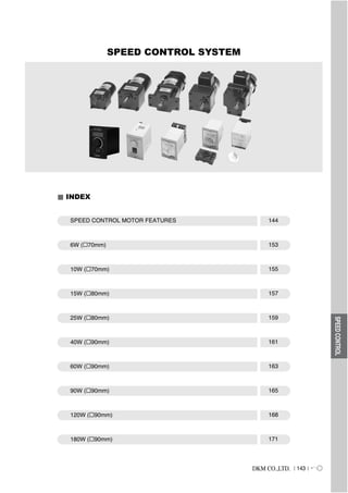
  • 1. DKM CO.,LTD. 143 SPEEDCONTROL SPEED CONTROL SYSTEM INDEX SPEED CONTROL MOTOR FEATURES 144 6W ( 70mm) 153 10W ( 70mm) 155 15W ( 80mm) 157 25W ( 80mm) 159 40W ( 90mm) 161 60W ( 90mm) 163 90W ( 90mm) 165 120W ( 90mm) 168 180W ( 90mm) 171
  • 2. 144 DKM CO.,LTD. DKM Motor allow you to easily set and adjust the speed. DKM Motor offers three kinds of AC speed control as shown below. Select the best system depending upon your application. DIGITAL TYPE (CONNECTOR Type / Digital Display) FX1000A Series UNIT TYPE (CONNECTOR Type) DSA Series SOCKET TYPE DSK Series Features of Speed Control Motor DSK Controller DSKS Controller
  • 3. DKM CO.,LTD. 145 Speed-Torque Characteristics of Speed Control Systems The speed-torque characteristics line of all AC speed control motors characteristics is shown in the figure below. Each set speed changes slightly according to the change in load torque. Safe Operation Line and Permissible Torque When Using a Gearhead Input power to the speed control motor depends on the load and speed. The greater the load, and the lower the speed, the greater an increase in motor temperature.In the speed-torque characteristics graph, the line is referred to as the safe operation line, while the area below the line is called the continuous operation area. The safe operation line, measured according to motor temperature, indicates its operational limit for continuous usage with the temperature. Whether the motor can be operated at a specific torque and speed is determined by measuring the temperature of the motor case. In general, if the motor's case temperature is below 90 (194 ), continuous operation is possible, considering the insulation class of motor coil winding. But the motor life could be extended with lower motor temperature. So it is recommended that the motor be used under conditions that keep the motor temperature low. DKM has two kinds of cooling fan ; General fna (F type) and Powerful fan (F2 type). F fan is attached in motor shaft and its speed depends on the motor shaft speed. So in slow speed of motor, there is very weak cooling effect. In the application where motor speed should be changed from low speed (below 1,000 rpm) to hight speed like speed control motor, F2 fan is needed so that cooling effect keep constantly regardless of the motor speed. In case of speed control motor and inverter motor, DKM is employing F2 type fan into them basically. ; In special application or by user s request F type fan can be employed in speed control motor and inverter motor. And please be advised that in all motors, F2 fan can be attached by user s request. SPEEDCONTROL Technical Reference Speed Control Methods of Speed Control Systems By a potentiometer, the speed setting voltage is supplied. The motors speed is sensed and the speed signal voltage is supplied. The difference between the speed setting voltage and speed signal voltage is supplied. A voltage determined by the output from the capacitor is supplied to the motor so that it will reach the set speed.
  • 4. 145-1 DKM CO.,LTD. The FX1000A series combines a control unit and AC speed Control motor. Connection between the motor and control Unit is simplified by an easy-to-use connector. Digital Type Speed Control Motor FX1000A control system Features Easy Connection Control units combine the control pack, potentiometer and capacitor into one device. Operation is possible just by connecting the control unit into power supply after connecting the motor and control unit together using the connector. Easy Operation The speed can be set easily with the potentiometer on the front panel of the control unit. DIGIRAL DISPLAY The motor speed can see directly on the front panel of display of the control unit. System Configuration Extension Cables (Accessories) ( Page 236 ) Clutch & Brake Motor Mounting Plate (Accessories) ( Page 234) FX1000A Controller Capacitor AC Power Supply Worm solid type Worm hollow type
  • 5. DKM CO.,LTD. 145-2 SPEEDCONTROL Item Detail Rated Input Voltage 220 VAC 50/60 Hz Workable Voltage from -15% to +10% of 220VAC Consumption Power Less than 4VA Control Mode Phase Loop Control (0 to 220 VAC) Input Frequency 10Hz ~ 360Hz (TACHO) Power On-Off Signal Red color of LED Speed Set Range 100 ~ 1750(RPM) Ambient Temperature from -10 to +55 Ambient Humidity 35 ~ 85% RH Weight 300g Dimension 60(w) x 100(h) x 92(d) mm Insulation Resistance 100 or more when 500V mega is applied between the windings and the housing after rated motor operation under normal ambient temperature and humidity Dielectric Strenght Sufficient to withstand 1.5KV at 50/60Hz applied between the windings and the case after rated motor operation under normal ambient temperature and humidity for 1min. Measurement CAT III FX1000A Controller Specification General Specification Motor capacity / Rated Current Specification Output Capacitor Rated Current 7SDGC - 6G 6W 0.7uF 0.15A 7SDGC - 10G 10W 1.0uF 0.18A 8SDGC - 15G 15W 1.5uF 0.26A 8SDGC - 25G 25W 2.0uF 0.32A 9SDGC - 40G 40W 2.5uF 0.47A 9SDGC - 60F2P 60W 4.0uF 0.63A 9SDGC - 90F2P 90W 5.0uF 1.05A 9SDGC - 120F2P 120W 6.0uF 1.2A 9SDGC - 180F2P 180W 6.5uF 1.6A
  • 7. DKM CO.,LTD. 145-4 Terminal Type No Fan Powerful Fan (CAPACITOR) (CAPACITOR) Connector Type Operation Method : At first connect each terminal on the rear panel of the controller with the motor as instructed in connection diagram. And then input the external power to both of the terminal AC for the rated speed operation. Now you can adjust the main volume on the center of front panel to control the output speed of motor as user want. * Direction : CW : (CW+COM) CCW : (CCW+COM) * Capacitor : Connect (9-6) or (9-3) According to it s capacity * CW : (COM+CW) * CCW : (COM+CCW) 200 - 240 V a.c 50 - 60 Hz 4VA ! 0.7uF - 2.5uF (CAPACITOR) 4.0uF - 8.0uF (CAPACITOR)
  • 8.
  • 9. DKM CO.,LTD. 147 The DSK control system combines a control unit and AC speed control motor. Connection between the motor and control unit is simplified by socket. Socket Type Speed Control Motor DSK control system Features Compact Speed Control Pack It is compact speed control pack with small pulg-in (8 pin) type. Easy Operation The speed can be set easily with the potentiometer on the front panel of DSK model. In case of DSKS model, the potentiometer (speed control volume) could be separated from body. System Configuration 1. DSK controller The variable resistor for speed control is installed in front of body like below Motor Gearhead Capacitor Socket AC Power Supply DSK Controller 2. DSKS controller The remote speed control is available by separate variable resistor like below. Motor Gearhead Capacitor Potentiometer AC Power Supply DSKS Controller SPEEDCONTROL (DSK Controller) (DSKS Controller)
  • 10. 148 DKM CO.,LTD. DSK(S) Controller Specification General Specification Dimension (1) DSK (2) DSKS Item Detail Rated Input Voltage 220 VAC 50/60 Hz Workable Voltage from -15% to +10% of 220VAC Consumption Power Less than 4VA Control Mode Phase Loop Control (0 to 210 VAC) Power On-Off Signal Red color of LED Allowed RPM Range 90 ~ 1750 RPM Ambient Temperature from -10 to +55 Weight 160g DSK (variable resistor installed) : 58(W) x 85(H) x 91(D)mm DSKS(variable resistor separated) : 49.5(W) x 77(H) x 100(D)mm 100 or more when 500V mega is applied between the windings and the housing after rated motor operation under normal ambient temperature and humidity Sufficient to withstand 1.5KV at 50/60Hz applied between the windings and the case after rated motor operation under normal ambient temperature and humidity for 1min Insulation Resistance Dimension Dielectric Strength
  • 11. DKM CO.,LTD. 149 Connection Diagrams For CCW operation, please change Red and blue. How to Read Specifications Lead Wire Type 7SDG(S)A-6G 7SDG(S)B-6G 7SDG(S)C-6G 7SDG(S)D-6G 7SDG(S)E-6G 7SDG(S)F-6G - - - - - - 1/125 Single Phase 110 Single Phase 115 Single Phase 220 Single Phase 220 Single Phase 230 Single Phase 230 60 60 50 60 50 60 90~1700 360 36 5.04 200 20 2.80 400 40 5.60 0.25 70 432 43 6.05 240 24 3.36 480 48 6.72 360 36 5.04 200 20 2.80 400 40 5.60 432 43 6.05 240 24 3.36 480 48 6.72 360 36 5.04 200 20 2.80 400 40 5.60 0.70 73 90~1400 90~1700 90~1400 90~1700 Output HP W VAC Hz Wrpm gfcm mN.m oz-in Voltage Permissible Torque 1200rpm 90rpm Starting Torque Power Consumption Freq. A Curren t Speed Range 6 Terminal Box Type Model 7SDG -6G : Pinion Shaft Type 7SDS -6 : Round Shaft Type gfcm mN.m oz-in gfcm mN.m oz-in Maximum Output : This refers to the amount of work that can be performed in a given period of time with the combination of motor and control pack. It also expresses the maximum output that can be produced within the usage limit line on the speed-torque characteristics graph. Speed range : This refers to the range of variable speed with the combination of motor and control pack. For speed control motors, the variable speed range varies with the size of load torque. Permissible torque : This refers to the maximum torque that can be produced below the safe-operation line or the permissible torque with gearhead attached at the most commonly used speeds (1200 rpm, 90 rpm). Starting torque : This refers to the size of torque that can be produced instantaneously at motor start-up with the combination of motor and control pack. Current : This refers to the current sent into the control pack at the maximum output. SPEEDCONTROL DSK DSKS
  • 12. 150 DKM CO.,LTD. Output W Frame size mm (in.) Type Power (Voltage) Single phase 100/110/115V 200/220/230V 200/220/230V 380 V 440V Three phase Page Speed Control Motor Line-Up Lead Wire - - - Terminal box - - - - - Lead Wire - - - Terminal box - - - - - Lead Wire - - - Terminal box - - - Lead Wire - - - Terminal box - - - Lead Wire - - - Terminal box - - - Lead Wire - - - Terminal box - - - Lead Wire - - - Terminal box - - - Lead Wire - - - Terminal box - - - Lead Wire - - - - Terminal box - - - - 6 10 70(2.76) 15 25 40 60 90 120 180 80(3.15) 90(3.54) How to Read Speed-Torque Characteristics Safe-operation line The safe-operation line, measured by the motor s temperature, indicates its operational limit for continuous usage with the temperature level below the permissible maximum (In case of using a reversible motor, it is measured by 30 minutes operation.) Whether the motor can be operated continuously or not, is judged by measuring the temperature of the motor case. When the temperature of the case is below 90 (194 ), the motor is capable of continuous operation. Permissible torque when gearhead is attached : When using a gearhead, be aware that it is necessary to operate below the maximum permissible torque. If the actual torque required should exceed the maximum permissible torque, it may cause possible damage to the motor and/or may shorten its life span. General Specifications Item Specifications Insulation Resistance 100 or more when 500 VDC is applied between the windings and the frame after rated motor opeation under normal ambient temperature and humidity. Dielectric Strength Sufficient to withstand 1.5 KV at 50 Hz and 60 Hz applied between the windings and the frame for 1 minute after rated motor operation under normal ambient temperature and humidity. Temperature Rise Temperature rise of windings are 80 (144 ) or less measured by the resistance change method after rated motor operation with connecting a gearhead or equivalent heat radiation plate. [ Three-Phase 6W type : 70 (126 ) ] Insulation Class Class B [ 130 (266 ) ] Overheat Protection In single-phase 50Hz, the thermal protector is built in. (Automatic return type) In case of others, it can be built by order. Operating temperature, open : 130 5 (266 9 ) close : 82 15 (179.6 27 ) Ambient Temperture Range -10 ~ + 40 (14 ~ 104 ) (nonfreezing) Ambient Humidity 85% maximum (noncondensing) 153 155 157 159 161 163 165 168 171
  • 13. DKM CO.,LTD. 151 70mm(2.76in.) SPEED CONTROL MOTOR 6W Motor Specification Enter the gear ratio in the box ( ) within the model name. A colored background indicates gear shaft rotation in the same direction as the motor shaft ; a white background indicates rotation in the opposite direction. The speed is calculated by dividing the motor's synchronous speed (50Hz : 1500 r/min, 60 Hz : 1800 r/min) by the gear ratio. The actual speed is 2~20% less than the displayed value, depending on the size of the load. Permissible Torque When using gearhead SPEEDCONTROL6W LEAD WIRE TYPE DSKDSA Speed-Torque Characteristics Enter the Phase & Voltage code in the box( ) within the motor model name. Pinion Shaft is for attaching gearhead and Round Shaft is for using motor only. : Contains a built-in thermal protector. If a motor overheats for any reason the thermal protector opened and the motor stops. When the motor temperature Drops, the thermal protector closes and the motor restarts. Be sure to turn the motor off before inspecting. By attaching F2 FAN additionally, temperature reducing of over 10 could be available. TP Lead Wire Type 7SDG(S)A-6G 7SDG(S)B-6G 7SDG(S)C-6G 7SDG(S)D-6G 7SDG(S)E-6G 7SDG(S)F-6G - - - - - - 1/125 Single Phase 110 Single Phase 115 Single Phase 220 Single Phase 220 Single Phase 230 Single Phase 230 60 60 50 60 50 60 90~1700 500 50 7.0 300 30 4.2 400 40 5.6 0.25 2.5 250 500 50 7.0 300 30 4.2 400 40 5.6 0.15 0.7 400 90~1400 90~1700 90~1400 90~1700 Output HP W VAVAC Hz rpm gfcm mN.m oz-in Voltage Permissible Torque 1200rpm 90rpm Starting Torque Condense rFreq. Current Speed Range 6 Terminal Box Type Model 7SDG -6G : Pinion Shaft Type 7SDS -6 : Round Shaft Type gfcm mN.m oz-in gfcm mN.m oz-in TP TP TP TP TP TP 3 3.6 5 6 7.5 9 12.5 15 18 25 30 36 40 50 60 75 90 100 120 1.2 1.5 2.0 2.4 3.0 3.6 5.1 6.1 7.3 9 11 13 15 17 20 25 30 30 30 0.12 0.15 0.20 0.24 0.30 0.36 0.51 0.61 0.73 0.91 1.1 1.3 1.5 1.7 2.0 2.5 3 3 3 1.06 1.32 1.77 2.1 2.6 3.2 4.5 5.4 6.4 8.0 9.7 11.5 13.2 15 18 22 26 26 26 1.2 1.5 2.0 2.4 3.0 3.6 5.1 6.1 7.3 9 11 13 15 17 20 25 30 30 30 0.12 0.15 0.20 0.24 0.30 0.36 0.51 0.61 0.73 0.91 1.1 1.3 1.5 1.7 2.0 2.5 3 3 3 1.06 1.32 1.77 2.1 2.6 3.2 4.5 5.4 6.4 8.0 9.7 11.5 13.2 15 18 22 26 26 26 0.7 0.8 1.2 1.4 1.8 2.1 3 3.5 4.2 5.5 6.4 7.6 8.5 10 11 15 17 20 23 0.07 0.08 0.12 0.14 0.18 0.21 0.30 0.35 0.42 0.55 0.64 0.76 0.85 0.99 1.1 1.5 1.7 2.0 2.3 0.62 0.71 1.1 1.2 1.6 1.9 2.6 3.1 3.7 4.9 5.7 6.7 7.5 9 10 13 15 18 20 0.7 0.8 1.2 1.4 1.8 2.1 3 3.5 4.2 5.5 6.4 7.6 8.5 10 11 15 17 20 23 0.07 0.08 0.12 0.14 0.18 0.21 0.30 0.35 0.42 0.55 0.64 0.76 0.85 0.99 1.1 1.5 1.7 2.0 2.3 0.62 0.71 1.1 1.2 1.6 1.9 2.6 3.1 3.7 4.9 5.7 6.7 7.5 9 10 13 15 18 20 rpm 1200 90 Voltage Gear Ratio 110/115 220/230 110/115 220/230 Motor/Gearhead kgf cm N.m lb-in kgf cm N.m lb-in kgf cm N.m lb-in kgf cm N.m lb-in 7SDG -6G / 7GBD BMH 150 180 30 30 3 3 26 26 30 30 3 3 26 26 30 30 3 3 26 26 30 30 3 3 26 26
  • 14. 152 DKM CO.,LTD. * Note Above table indicates output shaft dimension made by user s request and indicates the basic dimension in factory shipping. Dimension Connection Diagrams Please refer to page 148, 151.
  • 15. DKM CO.,LTD. 153 70mm(2.76in.) SPEED CONTROL MOTOR 10W Motor Specification Enter the gear ratio in the box ( ) within the model name. A colored background indicates gear shaft rotation in the same direction as the motor shaft ; a white background indicates rotation in the opposite direction. The speed is calculated by dividing the motor's synchronous speed (50Hz : 1500 r/min, 60 Hz : 1800 r/min) by the gear ratio. The actual speed is 2~20% less than the displayed value, depending on the size of the load. Permissible Torque When using gearhead LEAD WIRE TYPE DSKDSA SPEEDCONTROL10W Enter the Phase & Voltage code in the box( ) within the motor model name. Pinion Shaft is for attaching gearhead and Round Shaft is for using motor only. : Contains a built-in thermal protector. If a motor overheats for any reason the thermal protector opened and the motor stops. When the motor temperature Drops, the thermal protector closes and the motor restarts. Be sure to turn the motor off before inspecting. By attaching F2 FAN additionally, temperature reducing of over 10 could be available. TP Lead Wire Type 7SDG(S)A-10G 7SDG(S)B-10G 7SDG(S)C-10G 7SDG(S)D-10G 7SDG(S)E-10G 7SDG(S)F-10G - - - - - - 1/75 Single Phase 110 Single Phase 115 Single Phase 220 Single Phase 220 Single Phase 230 Single Phase 230 60 60 50 60 50 60 90~1700 800 80 11.2 380 38 5.3 500 50 7.0 0.30 3.0 250 800 80 11.2 380 38 5.3 500 50 7.0 1.00 1.0 400 90~1400 90~1700 90~1400 90~1700 Output HP W gfcm mN.m oz-in Permissible Torque 1200rpm 90rpm Starting Torque 10 Terminal Box Type Model 7SDG -10G : Pinion Shaft Type 7SDS -10 : Round Shaft Type gfcm mN.m oz-in gfcm mN.m oz-in TP TP TP TP TP TP VAVAC Hz rpm Voltage Condense rFreq. Current Speed Range 3 3.6 5 6 7.5 9 12.5 15 18 25 30 36 40 50 60 75 90 100 120 1.5 1.9 2.5 3.2 4.0 4.9 6.7 8.0 9.7 13 16 23 25 30 35 40 40 40 40 0.15 0.15 0.25 0.3 0.4 0.5 0.7 0.8 1.0 1.3 1.6 2.3 2.5 3.0 3.5 4 4 4 4 1.32 1.32 2.21 2.8 3.5 4.3 5.9 7.1 8.6 11.5 14.1 20.3 22.1 26 31 35 35 35 35 1.5 1.9 2.5 3.2 4.0 4.9 6.7 8.0 9.7 13 16 23 25 30 35 40 40 40 40 0.15 0.15 0.25 0.3 0.4 0.5 0.7 0.8 1.0 1.3 1.6 2.3 2.5 3.0 3.5 4 4 4 4 1.32 1.32 2.21 2.8 3.5 4.3 5.9 7.1 8.6 11.5 14.1 20.3 22.1 26 31 35 35 35 35 1.8 2.3 3.0 3.8 4.8 5.9 8.0 9.6 11.6 15.6 19 28 30 36 40 40 40 40 40 0.18 0.18 0.30 0.4 0.5 0.6 0.8 1.0 1.2 1.6 1.9 2.8 3.0 3.6 4 4 4 4 4 1.59 2.65 3.4 4.2 5.2 5.9 8.5 10.3 13.8 17.0 24.4 26.5 32 35 35 35 35 35 35 1.1 1.3 1.8 2.2 2.7 3.3 4.6 5.5 6.6 8.2 9.9 12 14 15 18 22 27 30 36 0.11 0.13 0.2 0.2 0.3 0.3 0.5 0.6 0.7 0.8 1.0 1.2 1.4 1.5 1.8 2.2 2.7 3.0 3.6 1.0 1.1 1.6 1.9 2.4 2.9 4.1 4.9 5.8 7.2 8.7 10.6 12.4 13 16 19 24 26 32 0.85 1.0 1.4 1.7 2.1 2.6 3.5 4.3 5.1 6 8 9 10 12 14 17 21 23 28 0.09 0.10 0.14 0.2 0.2 0.3 0.4 0.4 0.5 0.6 0.8 0.9 1.0 1.2 1.4 1.7 2.1 2.3 2.8 0.8 0.9 1.2 1.5 1.9 2.3 3.1 3.8 4.5 5.7 6.8 8.1 8.8 11 12 15 19 20 25 rpm 1200 90 Voltage Gear Ratio 110/115 60Hz 220/230 60Hz 220/230 50Hz 110/115 60Hz 220/230 Motor/Gearhead kgf cm N.m lb-in kgf cm N.m lb-in kgf cm N.m lb-in kgf cm N.m lb-in kgf cm N.m lb-in 7SDG -10G/ 7GBD BMH 150 180 40 40 4 4 35 35 40 40 4 4 35 35 40 40 4 4 35 35 40 40 4 4 35 35 35 40 3.5 4 31 35
  • 16. 154 DKM CO.,LTD. Dimension * Note Above table indicates output shaft dimension made by user s request and indicates the basic dimension in factory shipping. Connection Diagrams Please refer to page 148, 151.
  • 17. DKM CO.,LTD. 155 80mm(2.76in.) SPEED CONTROL MOTOR 15W Motor Specification Lead Wire Type 8SDG(S)A-15G 8SDG(S)B-15G 8SDG(S)C-15G 8SDG(S)D-15G 8SDG(S)E-15G 8SDG(S)F-15G 8SDG(S)A-15G-T 8SDG(S)B-15G-T 8SDG(S)C-15G-T 8SDG(S)D-15G-T 8SDG(S)E-15G-T 8SDG(S)F-15G-T 1/75 Single Phase 110 Single Phase 115 Single Phase 220 Single Phase 220 Single Phase 230 Single Phase 230 60 60 50 60 50 60 90~1700 1250 125 17.5 450 45 6.3 550 55 7.7 0.42 3.5 250 1260 126 17.6 1050 105 14.7 350 35 4.9 550 55 7.7 0.26 1.5 400 1260 126 17.6 1050 105 14.7 90~1400 90~1700 90~1400 90~1700 Output HP W gfcm mN.m oz-in Permissible Torque 1200rpm 90rpm Starting Torque 10 Terminal Box Type Model 8SDG -15G : Pinion Shaft Type 8SDS -15 : Round Shaft Type gfcm mN.m oz-in gfcm mN.m oz-in TP TP TP TP TP TP Enter the gear ratio in the box ( ) within the model name. A colored background indicates gear shaft rotation in the same direction as the motor shaft ; a white background indicates rotation in the opposite direction. The speed is calculated by dividing the motor's synchronous speed (50Hz : 1500 r/min, 60 Hz : 1800 r/min) by the gear ratio. The actual speed is 2~20% less than the displayed value, depending on the size of the load. If more slow speed is needed than above value, use decimal gearhead with a gear ratio of 10:1 could be used between general gearhead and motor. Even in this case, just speed will be reduced without increase in permissible torque; the maximum permissible torque is 50kgfcm (5N.m, 44lb-in). Permissible Torque When using gearhead LEAD WIRE TYPE DSKDSA SPEEDCONTROL15W VAVAC Hz rpm Voltage CondenserFreq. Current Speed Range Enter the Phase & Voltage code in the box( ) within the motor model name. Pinion Shaft is for attaching gearhead and Round Shaft is for using motor only. : Contains a built-in thermal protector. If a motor overheats for any reason the thermal protector opened and the motor stops. When the motor temperature Drops, the thermal protector closes and the motor restarts. Be sure to turn the motor off before inspecting. By attaching F2 FAN additionally, temperature reducing of over 10 could be available. TP 3 3.6 5 6 7.5 9 12.5 15 18 25 30 36 40 50 60 75 90 100 120 150 3.0 3.6 5.1 6.1 7.6 9.1 13 15 18 23 27 33 36 41 50 50 50 50 50 50 0.3 0.36 0.51 0.61 0.76 0.91 1.30 1.50 1.80 2.3 2.7 3.3 3.6 4.1 5 5 5 5 5 5 2.6 3.2 4.5 5.4 6.7 8.0 11.5 13.2 15.9 20 24 29 32 36 44 44 44 44 44 44 2.1 2.5 3.4 4.1 5.2 6.2 8.6 10 12 16 19 22 25 28 34 42 50 50 50 50 0.21 0.25 0.34 0.41 0.52 0.62 0.86 1.0 1.2 1.6 1.9 2.2 2.5 2.8 3.4 4.2 5 5 5 5 1.9 2.2 3.0 3.6 4.6 5.5 7.6 8.8 10.6 14 17 19 22 25 30 37 44 44 44 44 3.0 3.6 5.1 6.1 7.6 9.1 13 15 18 23 27 33 36 41 50 50 50 50 50 50 0.3 0.36 0.51 0.61 0.76 0.91 1.30 1.50 1.80 2.3 2.7 3.3 3.6 4.1 5 5 5 5 5 5 2.6 3.2 4.5 5.4 6.7 8.0 11.5 13.2 15.9 20 24 29 32 36 44 44 44 44 44 44 2.6 3.1 4.3 5.1 6.4 7.7 11 13 15 19.0 23 28 31 35 42 50 50 50 50 50 0.26 0.31 0.43 0.51 0.64 0.77 1.10 1.30 1.50 1.9 2.3 2.8 3.1 3.5 4.2 5 5 5 5 5 2.30 2.7 3.8 4.5 5.7 6.8 9.4 11.5 13.2 17 20 25 27 31 37 44 44 44 44 44 1.1 1.3 1.8 2.2 2.7 3.3 4.6 5.5 6.6 8.2 9.9 12 14 15 18 22 27 30 36 45 0.11 0.13 0.18 0.22 0.27 0.33 0.46 0.55 0.66 0.82 0.99 1.2 1.4 1.5 1.8 2.2 2.7 3.0 3.6 4.5 1.0 1.1 1.6 1.9 2.4 2.9 4.1 4.9 5.8 7.2 8.7 10.6 12.4 13 16 19 24 26 32 40 0.85 1.0 1.4 1.7 2.1 2.6 3.5 4.3 5.1 6 8 9 10 12 14 17 21 23 28 35 0.09 0.10 0.14 0.17 0.21 0.26 0.35 0.43 0.51 0.64 0.77 0.92 1.0 1.2 1.4 1.7 2.1 2.3 2.8 3.5 0.8 0.9 1.2 1.5 1.9 2.3 3.1 3.8 4.5 5.7 6.8 8.1 8.8 11 12 15 19 20 25 31 rpm 1200 90 Voltage Gear Ratio 110/115 60Hz 220 60Hz 230 50Hz 230 60Hz 110/115 60Hz 220/230 50Hz Motor/Gearhead kgf cm N.m lb-in kgf cm N.m lb-in kgf cm N.m lb-in kgf cm N.m lb-in kgf cm N.m lb-in kgf cm N.m lb-in 8SDG -15G/ 8GBK BMH 180 250 300 360 50 50 50 50 5 5 5 5 44 44 44 44 50 50 50 50 5 5 5 5 44 44 44 44 50 50 50 50 5 5 5 5 44 44 44 44 50 50 50 50 5 5 5 5 44 44 44 44 50 50 50 50 5 5 5 5 44 44 44 44 42 50 50 50 4.2 5 5 5 37 44 44 44
  • 18. 156 DKM CO.,LTD. Dimension * Note Above table indicates output shaft dimension made by user s request and indicates the basic dimension in factory shipping. Connection Diagrams Please refer to page 148, 151.
  • 19. DKM CO.,LTD. 157 80mm(2.76in.) SPEED CONTROL MOTOR 25W Motor Specification Lead Wire Type 8SDG(S)A-25G 8SDG(S)B-25G 8SDG(S)C-25G 8SDG(S)D-25G 8SDG(S)E-25G 8SDG(S)F-25G 8SDG(S)A-25G-T 8SDG(S)B-25G-T 8SDG(S)C-25G-T 8SDG(S)D-25G-T 8SDG(S)E-25G-T 8SDG(S)F-25G-T 1/30 Single Phase 110 Single Phase 115 Single Phase 220 Single Phase 220 Single Phase 230 Single Phase 230 60 60 50 60 50 60 90~1700 2000 200 28.0 500 50 7.0 1050 105 14.7 0.60 6.0 250 1900 190 26.6 430 43 6.0 1300 130 18.2 430 43 6.0 870 87 12.2 0.30 2.0 400 1900 190 26.6 470 47 6.6 1300 130 18.2 430 43 6.0 90~1400 90~1700 90~1400 90~1700 Output HP W gfcm mN.m oz-in Permissible Torque 1200rpm 90rpm Starting Torque 25 Terminal Box Type Model 8SDG -25G : Pinion Shaft Type 8SDS -25 : Round Shaft Type gfcm mN.m oz-in gfcm mN.m oz-in TP TP TP TP TP TP Enter the gear ratio in the box ( ) within the model name. A colored background indicates gear shaft rotation in the same direction as the motor shaft ; a white background indicates rotation in the opposite direction. The speed is calculated by dividing the motor's synchronous speed (50Hz : 1500 r/min, 60 Hz : 1800 r/min) by the gear ratio. The actual speed is 2~20% less than the displayed value, depending on the size of the load. If more slow speed is needed than above value, use decimal gearhead with a gear ratio of 10:1 could be used between general gearhead and motor. Even in this case, just speed will be reduced without increase in permissible torque; the maximum permissible torque is 80kgfcm (8N.m, 71lb-in). Permissible Torque When using gearhead LEAD WIRE TYPE DSKDSA SPEEDCONTROL25W VAVAC Hz rpm Voltage CondenserFreq. Current Speed Range Enter the Phase & Voltage code in the box( ) within the motor model name. Pinion Shaft is for attaching gearhead and Round Shaft is for using motor only. : Contains a built-in thermal protector. If a motor overheats for any reason the thermal protector opened and the motor stops. When the motor temperature Drops, the thermal protector closes and the motor restarts. Be sure to turn the motor off before inspecting. By attaching F2 FAN additionally, temperature reducing of over 10 could be available. TP 3 3.6 5 6 7.5 9 12.5 15 18 25 30 36 40 50 60 75 90 100 120 150 4.9 5.8 8.1 9.7 12 15 20 24 29 37 44 53 58 66 79 80 80 80 80 80 0.49 0.58 0.81 0.97 1.20 1.50 2.00 2.40 2.90 3.70 4.4 5.3 5.8 6.6 7.9 8 8 8 8 8 4.33 5.12 7.2 8.6 10.6 13.2 17.7 21.2 25.6 33 39 47 51 58 70 71 71 71 71 71 3.2 3.8 5.3 6.3 7.9 9.5 13 16 19 24 28 34 39 43 51 64 77 80 80 80 0.32 0.38 0.53 0.63 0.79 0.95 1.3 1.6 1.9 2.4 2.8 3.4 3.9 4.3 5.1 6.4 7.7 8 8 8 2.8 3.4 4.7 5.6 7.0 8.4 11.5 14.1 16.8 21 25 30 34 38 45 57 68 71 71 71 4.6 5.5 7.7 9.2 12 14 19 23 28 35 42 50 57 63 75 80 80 80 80 80 0.46 0.55 0.77 0.92 1.2 1.4 1.9 2.3 2.8 3.5 4.2 5.0 5.7 6.3 7.5 8 8 8 8 8 4.06 4.86 6.8 8.1 10.6 12.4 16.8 20.3 24.7 31 37 44 50 56 66 71 71 71 71 71 1.2 1.5 2 2.4 3 3.6 5.1 6.1 7.3 9.1 11 13 15 17 20 25 30 33 40 50 0.12 0.15 0.20 0.24 0.30 0.36 0.51 0.61 0.73 0.91 1.1 1.3 1.5 1.7 2.0 2.5 3.0 3.3 4.0 5.0 1.06 1.32 1.8 2.1 2.6 3.2 4.5 5.4 6.4 8 10 11 13 15 18 22 26 29 35 44 1.0 1.3 1.7 2.1 2.6 3.1 4.4 5.2 6.3 7.8 9.4 11 13 14 17 31 26 28 34 43 0.10 0.13 0.17 0.21 0.26 0.31 0.44 0.52 0.63 0.78 0.94 1.1 1.3 1.4 1.7 3.1 2.6 2.8 3.4 4.3 0.88 1.15 1.5 1.9 2.3 2.7 3.9 4.6 5.6 6.9 8.3 9.4 11.5 12 15 19 23 25 30 38 1.1 1.4 1.9 2.3 2.9 3.4 4.8 5.7 6.9 8.6 10 12 14 16 19 23 28 31 37 47 0.11 0.14 0.19 0.23 0.29 0.34 0.48 0.57 0.69 0.86 1.0 1.2 1.4 1.6 1.9 2.3 28 3.1 3.7 4.7 0.97 1.24 1.68 2.03 2.56 3.0 4.2 5.0 6.1 7.6 8.8 10.6 12.4 14 17 20 25 27 33 42 rpm 1200 90 Voltage Gear Ratio 110/115 60Hz 220/230 60Hz 220/230 50Hz 110/115 60Hz 220/230 60Hz 220/230 50Hz Motor/Gearhead kgf cm N.m lb-in kgf cm N.m lb-in kgf cm N.m lb-in kgf cm N.m lb-in kgf cm N.m lb-in kgf cm N.m lb-in 8SDG -25G/ 8GBK BMH 180 250 300 360 80 80 80 80 8 8 8 8 71 71 71 71 80 80 80 80 8 8 8 8 71 71 71 71 80 80 80 80 8 8 8 8 71 71 71 71 59 65 80 80 5.9 6.5 8 8 52 57 71 71 51 55 75 80 5.1 5.5 7.5 8 45 49 66 71 56 65 80 80 5.6 6.5 8 8 49 57 71 71
  • 20. 158 DKM CO.,LTD. Dimension * Note Above table indicates output shaft dimension made by user s request and indicates the basic dimension in factory shipping. Connection Diagrams Please refer to page 148, 151.
  • 21. DKM CO.,LTD. 159 90mm(3.54in.) SPEED CONTROL MOTOR 40W Motor Specification Lead Wire Type 9SDG(D)A-40G 9SDG(D)B-40G 9SDG(D)C-40G 9SDG(D)D-40G 9SDG(D)E-40G 9SDG(D)F-40G 9SDG(D)A-40G-T 9SDG(D)B-40G-T 9SDG(D)C-40G-T 9SDG(D)D-40G-T 9SDG(D)E-40G-T 9SDG(D)F-40G-T 1/18 Single Phase 110 Single Phase 115 Single Phase 220 Single Phase 220 Single Phase 230 Single Phase 230 60 60 50 60 50 60 90~1700 2600 260 26.4 700 70 9.8 1800 180 25.2 0.90 10 250 3000 300 42.0 630 63 8.8 2300 230 32.2 630 63 8.8 1400 140 19.6 0.45 2.5 400 3000 300 42.0 630 63 8.8 2300 230 32.2 630 63 8.8 90~1400 90~1700 90~1400 90~1700 Output HP W gfcm mN.m oz-in Permissible Torque 1200rpm 90rpm Starting Torque 40 Terminal Box Type Model 9SDG -40G : Pinion Shaft Type 9SDD -40 : D-Cut Shaft Type gfcm mN.m oz-in gfcm mN.m oz-in TP TP TP TP TP TP Enter the gear ratio in the box ( ) within the gearhead model name. A colored background indicates gear shaft rotation in the same direction as the motor shaft ; a white background indicates rotation in the opposite direction. The speed is calculated by dividing the motor s synchronous speed (50Hz : 1500 r/min, 60 Hz : 1800 r/min) by the gear ratio. The actual speed is 2~20% less than the displayed value, depending on the size of the load. If more slow speed is needed than above value, use decimal gearhead with a gear ratio of 10:1 could be used between general gearhead and motor. Even in this case, just speed will be reduced without increase in permissible torque; the maximum permissible torque is 100kgfcm Permissible Torque When using gearhead LEAD WIRE TYPE DSKDSA SPEEDCONTROL40W VAVAC Hz rpm Voltage CondenserFreq. Current Speed Range Enter the Phase & Voltage code in the box( ) within the motor model name. Pinion Shaft is for attaching gearhead and D-Cut Shaft is for using motor only. : Contains a built-in thermal protector. If a motor overheats for any reason the thermal protector opened and the motor stops. When the motor temperature Drops, the thermal protector closes and the motor restarts. Be sure to turn the motor off before inspecting. By attaching F2 FAN additionally, temperature reducing of over 10 could be available. TP 2 3 3.6 5 6 7.5 9 10 12.5 15 18 25 30 36 40 50 60 75 90 100 5.5 6.3 7.6 11 13 16 19 23 26 32 38 47 57 68 72 86 100 100 100 100 0.55 0.63 0.76 1.10 1.3 1.6 1.9 2.3 2.6 3.2 3.8 4.87 5.7 6.8 7.2 8.6 10 10 10 10 4.9 5.6 6.7 9.7 11.5 14.1 16.8 20.3 23 28 34 42 50 60 64 76 88 88 88 88 4.5 5.6 6.7 9.3 11 14 17 19 23 28 34 42 50 60 68 76 91 100 100 100 0.45 0.56 0.67 0.93 1.1 1.4 1.7 1.9 2.3 2.8 3.4 4.2 5.0 6.0 6.8 7.6 9.1 10 10 10 4.0 4.9 5.9 8.2 9.7 12.4 15 17 20 25 30 37 44 53 60 67 80 88 88 88 6.5 7.3 8.7 12 15 18 22 25 30 36 44 55 66 79 85 99 100 100 100 100 0.65 0.73 0.87 1.20 1.5 1.8 2.2 2.5 3.0 3.6 4.4 5.5 6.6 7.9 8.5 9.9 10 10 10 10 5.7 6.4 7.7 10.6 13.2 15.9 19 22 26 32 39 49 58 70 75 87 88 88 88 88 1.5 1.7 2.0 2.8 3.4 4.3 5.1 6.1 7.1 8.5 10 13 15 18 20 23 28 35 42 46 0.15 0.17 0.20 0.28 0.34 0.43 0.51 0.61 0.71 0.85 1.0 1.3 1.5 1.8 2.0 2.3 2.8 3.5 4.2 4.6 1.3 1.5 1.8 2.5 3.0 3.8 4.5 5.4 6.3 7.5 8.8 11.5 13.2 15.9 17.7 30 25 31 37 41 1.3 1.5 1.8 2.6 3.1 3.8 4.6 5.5 6.4 7.7 9.2 11 14 17 19 21 25 30 37 42 0.13 0.15 0.18 0.26 0.31 0.38 0.46 0.55 0.64 0.77 0.92 1.1 1.4 1.7 1.9 2.1 2.5 3.1 3.7 4.2 1.15 1.32 1.59 2.3 2.7 3.4 4.1 4.9 5.7 6.8 8.1 10 12 15 17 19 22 27 33 37 rpm 1200 90 Voltage Gear Ratio 110/115 60Hz 220/230 60Hz 220/230 50Hz 110/115 60Hz 220/230 Motor/Gearhead kgf cm N.m lb-in kgf cm N.m lb-in kgf cm N.m lb-in kgf cm N.m lb-in kgf cm N.m lb-in 9SDG -40G/ 9GBK MH 120 150 180 100 100 100 10 10 10 88 88 88 100 100 100 10 10 10 88 88 88 100 100 100 10 10 10 88 88 88 55 69 83 5.5 6.9 8.3 49 61 73 50 62 75 5.0 6.2 7.5 44 55 66
  • 22. 160 DKM CO.,LTD. Dimension * Note Above table indicates output shaft dimension made by user s request and indicates the basic dimension in factory shipping. Connection Diagrams Please refer to page 148, 151.
  • 23. DKM CO.,LTD. 161 90mm(3.54in.) SPEED CONTROL MOTOR 60W Motor Specification Lead Wire Type 9SDG(D)A-60F2P 9SDG(D)B-60F2P 9SDG(D)C-60F2P 9SDG(D)D-60F2P 9SDG(D)E-60F2P 9SDG(D)F-60F2P 9SDG(D)A-60F2P-T 9SDG(D)B-60F2P-T 9SDG(D)C-60F2P-T 9SDG(D)D-60F2P-T 9SDG(D)E-60F2P-T 9SDG(D)F-60F2P-T 1/12 Single Phase 110 Single Phase 115 Single Phase 220 Single Phase 220 Single Phase 230 Single Phase 230 60 60 50 60 50 60 90~1700 4900 490 68.6 2000 200 28.0 2850 285 39.9 1.20 16 250 4900 490 68.6 1400 140 19.6 4500 450 63.0 1600 160 22.4 2400 240 33.6 0.60 4 400 4900 490 68.6 1400 140 19.6 4500 450 63.0 1600 160 22.4 90~1400 90~1700 90~1400 90~1700 Output HP W gfcm mN.m oz-in Permissible Torque 1200rpm 90rpm Starting Torque 60 Terminal Box Type Model 9SDG -60F2P : Pinion Shaft Type 9SDD -60F2 : D-Cut Shaft Type gfcm mN.m oz-in gfcm mN.m oz-in TP TP TP TP TP TP Enter the gear ratio in the box ( ) within the gearhead model name. A colored background indicates gear shaft rotation in the same direction as the motor shaft ; a white background indicates rotation in the opposite direction. The speed is calculated by dividing the motor s synchronous speed (50Hz : 1500 r/min, 60 Hz : 1800 r/min) by the gear ratio. The actual speed is 2~20% less than the displayed value, depending on the size of the load. If more slow speed is needed than above value, use decimal gearhead with a gear ratio of 10:1 could be used between general gearhead and motor. Even in this case, just speed will be reduced without increase in permissible torque; the maximum permissible torque is 200kgfcm Permissible Torque When using gearhead LEAD WIRE TYPE + F2 FAN LEAD WIRE TYPE + F2 FAN SPEEDCONTROL60W DSA DSK VAVAC Hz rpm Voltage CondenserFreq. Current Speed Range Enter the Phase & Voltage code in the box( ) within the motor model name. Pinion Shaft is for attaching gearhead and D-Cut Shaft is for using motor only. : Contains a built-in thermal protector. If a motor overheats for any reason the thermal protector opened and the motor stops. When the motor temperature Drops, the thermal protector closes and the motor restarts. Be sure to turn the motor off before inspecting. F2 FAN is basic specification for speed control motor. TP 2 3 3.6 5 6 7.5 9 12.5 15 18 20 25 30 36 40 50 60 75 90 100 10 12 14 20 24 30 36 45 54 64 70 81 97 116 132 162 194 200 200 200 1.0 1.2 1.4 2.0 2.4 3.0 3.6 4.5 5.4 6.4 7.0 8.1 9.7 11.6 13.2 16.2 19.4 20 20 20 8.8 10.6 12.4 17.7 21 26 32 40 48 57 62 72 86 102 117 143 171 177 177 177 9 11 13 18 22 27 33 41 49 59 68 74 89 107 119 149 178 199 200 200 0.9 1.1 1.3 1.8 2.2 2.7 3.3 4.1 4.9 5.9 6.8 7.4 8.9 10.7 11.9 14.9 17.8 19.9 20 20 7.9 9.7 11.5 15.9 19.4 24 29 36 43 52 60 65 79 94 105 132 157 176 177 177 10 12 14 20 24 30 36 45 54 64 70 81 97 116 132 162 194 200 200 200 1.0 1.2 1.4 2.0 2.4 3.0 3.6 4.5 5.4 6.4 7.0 8.1 9.7 11.6 13.2 16.2 19.4 20 20 20 8.8 10.6 12.4 17.7 21 26 32 40 48 57 62 72 86 102 117 143 171 177 177 177 4.7 4.9 5.8 8.1 9.7 12 15 18 22 26 30 33 40 48 53 66 79 89 106 118 0.47 0.49 0.58 0.81 0.97 1.20 1.5 1.8 2.2 2.6 3.0 3.3 4.0 4.8 5.3 6.6 7.9 8.9 10.6 11.8 4.2 4.3 5.1 7.2 8.6 10.6 13.2 15.9 19.5 23 26 29 35 42 47 58 70 79 94 104 3.7 3.9 4.7 6.5 7.8 9.7 12.0 15.0 18.0 21 24 26 32 38 43 53 63 71 85 94 0.37 0.39 0.47 0.65 0.78 0.97 1.2 1.5 1.8 2.1 2.4 2.6 3.2 3.8 4.3 5.3 6.3 7.1 8.5 9.4 3.3 3.4 4.2 5.7 6.9 8.6 10.6 13.2 15.9 19 21 23 28 34 38 47 56 63 75 83 3.0 3.4 4.1 5.7 6.8 8.5 10 13 15 18 20 23 28 33 37 46 55 62 74 83 0.3 0.34 0.41 0.57 0.68 0.85 1.0 1.3 1.5 1.8 2.0 2.3 2.8 3.3 3.7 4.6 5.5 6.2 7.4 8.3 2.6 3.0 3.6 5.0 6.0 7.5 8.8 11.5 13.2 15.9 17.7 20.3 25 29 33 41 49 55 65 73 rpm 1200 90 Voltage Gear Ratio 110/115 60Hz 220/230 60Hz 220/230 50Hz 110/115 60Hz 220/230 60Hz 220/230 50Hz Motor/Gearhead kgf cm N.m lb-in kgf cm N.m lb-in kgf cm N.m lb-in kgf cm N.m lb-in kgf cm N.m lb-in kgf cm N.m lb-in 9SDG -60P/ 9PB(F)K BH 120 150 180 200 200 200 20 20 20 177 177 177 200 200 200 20 20 20 177 177 177 200 200 200 20 20 20 177 177 177 142 177 200 14.2 17.7 20 125 156 177 113 142 170 11.3 14.2 17 100 125 150 99 124 149 9.9 12.4 14.9 87 109 132
  • 24. 162 DKM CO.,LTD. * Note Above table indicates output shaft dimension made by user s request and indicates the basic dimension in factory shipping. Dimension Connection Diagrams Please refer to page 148, 151.
  • 25. DKM CO.,LTD. 163 90mm(3.54in.) SPEED CONTROL MOTOR 90W Motor Specification Lead Wire Type 9SDG(D)A-90F2P 9SDG(D)B-90F2P 9SDG(D)C-90F2P 9SDG(D)D-90F2P 9SDG(D)E-90F2P 9SDG(D)F-90F2P 9SDG(D)A-90F2P-T 9SDG(D)B-90F2P-T 9SDG(D)C-90F2P-T 9SDG(D)D-90F2P-T 9SDG(D)E-90F2P-T 9SDG(D)F-90F2P-T 1/8 Single Phase 110 Single Phase 115 Single Phase 220 Single Phase 220 Single Phase 230 Single Phase 230 60 60 50 60 50 60 90~1700 6900 690 96.6 2000 200 28.0 4200 420 58.8 2.10 20 250 6900 690 96.6 2300 230 32.2 6300 630 88.2 2600 260 36.4 4200 420 58.8 1.00 5.0 400 6900 690 96.6 2300 230 32.2 6300 630 88.2 2600 260 36.4 90~1400 90~1700 90~1400 90~1700 Output HP W gfcm mN.m oz-in Permissible Torque 1200rpm 90rpm Starting Torque 90 Terminal Box Type Model 9SDG -90F2P(H) : Pinion Shaft Type 9SDD -90F2 : D-Cut Shaft Type gfcm mN.m oz-in gfcm mN.m oz-in TP TP TP TP TP TP VAVAC Hz rpm Voltage CondenserFreq. Current Speed Range LEAD WIRE TYPE + F2 FAN LEAD WIRE TYPE + F2 FAN DSA DSK Enter the Phase & Voltage code in the box( ) within the motor model name. Pinion Shaft is for attaching gearhead and D-Cut Shaft is for using motor only. : Contains a built-in thermal protector. If a motor overheats for any reason the thermal protector opened and the motor stops. When the motor temperature Drops, the thermal protector closes and the motor restarts. Be sure to turn the motor off before inspecting. F2 FAN is basic specification for speed control motor. TP SPEEDCONTROL90W
  • 26. 164 DKM CO.,LTD. Enter the gear ratio in the box ( ) within the gearhead model name. A colored background indicates gear shaft rotation in the same direction as the motor shaft ; a white background indicates rotation in the opposite direction. The speed is calculated by dividing the motor s synchronous speed (50Hz : 1500 r/min, 60 Hz : 1800 r/min) by the gear ratio. The actual speed is 2~20% less than the displayed value, depending on the size of the load. If more slow speed is needed than above value, use decimal gearhead with a gear ratio of 10:1 could be used between general gearhead and motor. Even in this case, just speed will be reduced without increase in permissible torque; the maximum permissible torque is 200kgfcm (P type) / 300kgfcm (H type). Permissible Torque When using gearhead 2 3 3.6 5 6 7.5 9 12.5 15 18 20 25 30 36 40 50 60 75 90 100 16 18 21 30 35 44 53 67 80 96 100 120 145 173 200 200 200 200 200 200 1.6 1.8 2.1 3.0 3.5 4.4 5.3 6.7 8.0 9.6 10.0 12.0 14.5 17.3 20 20 20 20 20 20 14.4 15.9 18.5 26 31 39 47 59 71 85 88 106 128 153 177 177 177 177 177 177 4.5 4.9 58 8.1 9.7 12 15 18 22 26 30 33 40 48 53 66 79 89 106 118 0.45 0.49 0.58 0.81 0.97 1.2 1.5 1.8 2.2 2.6 3.0 3.3 4.0 4.8 5.3 6.6 7.9 8.9 10.6 11.8 4.0 4.3 5.1 7.2 8.6 10.6 12 16 19 23 26 29 35 42 47 58 70 79 94 104 6.0 6.3 7.6 11 13 16 19 24 28 34 40 43 51 62 70 86 103 115 138 153 0.60 0.63 0.76 1.10 1.3 1.6 1.9 2.4 2.8 3.4 4.0 4.3 5.1 6.2 7.0 8.6 10.3 11.5 13.8 15.3 5.30 5.56 6.71 9.7 11.5 14.1 16.8 21 25 30 35 38 45 55 62 76 91 102 122 135 5.2 5.6 6.7 9.3 11 14 17 21 25 30 35 38 46 55 60 76 91 102 122 136 0.52 0.56 0.67 0.93 1.1 1.4 1.7 2.1 2.5 3.0 3.5 3.8 4.6 5.5 6.0 7.6 9.1 10.2 12.2 13.6 4.59 4.94 5.92 8.2 9.7 12.4 15 19 22 26 31 34 41 49 53 67 80 90 108 120 - - - - - - - - - - - - - - 200 241 289 300 300 300 - - - - - - - - - - - - - - 20 24.1 28.9 30 30 30 - - - - - - - - - - - - - - 177 213 255 265 265 265 - - - - - - - - - - - - - - 50 66 79 89 106 118 - - - - - - - - - - - - - - 5.0 6.6 7.9 8.9 10.6 11.8 - - - - - - - - - - - - - - 44 58 70 79 94 104 - - - - - - - - - - - - - - 60 86 103 115 138 153 - - - - - - - - - - - - - - 6.0 8.6 10.3 11.5 13.8 15.3 - - - - - - - - - - - - - - 53 76 91 102 122 135 - - - - - - - - - - - - - 55 76 91 102 122 136 - - - - - - - - - - - - - - 5.5 7.6 9.1 10.2 12.2 13.6 - - - - - - - - - - - - - - 49 67 80 90 108 120 7SDG -6G / 7GBD - BMH 1200rpm 90rpm rpm / Voltage Gear Ratio 110/115 60Hz 220/230 60Hz 220/230 50Hz 1200rpm 90rpm 110/115 60Hz 220/230 60Hz 220/230 50Hz Motor/Gearhead kgf cm N.m lb-in kgf cm N.m lb-in kgf cm N.m lb-in kgf cm N.m lb-in kgf cm N.m lb-in kgf cm N.m lb-in kgf cm N.m lb-in kgf cm N.m lb-in 9SDG -90FP/ 9PB(F)K BH 9SDG -90FH/ 9HBK BH 120 150 180 200 200 200 20 20 20 177 177 177 142 177 200 14.2 17.7 20 125 156 177 184 200 200 18.4 20 20 162 177 177 163 200 200 16.3 20 20 144 177 177 300 300 300 30 30 30 265 265 266 142 177 212 14.2 17.7 21.2 125 156 187 184 230 276 18.4 23 27.6 162 203 244 163 204 244 16.3 20.4 24.4 144 180 215
  • 27. DKM CO.,LTD. 165 Dimension * Note Above table indicates output shaft dimension made by user s request and indicates the basic dimension in factory shipping. Connection Diagrams Please refer to page 148, 151. SPEEDCONTROL90W
  • 28. 166 DKM CO.,LTD. 90mm(3.54in.) SPEED CONTROL MOTOR 120W Motor Specification Lead Wire Type 9SDG(D)A-120F2P(H) 9SDG(D)B-120F2P(H) 9SDG(D)C-120F2P(H) 9SDG(D)D-120F2P(H) 9SDG(D)E-120F2P(H) 9SDG(D)F-120F2P(H) 9SDG(D)A-120F2P(H)-T 9SDG(D)B-120F2P(H)-T 9SDG(D)C-120F2P(H)-T 9SDG(D)D-120F2P(H)-T 9SDG(D)E-120F2P(H)-T 9SDG(D)F-120F2P(H)-T 1/6 Single Phase 110 Single Phase 115 Single Phase 220 Single Phase 220 Single Phase 230 Single Phase 230 60 60 50 60 50 60 90~1700 7200 720 100.8 2400 240 33.6 5400 540 75.6 2.50 25.0 250 7200 720 100.8 2800 280 39.2 7000 700 98.0 3000 300 42.0 5400 540 75.6 1.20 6.0 400 7200 720 100.8 2800 280 39.2 7000 700 98.0 3000 300 42.0 90~1400 90~1700 90~1400 90~1700 Output HP W gfcm mN.m oz-in Permissible Torque 1200rpm 90rpm Starting Torque 120 Terminal Box Type Model 9SDG -120F2P(H) : Pinion Shaft Type 9SDD -120F2 : D-Cut Shaft Type gfcm mN.m oz-in gfcm mN.m oz-in TP TP TP TP TP TP VAVAC Hz rpm Voltage CondenserFreq. Current Speed Range LEAD WIRE TYPE + F2 FAN LEAD WIRE TYPE + F2 FAN DSA DSK Enter the Phase & Voltage code in the box( ) within the motor model name. Pinion Shaft is for attaching gearhead and D-Cut Shaft is for using motor only. : Contains a built-in thermal protector. If a motor overheats for any reason the thermal protector opened and the motor stops. When the motor temperature Drops, the thermal protector closes and the motor restarts. Be sure to turn the motor off before inspecting. F2 FAN is basic specification for speed control motor. TP
  • 29. DKM CO.,LTD. 167 Enter the gear ratio in the box ( ) within the gearhead model name. A colored background indicates gear shaft rotation in the same direction as the motor shaft ; a white background indicates rotation in the opposite direction. The speed is calculated by dividing the motor s synchronous speed (50Hz : 1500 r/min, 60 Hz : 1800 r/min) by the gear ratio. The actual speed is 2~20% less than the displayed value, depending on the size of the load. If more slow speed is needed than above value, use decimal gearhead with a gear ratio of 10:1 between gearhead and motor. Even decimal gearhead is used, just speed will be reduced without increase in permissible torque ; the maximum permissible torque is 200kgfcm (P type) / 300kgfcm (H type). Permissible Torque When using gearhead 2 3 3.6 5 6 7.5 9 12.5 15 18 20 25 30 36 40 50 60 75 90 100 15 19 23 31 38 47 56 71 84 101 110 126 152 182 200 200 200 200 200 200 1.5 1.9 2.3 3.1 3.8 4.7 5.6 7.1 8.4 10.1 11 12.6 15.2 18.2 20 20 20 20 20 20 13.2 16.8 20.3 27 34 42 49 63 74 89 97 111 134 161 177 177 177 177 177 177 4.1 5.1 6.4 8.4 11 13 16 19 24 27 30 35 43 51 56 66 80 90 106 118 0.41 0.51 0.64 0.84 1.06 1.27 1.57 1.9 2.4 2.7 3.0 3.5 4.3 5.1 5.6 6.6 8 9 11 12 3.6 4.5 5.7 7.4 9.4 11.2 14 17 21 24 26 31 38 45 49 58 71 79 94 104 5.3 6.7 8.3 11 14 17 20 26 29 35 39 45 53 66 72 86 104 116 138 154 0.53 0.67 0.83 1.15 1.41 1.69 2.02 2.6 2.9 3.5 3.9 4.5 5.3 6.6 8.2 8.6 10.4 11.6 13.8 15.4 4.64 5.87 7.31 10.1 12.4 14.9 17.8 23 26 31 34 40 47 58 64 76 92 102 122 136 4.7 5.9 7.4 10 12 15 18 22 26 31 34 40 49 58 64 76 92 102 122 136 0.47 0.59 0.74 0.96 1.18 1.50 1.79 2.2 2.6 3.1 3.4 4.0 4.9 5.8 6.4 7.6 9.2 10 12 14 4.11 4.20 6.50 8.5 10.4 13.3 16 19 23 28 30 36 43 51 57 67 81 90 108 120 - 21 25 - 42 - 62 78 92 111 - 139 167 200 - 260 300 300 300 300 - 2.1 2.5 - 4.2 - 6.2 7.8 9.2 11.1 - 13.9 16.7 20.0 - 26 30 30 30 30 - 18.5 22.3 - 37 - 54 69 82 98 - 122 148 177 - 230 265 265 265 265 - 5.1 6.4 - 11 - 16 19 24 27 - 35 43 51 - 66 80 90 110 120 - 0.51 0.64 - 1.06 - 1.57 1.9 2.4 2.7 - 3.5 4.3 5.1 - 6.6 8.0 9.0 11 12 - 4.5 5.7 - 9.4 - 14 17 21 24 - 31 38 45 - 58 71 79 97 106 - 6.7 8.3 - 14 - 20 26 29 35 - 45 53 66 - 86 104 116 138 154 - 0.67 0.83 - 1.41 - 2.02 2.6 2.9 3.5 - 4.5 5.3 6.6 - 8.6 10.4 11.6 13.8 15.4 - 8.57 7.31 - 12.4 - 17.8 23 26 31 - 40 47 58 - 76 92 102 122 136 - 5.9 7.4 - 12 - 18 22 26 31 - 40 49 58 - 76 92 100 120 140 - 0.59 0.74 - 1.18 - 1.79 2.2 2.6 3.1 - 4.0 4.9 5.8 - 7.6 9.2 10 12 14 - 5.20 6.50 - 10.4 - 16 19 23 28 - 36 43 51 - 67 81 88 106 124 7SDG -6G / 7GBD - BMH 1200rpm 90rpm rpm / Voltage Gear Ratio 110/115 60Hz 220/230 60Hz 220/230 50Hz 1200rpm 90rpm 110/115 60Hz 220/230 60Hz 220/230 50Hz Motor/Gearhead kgf cm N.m lb-in kgf cm N.m lb-in kgf cm N.m lb-in kgf cm N.m lb-in kgf cm N.m lb-in kgf cm N.m lb-in kgf cm N.m lb-in kgf cm N.m lb-in 9SDG -120FP/ 9PB(F)K BH 120 150 180 200 200 200 20 20 20 177 177 177 142 178 200 14 18 20 125 157 177 184 200 200 18.4 20 20 162 177 177 164 200 200 16 20 20 145 177 177 300 300 300 30 30 30 265 265 265 140 180 240 14 18 24 124 159 212 184 250 300 18.4 25 30 162 221 265 160 240 280 16 24 28 141 212 247 9SDG -120FH/ 9HBK BH SPEEDCONTROL120W
  • 30. 168 DKM CO.,LTD. Dimension * Note Above table indicates output shaft dimension made by user s request and indicates the basic dimension in factory shipping. Connection Diagrams Please refer to page 148, 151
  • 31. DKM CO.,LTD. 169 90mm(3.54in.) SPEED CONTROL MOTOR 180W Motor Specification Lead Wire Type 9SDG(D)C-180F2P(H) 9SDG(D)D-180F2P(H) 9SDG(D)E-180F2P(H) 9SDG(D)F-180F2P(H) 9SDG(D)C-180F2P(H)-T 9SDG(D)D-180F2P(H)-T 9SDG(D)E-180F2P(H)-T 9SDG(D)F-180F2P(H)-T 1/4 Single Phase 220 Single Phase 220 Single Phase 230 Single Phase 230 50 60 50 60 12000 1200 168 3000 300 42.0 11000 1100 154 3200 320 44.8 7000 700 98 1.40 6.5 400 12000 1200 168 3000 300 42.0 11000 1100 154 3200 320 44.8 90~1400 90~1700 90~1400 90~1700 Output HP W gfcm mN.m oz-in Permissible Torque 1200rpm 90rpm Starting Torque 180 Terminal Box Type Model 9SDG -180F2P(H) : Pinion Shaft Type 9SDD -180F2 : D-Cut Shaft Type gfcm mN.m oz-in gfcm mN.m oz-in TP TP TP TP Enter the gear ratio in the box ( ) within the gearhead model name. A colored background indicates gear shaft rotation in the same direction as the motor shaft ; a white background indicates rotation in the opposite direction. The speed is calculated by dividing the motor s synchronous speed (50Hz : 1500 r/min, 60 Hz : 1800 r/min) by the gear ratio. The actual speed is 2~20% less than the displayed value, depending on the size of the load. If more slow speed is needed than above value, use decimal gearhead with a gear ratio of 10:1 could be used between general gearhead and motor. Even in this case, just speed will be reduced without increase in permissible torque; the maximum permissible torque is 200kgfcm (P type) / 300kgfcm (H type). Permissible Torque When using gearhead VAVAC Hz rpm Voltage CondenserFreq. Current Speed Range LEAD WIRE TYPE + F2 FAN LEAD WIRE TYPE + F2 FAN DSA DSK Enter the Phase & Voltage code in the box( ) within the motor model name. Pinion Shaft is for attaching gearhead and D-Cut Shaft is for using motor only. : Contains a built-in thermal protector. If a motor overheats for any reason the thermal protector opened and the motor stops. When the motor temperature Drops, the thermal protector closes and the motor restarts. Be sure to turn the motor off before inspecting. F2 FAN is basic specification for speed control motor. TP 2 3 3.6 5 6 7.5 9 12.5 15 18 20 25 30 36 40 50 60 75 90 100 24 27 32 45 54 67 80 100 120 144 160 180 200 200 200 200 200 200 200 200 2.4 2.7 3.2 4.5 5.4 6.7 8.0 10 12.0 14.4 16 18 20 20 20 20 20 20 20 20 21.2 23.5 28.5 39 48 60 70 88 106 128 141 159 177 177 177 177 177 177 177 177 6.5 7.2 9.0 12.1 15 18 22 27 34 39 43 50 56 58 62 66 80 90 106 118 0.65 0.72 0.90 1.21 1.52 1.82 2.23 2.7 3.4 3.9 4.3 5.0 5.6 5.8 6.2 6.6 8 9 11 12 5.7 6.3 8.0 10.6 13.4 16.1 20 24 30 34 38 44 49 51 55 58 71 79 94 404 8.4 9.3 11.6 17 20 24 29 36 42 51 56 65 70 72 80 86 104 116 138 154 0.84 0.93 1.16 1.65 2.00 2.43 2.84 3.6 4.2 5.1 5.6 6.5 7.0 7.2 8.0 8.6 10.4 11.6 13.8 15.4 7.42 8.22 10.3 14.6 17.7 21.4 25.4 32 37 45 49 57 62 64 71 76 92 102 122 136 7.4 8.2 10.3 14 17 22 26 31 37 45 50 57 64 64 70 76 92 102 122 136 0.74 0.82 1.03 1.38 1.68 2.16 2.55 3.1 3.7 4.5 5.0 5.7 6.4 6.4 7.0 7.6 9.2 10 12 14 6.57 7.28 9.13 12.2 14.8 19.1 23 27 33 40 44 51 57 57 62 67 81 90 108 120 - 28 34 - 57 - 84 105 126 152 - 189 227 273 - 300 300 300 300 300 - 2.8 3.4 - 5.7 - 8.4 10.5 12.6 15.2 - 18.9 22.7 27.3 - 30 30 30 30 30 - 24.7 30.0 - 50 - 74 93 111 134 - 167 200 241 - 265 265 265 265 265 - 7.2 9.0 - 15 - 22 27 34 39 - 50 56 56 - 66 80 90 110 120 - 0.72 0.90 - 1.52 - 2.23 2.7 3.4 3.9 - 5.0 5.6 5.6 - 6.6 8.0 9.0 11 12 - 6.3 8.0 - 13.4 - 20 24 30 34 - 44 49 49 - 58 71 79 97 106 - 9.3 11.6 - 20 - 29 36 42 51 - 65 70 72 - 86 104 116 138 154 - 0.93 1.16 - 2.00 - 2.87 3.6 4.2 5.1 - 6.5 7.0 7.2 - 8.6 10.4 11.6 13.8 15.4 - 8.22 10.3 - 17.7 - 25.4 32 37 45 - 57 62 64 - 76 92 102 122 136 - 8.2 10.3 - 17 - 26 31 37 45 - 57 64 64 - 76 92 100 120 140 - 0.82 1.03 - 1.68 - 2.55 3.1 3.7 4.5 - 5.7 3.4 6.4 - 7.6 9.2 10 12 14 - 7.28 9.13 - 14.8 - 23 27 33 40 - 51 57 57 - 67 81 88 106 124 7SDG -6G / 7GBD - BMH 1200rpm 90rpm rpm / Voltage Gear Ratio 110/115 60Hz 220/230 60Hz 220/230 50Hz 1200rpm 90rpm 110/115 60Hz 220/230 60Hz 220/230 50Hz Motor/Gearhead kgf cm N.m lb-in kgf cm N.m lb-in kgf cm N.m lb-in kgf cm N.m lb-in kgf cm N.m lb-in kgf cm N.m lb-in kgf cm N.m lb-in kgf cm N.m lb-in 9SDG -180FP/ 9PB(F)K BH 120 150 180 200 200 200 20 20 20 177 177 177 142 178 200 14 18 20 125 157 177 184 200 200 18.4 20 20 162 177 177 164 200 200 16 20 20 145 177 177 300 300 300 30 30 30 265 265 265 140 180 240 14 18 24 124 159 212 184 250 300 18.4 25 30 162 221 265 160 240 280 16 24 28 141 212 247 9SDG -180FH/ 9HBK BH SPEEDCONTROL180W
  • 32. 170 DKM CO.,LTD. Dimension * Note Above table indicates output shaft dimension made by user s request and indicates the basic dimension in factory shipping. Connection Diagrams Please refer to page 148, 151.