Download to read offline
![Zareena Begum et al. Int. Journal of Engineering Research and Applications www.ijera.com
ISSN: 2248-9622, Vol. 5, Issue 7, (Part - 3) July 2015, pp.40-45
www.ijera.com 45 | P a g e
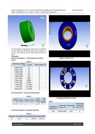
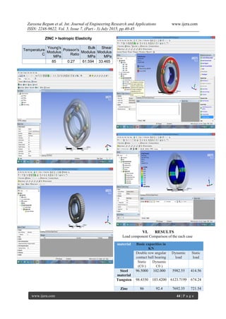
Graph 1fatigue nature
The above graph shows how the fatigue nature
change in different load condition
CONCLUSION
The Project says that how the Load vary with
the material and load acting on the bearings under
fatigue nature of the material. The fatigue nature of
the Zinc alloy is more compared to the steel &
Tungsten but comprise of highly qualified design
REFERENCES
[1.] Eschmann et al (1958) stated that when
bearings operate under normal conditions of
well balanced load and good alignment,
fatigue failure begins with small fissures.
These fissures are located between the surface
of the raceway and the rolling elements,
which then gradually propagate to the
surface, generating detectable vibrations and
increasing noise levels.
[2.] Riddle (1955) observed the fatigue
phenomena, known as flaking or spalling and
suggested that continued stress causes
fragments of the material to break or loose,
and produce a localized fatigue.
[3.] Eschmann et al (1958). Eventually, the failure
results in rough running of the bearing. This
is the initiation of failure in rolling element
bearings which reduce the life of the bearing.
According to Riddle (1995) external sources
include contamination and corrosion.
[4.] Bertele (1990) and Neale (1985) suggested
that practically an application of condition
monitoring techniques may help in early fault
detection. In their study on 23 hydrodynamic
lubrication regime occurring in rolling
bearing, high contact pressures are developed
in the surfaces to deform elastically, giving
room for small elliptical contact areas.
[5.] Mitroviü and Tatjana Lazoviü (2002)
investigated upon the frictional sliding which
follows rolling of balls along the rings
raceways. This one causes rolling bearing to
wear
[6.] Tomimoto (2003) taking a keen interest in
plain bearings, opined that an increase in
contaminant concentration could decrease the
thickness of the oil film. Larger size particles
have greater tendency to cause early fatigue
spalling in the contact zone. Besides spalling,
contaminant particles can lead to other
damage mechanisms, such as scuffing. They
originate from the lubricant starvation at the
inlet of the contact zone.
[7.] Aktürk (1999) simulated the effect of
bearings surface waviness on the vibration by
a computer program. 25 The results are
obtained in both time domain and frequency
domains. Loparo et al (2000) presented a
model-based technique for the detection of
faults. Jang and Jeong (2003) proposed an
analytical method to investigate the stability
of a rotating system due to ball bearing
waviness
[8.] Ilonen (2005) introduced a generic condition
diagnosis tool. The tool successfully detected
bearing damage in induction motors using
measurements of the stator current or
vibration. It is based on discriminative energy
functions that reveal discriminative
frequency-domain regions where failures can
be identified.
[9.] Yhland (1992) proposed a linear model for
the vibrations of the shaft bearing system
caused by ball bearing geometric
imperfections. These imperfections covered
are radial and axial waviness of outer and
inner rings, ball waviness, and ball diameter
oversize.
[10.] Tandon and Nakra (1993) reported visual
inspection of the time history of the vibration
signals, time wave form indices, probability
density function, and probability density
moments that are easily analyzed using the
time domain analysis. A time wave form
index is a single number calculated, based on
the raw vibration signal and used for trending
and comparisons. The indices include peak
value, mean value, rms value, and peak-to-
peak amplitude. This method has been
applied with only limited success for the
detection of the defects.](https://image.slidesharecdn.com/i57034045-150803071001-lva1-app6891/85/Break-Down-Analysis-of-Bearing-6-320.jpg)

This research investigates the failure of agricultural machine bearings under regular usage, proposing new models through material changes and design adjustments to enhance their durability. It employs analytical and technical methods for design and breakdown analysis using CATIA for modeling and ANSYS for simulation. The findings highlight that bearing performance varies significantly with different materials, with zinc alloys demonstrating a higher fatigue nature compared to steel and tungsten.


