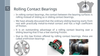
Rolling Contact Bearings
›In rolling contact bearings, the contact between the bearing surfaces is
rolling instead of sliding as in sliding contact bearings.
› We have already discussed that the ordinary sliding bearing starts from
rest with practically metal-to-metal contact and has a high coefficient
of friction.
› It is an outstanding advantage of a rolling contact bearing over a
sliding bearing that it has a low starting friction.
› Due to this low friction offered by rolling contact bearings, these are
called antifriction bearings
3.
Advantages and Disadvantagesof Rolling Contact
Bearings Over Sliding Contact Bearings
Advantages
1. Low starting and running friction
except at very high speeds.
2. Ability to withstand momentary
shock loads.
3. Accuracy of shaft alignment.
4. Low cost of maintenance, as no
lubrication is required while in
service.
5. Small overall dimensions.
6. Reliability of service.
7. Easy to mount and erect.
Disadvantages
1. More noisy at very high speeds.
2. Low resistance to shock loading.
3. More initial cost.
4. Design of bearing housing
complicated.
4.
Types of RollingContact Bearings
Following are the two types of rolling contact bearings:
1. Ball bearings; and 2. Roller bearings.
The ball and roller bearings consist of an inner race which is mounted on the
shaft or journal and an outer race which is carried by the housing or casing.
In between the inner and outer race, there are balls or rollers. A number of
balls or rollers are used and these are held at proper distances by retainers so
that they do not touch each other.
The retainers are thin strips and is usually in two parts which are assembled
after the balls have been properly spaced.
The ball bearings are used for light loads and the roller bearings are used for
heavier loads.
The rolling contact bearings, depending upon the load to be carried, are
classified as :
(a) Radial bearings, and (b) Thrust bearings.
5.
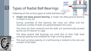
Types of RadialBall Bearings
Following are the various types of radial ball bearings:
1. Single row deep groove bearing. A single row deep groove bearing
is shown in Fig. (a).
During assembly of this bearing, the races are offset and the
maximum number of balls are placed between the races.
The races are then centered and the balls are symmetrically located
by the use of retainer or cage.
The deep groove ball bearings are used due to their high load
carrying capacity and suitability for high running speeds.
The load carrying capacity of a ball bearing is related to the size and
number of the balls.
6.
Cont.
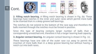
2. Filling notchbearing. A filling notch bearing is shown in Fig. (b). These
bearings have notches in the inner and outer races which permit more balls
to be inserted than in a deep groove ball bearings.
The notches do not extend to the bottom of the race way and therefore the
balls inserted through the notches must be forced in position.
Since this type of bearing contains larger number of balls than a
corresponding unnotched one, therefore it has a larger bearing load capacity.
3. Angular contact bearing. An angular contact bearing is shown in Fig. (c).
These bearings have one side of the outer race cut away to permit the
insertion of more balls than in a deep groove bearing but without having a
notch cut into both races.
7.
Cont.
This permits thebearing to carry a relatival large axial load in one
direction while also carrying a relatively large radial load.
The angular contact bearings are usually used in pairs so that thrust
loads may be carried in either direction.
4. Double row bearing. These bearings may be made with radial or
angular contact between the balls and races.
The double row bearing is appreciable narrower than two single row
bearings.
The load capacity of such bearings is slightly less than twice that of a
single row bearing. surface.
Consequently, the outer race may be displaced through a small angle
without interfering with the normal operation of the bearing.
The internally self-aligning ball bearing is interchangeable with other ball
bearings.
8.
Cont.
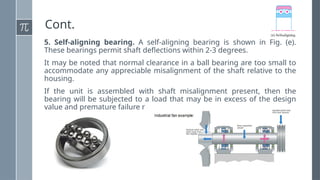
5. Self-aligning bearing.A self-aligning bearing is shown in Fig. (e).
These bearings permit shaft deflections within 2-3 degrees.
It may be noted that normal clearance in a ball bearing are too small to
accommodate any appreciable misalignment of the shaft relative to the
housing.
If the unit is assembled with shaft misalignment present, then the
bearing will be subjected to a load that may be in excess of the design
value and premature failure may occur.
9.
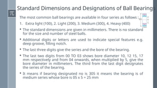
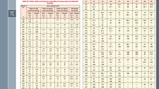
Standard Dimensions andDesignations of Ball Bearings
The most common ball bearings are available in four series as follows :
1. Extra light (100), 2. Light (200), 3. Medium (300), 4. Heavy (400)
The standard dimensions are given in millimeters. There is no standard
for the size and number of steel balls.
Additional digits or letters are used to indicate special features e.g.
deep groove, filling notch.
The last three digits give the series and the bore of the bearing.
The last two digits from 00 TO 03 shows bore diameter 10, 12 15, 17
mm respectively and from 04 onwards, when multiplied by 5, give the
bore diameter in millimeters. The third from the last digit designates
the series of the bearing.
It means if bearing designated no is 305 it means the bearing is of
medium series whose bore is 05 x 5 = 25 mm
10.
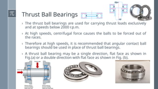
Thrust Ball Bearings
›The thrust ball bearings are used for carrying thrust loads exclusively
and at speeds below 2000 r.p.m.
› At high speeds, centrifugal force causes the balls to be forced out of
the races.
› Therefore at high speeds, it is recommended that angular contact ball
bearings should be used in place of thrust ball bearings.
› A thrust ball bearing may be a single direction, flat face as shown in
Fig.(a) or a double direction with flat face as shown in Fig. (b).
11.
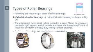
Types of RollerBearings
› Following are the principal types of roller bearings :
1. Cylindrical roller bearings. A cylindrical roller bearing is shown in Fig.
(a).
› These bearings have short rollers guided in a cage. These bearings are
relatively rigid against radial motion and have the lowest coefficient of
friction of any form of heavy duty rolling-contact bearings.
› Such type of bearings are used in high speed service.
12.
Cont.
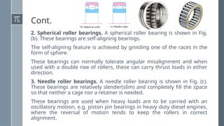
2. Spherical rollerbearings. A spherical roller bearing is shown in Fig.
(b). These bearings are self-aligning bearings.
The self-aligning feature is achieved by grinding one of the races in the
form of sphere.
These bearings can normally tolerate angular misalignment and when
used with a double row of rollers, these can carry thrust loads in either
direction.
3. Needle roller bearings. A needle roller bearing is shown in Fig. (c).
These bearings are relatively slender(slim) and completely fill the space
so that neither a cage nor a retainer is needed.
These bearings are used when heavy loads are to be carried with an
oscillatory motion, e.g. piston pin bearings in heavy duty diesel engines,
where the reversal of motion tends to keep the rollers in correct
alignment.
13.
Cont.
4. Tapered rollerbearings. A tapered roller bearing is shown in Fig. (d).
› The rollers and race ways of these bearings are truncated cones whose
elements intersect at a common point.
› Such type of bearings can carry both radial and thrust loads.
› These bearings are available in various combinations as double row
bearings and with different cone angles for use with different relative
magnitudes of radial and thrust loads.
14.
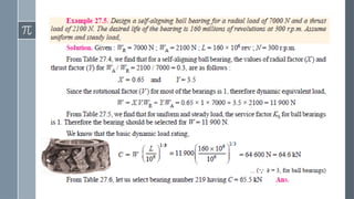
Basic Static LoadRating of Rolling Contact
Bearings
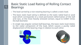
› The load carried by a non-rotating bearing is called a static load.
› The basic static load rating is defined as the static radial load or axial
load which corresponds to a total permanent deformation of the ball
and race, at the most heavily stressed contact, equal to 0.0001 times
the ball diameter.
› In single row angular contact ball bearings, the basic static load relates
to the radial component of the load, which causes a purely radial
displacement of the bearing rings in relation to each other.
15.
Cont.
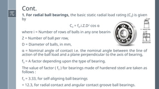
1. For radialball bearings, the basic static radial load rating (C0) is given
by
C0 = f0.i.Z.D2
cos α
where i = Number of rows of balls in any one bearing,
Z = Number of ball per row,
D = Diameter of balls, in mm,
α = Nominal angle of contact i.e. the nominal angle between the line of
action of the ball load and a plane perpendicular to the axis of bearing,
f0 = A factor depending upon the type of bearing.
The value of factor ( f0 ) for bearings made of hardened steel are taken as
follows :
f0 = 3.33, for self-aligning ball bearings
= 12.3, for radial contact and angular contact groove ball bearings.
16.
Cont.
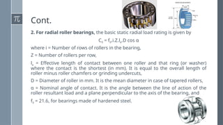
2. For radialroller bearings, the basic static radial load rating is given by
C0 = f0.i.Z.le.D cos α
where i = Number of rows of rollers in the bearing,
Z = Number of rollers per row,
le = Effective length of contact between one roller and that ring (or washer)
where the contact is the shortest (in mm). It is equal to the overall length of
roller minus roller chamfers or grinding undercuts,
D = Diameter of roller in mm. It is the mean diameter in case of tapered rollers,
α = Nominal angle of contact. It is the angle between the line of action of the
roller resultant load and a plane perpendicular to the axis of the bearing, and
f0 = 21.6, for bearings made of hardened steel.
17.
Cont.
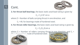
3. For thrustball bearings, the basic static axial load rating is given by
C0 = f0.Z.D2
sin α
where Z = Number of balls carrying thrust in one direction, and
f0 = 49, for bearings made of hardened steel.
4. For thrust roller bearings, the basic static axial load rating is given by
C0 = f0.Z.le.D.sin α
where Z = Number of rollers carrying thrust in one direction, and f0 =
98.1, for bearings made of hardened steel.
18.
Static Equivalent Loadfor Rolling Contact
Bearings
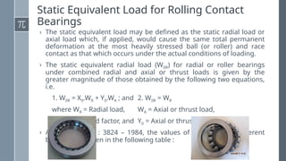
› The static equivalent load may be defined as the static radial load or
axial load which, if applied, would cause the same total permanent
deformation at the most heavily stressed ball (or roller) and race
contact as that which occurs under the actual conditions of loading.
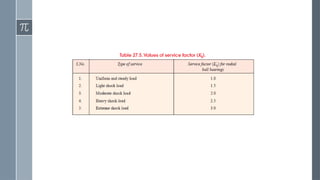
› The static equivalent radial load (W0R) for radial or roller bearings
under combined radial and axial or thrust loads is given by the
greater magnitude of those obtained by the following two equations,
i.e.
1. W0R = X0.WR + Y0.WA ; and 2. W0R = WR
where WR = Radial load, WA = Axial or thrust load,
X0 = Radial load factor, and Y0 = Axial or thrust load factor.
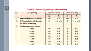
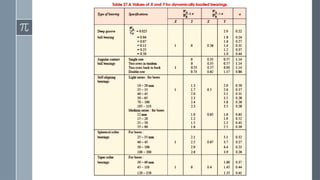
› According to IS : 3824 – 1984, the values of X0 and Y0 for different
bearings are given in the following table :
20.
Life of aBearing
› The life of an individual ball (or roller) bearing may be defined as the
number of revolutions (or hours at some given constant speed) which
the bearing runs before the first evidence of fatigue develops in the
material of one of the rings or any of the rolling elements.
› The term minimum life is also used to denote the rating life.
› It has been found that the average life of a bearing is 5 times the rating
life (or minimum life).
› It may be noted that the longest life of a single bearing is seldom
longer than the 4 times the average life and the maximum life of a
single bearing is about 30 to 50 times the minimum life.
21.
Basic Dynamic LoadRating of Rolling
Contact Bearings
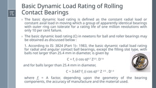
› The basic dynamic load rating is defined as the constant radial load or
constant axial load in moving which a group of apparently identical bearings
with outer ring can tolerate for a rating life of one million revolutions with
only 10 per cent failure.
› The basic dynamic load rating (C) in newtons for ball and roller bearings may
be obtained as discussed below :
1. According to IS: 3824 (Part 1)– 1983, the basic dynamic radial load rating
for radial and angular contact ball bearings, except the filling slot type, with
balls not larger than 25.4 mm in diameter, is given by
C = fc (i cos α)0.7
Z2/3
. D1.8
and for balls larger than 25.4 mm in diameter,
C = 3.647 fc (i cos α)0.7
Z 2/3
. D1.4
where fc = A factor, depending upon the geometry of the bearing
components, the accuracy of manufacture and the material used.
22.
Cont.
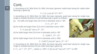
2. According toIS: 3824 (Part 2)–1983, the basic dynamic radial load rating for radial roller
bearings is given by
C = fc (i. le cos α)7/9
Z3/4
. D29/27
3. According to IS: 3824 (Part 3)–1983, the basic dynamic axial load rating for single row,
single or double direction thrust ball bearings is given as follows :
(a) For balls not larger than 25.4 mm in diameter and α = 90º,
C = fc . Z2/3
. D1.8
(b) For balls not larger than 25.4 mm in diameter and α ≠ 90º,
C = fc (cos α)0.7
tan α. Z2/3
. D1.8
(c) For balls larger than 25.4 mm in diameter and α = 90º
C = 3.647 fc . Z2/3
. D1.4
(d) For balls larger than 25.4 mm in diameter and α ≠ 90º,
C = 3.647 fc (cos α)0.7
tan α . Z2/3
. D1.4
4. According to IS: 3824 (Part 4)–1983, the basic dynamic axial load rating for single row,
single or double direction thrust roller bearings is given by
C = fc . Le 7/9
. Z3/4
. D29/27
... (when α = 90º) = fc (le cos α)7/9
tan α.Z3/4
. D29/27
α ≠ 90º
23.
Dynamic Equivalent Loadfor Rolling Contact
Bearings
› The dynamic equivalent load may be defined as the constant stationary radial
load or axial load which, if applied to a bearing with rotating inner ring and
stationary outer ring, would give the same life as that which the bearing will
attain under the actual conditions of load and rotation.
› The dynamic equivalent radial load (W) for radial and angular contact bearings,
except the filling slot types, under combined constant radial load (WR) and
constant axial or thrust load (WA) is given by
W = X . V. WR + Y . WA
where V = A rotation factor,
= 1, for all types of bearings when the inner race is rotating,
= 1, for self-aligning bearings when inner race is stationary,
= 1.2, for all types of bearings except self-aligning, when inner race is
stationary.
24.
Dynamic Load Ratingfor Rolling Contact
Bearings under Variable Loads
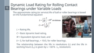
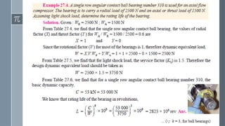
The approximate rating (or service) life of ball or roller bearings is based
on the fundamental equation
L = Rating life,
C = Basic dynamic load rating,
W = Equivalent dynamic load, and
k = 3, for ball bearings, = 10/3, for roller bearings.
The relationship between the life in revolutions (L) and the life in
working hours (LH) is given by L = 60 N . LH revolutions
25.
Materials and Manufactureof Ball and Roller
Bearings
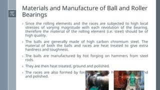
› Since the rolling elements and the races are subjected to high local
stresses of varying magnitude with each revolution of the bearing,
therefore the material of the rolling element (i.e. steel) should be of
high quality.
› The balls are generally made of high carbon chromium steel. The
material of both the balls and races are heat treated to give extra
hardness and toughness.
› The balls are manufactured by hot forging on hammers from steel
rods.
› They are then heat treated, ground and polished.
› The races are also formed by forging and then heat-treated, ground
and polished.
26.
Lubrication of Balland Roller Bearings
The ball and roller bearings are lubricated for the following purposes :
1. To reduce friction and wear between the sliding parts of the bearing,
2. To prevent rusting or corrosion of the bearing surfaces,
3. To protect the bearing surfaces from water, dirt etc., and
4. To dissipate the heat.
In general, oil or light grease is used for lubricating ball and roller
bearings. Only pure mineral oil or a calcium-base grease should be used.
If there is a possibility of moisture contact, then potassium or sodium-
base greases may be used.
Another additional advantage of the grease is that it forms a seal to keep
out dirt or any other foreign substance.
It may be noted that too much oil or grease cause the temperature of
the bearing to rise due to churning(mixing). The temperature should be
kept below 90ºC and in no case a bearing should operate above 150ºC.
Assignment 2
› Question:Write short note on classifications and different
types of antifriction bearings. And also explain where are
the angular contact and self-aligning ball bearings used
(With industrial example). CLO - I
› Be ready for Quiz 2 in upcoming week.
› Note:
› Kindly submit your assignment before 04:00 pm on 27th Jan
2020.
› Should be on A4 page.
› Assignment cover page should be on proper format.