Downloaded 24 times

![Hitesh pandey et al. Int. Journal of Engineering Research and Applications www.ijera.com
ISSN : 2248-9622, Vol. 4, Issue 11(Version - 5), November 2014, pp.60-64
www.ijera.com 61 | P a g e
1. Head or crown-The piston head or crown may be flat, convex or concave depending upon the design of combustion chamber. It withstands the pressure of gas in the cylinder. 2. Piston rings-The piston rings are used to seal the cylinder in order to prevent leakage of the gas past the piston. 3. Skirt-The skirt acts as a bearing for the side thrust of the connecting rod on the walls of cylinder. 4. Piston pin-It is also called gudgeon pin or wrist pin. It is used to connect the piston to the connecting rod. Literature Review:
A combined experimental and numerical study has been carried out on finned metal foam and metal foam heat sinks under impinging air jet cooling M.M. Haquea observed that as the superheating temperature is increased up to an optimum temperature of 750 ◦C, the eutectic silicon becomes more globular and well distributed all over the entire structure[2]. Ajay Raj Singh describes the stress distribution and thermal stresses of three different aluminum alloys piston by using finite element method (FEM)[3]. M.X. Calbureanu compare the behavior of the combustion engine piston made of aluminum alloys. The paper describes the mesh optimization with using finite element analysis technique to predict the higher stress and critical region on the component[4]. S. Srikanth Reddy investigated on a conventional (uncoated) diesel piston, made of aluminium silicon alloy for design 1 and design 2 parameters. Secondly, thermal analyses are performed on piston, coated with Zirconium material by means of using a commercial code, namely ANSYS [5]. A. R. Bhagat describes the stress distribution of the seizure on piston four stroke engine by using FEA. The finite element analysis is performed by using computer aided design (CAD) software. The main objectives are to investigate and analyze the thermal stress distribution of piston at the real engine condition during combustion process. The paper describes the mesh optimization with using finite element analysis technique to predict the higher stress and critical region on the component [6]. Vinay V. Kuppast studied the geometric three dimensional model of the piston is developed and is used for the FE analysis for the thermal boundary conditions which are calculated by using the experimental data of the engine in running condition and by using the empirical relations[7]. Yuan Shen presented a thermodynamic model of IC engine combustion is and examined. A heat release function and an empirical conversion efficiency factor are introduced to solve the model. The pressure traces obtained by solving the thermodynamic model are compared with measured pressure data for a fully instrumented laboratory IC spark ignition (SI) engine. Derived scaling parameters for time to peak pressure, peak pressure, and maximum rate of pressure rise (Among others) are developed and compared with the numerical simulations [8].
III. Methodology:
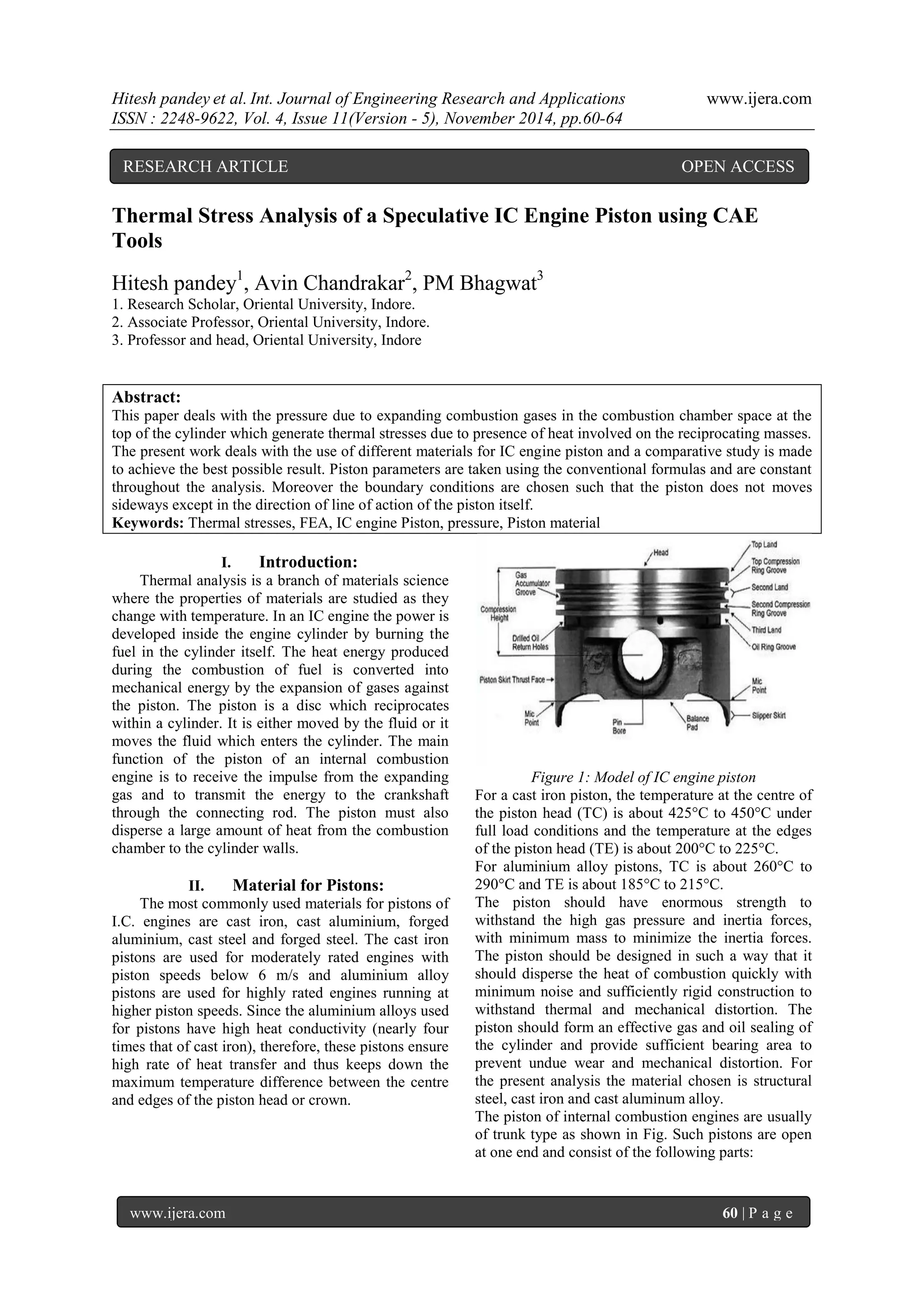
Whenever there is some increase or decrease in the temperature of a body, it causes the body to expand or contract. A little consideration will show that if the body is allowed to expand or contract freely, with the rise or fall of the temperature, no stresses are induced in the body. But, if the deformation of the body is prevented, some stresses are induced in the body. Such stresses are known as thermal stresses. [1] Let l = Original length of the body, t = Rise or fall of temperature, and α= Coefficient of thermal expansion, Thus increase or decrease in length, llt If the ends of the body are fixed to rigid supports, so that its expansion is prevented, then compressive strain induced in the body, c= 푙 푙 = 푙.α.푡 푙 =훼.푡 Thermal stress, th = c.E = .t.E The thickness of the piston head (tH), according to Grashoff’s formula is given by tH = 3푝퐷216 휎푡 12(in mm) Where p = Maximum gas pressure in N/mm2, D = Outside diameter of the piston in mm, and σt = Permissible bending (tensile) stress
IV. Radial thickness of piston rings:
t1= 퐷[ 3푃푤 휎푡 ] 12 Where D = Cylinder bore in mm, pw = Pressure of gas on the cylinder wall in N/mm2. σt = Allowable bending (tensile) stress in MPa.
V. Maximum axial thickness of piston rings:
t2= [ 퐷 10 푛푅 ] nR = Number of rings The maximum thickness (t3) of the piston barrel may be obtained from the following empirical relation: 푡3=0.03 퐷+푏+4.5 mm
Where](https://image.slidesharecdn.com/l0411056064-141212223539-conversion-gate01/85/Thermal-Stress-Analysis-of-a-Speculative-IC-Engine-Piston-using-CAE-Tools-2-320.jpg)
![Hitesh pandey et al. Int. Journal of Engineering Research and Applications www.ijera.com
ISSN : 2248-9622, Vol. 4, Issue 11(Version - 5), November 2014, pp.60-64
www.ijera.com 63 | P a g e
VI. Material Properties:
VII.
Table 1: Material Properties for Present Analysis
S.No
Piston Material
Structural Steel
Cast Iron
A2618 Aluminium Alloy
1.
Young’s modulus of elasticity
200 KN_mm2
100 KN/mm2
73.7 KN/mm2
2.
Poisson’s Ratio
0.266
0.27
0.33
3.
Density
7860kg/m3
7200 Kg/m3
2768 Kg/m3
4.
Coefficient of thermal expansion
1.17x10⁻⁵ m/ ۫ ۫ c
1.0x10⁻⁵ m/ c
2.59x10⁻⁸ m/ c
5.
Shear modulus
80 KN/mm2
45 KN/mm2
25 KN/mm2
VIII. Result and discussions:
Table 2: Effect of Thermal Stresses and Corresponding Piston Distortion using Different Piston Materials
S.No
Piston Material
Structural Steel
Cast Iron
A2618 Aluminium Alloy
1.
Maximum Thermal stress (N/m2)
1.39x10⁶ N/m2
5.93x10³ N/m2
1.15x10³ N/m2
2.
Maximum displacement (mm)
0.004 mm
3.81x10⁻⁵ mm
10.6x10⁻⁵ mm
The above table shows that the maximum thermal stress and the maximum distortion of piston are minimum for A2618 Aluminium alloy as piston material, and maximum for structural steel as piston material, while for cast iron it is lesser then structural steel but higher then A2618 Aluminium alloy. So we can conclude that the maximum thermal stress and the maximum distortion of piston in decreasing order are as follows Structural Steel > Cast Iron > A2618 Aluminium Alloy. So, it is convenient to use aluminum alloy as piston material rather than cast iron or structural steel. Since the aluminium alloys used for pistons have high heat conductivity, therefore, these pistons ensure high rate of heat transfer and thus keeps down the maximum temperature difference between the centre and edges of the piston head or crown. Other advantage is aluminium alloys are about three times lighter than cast iron, therefore, its mechanical strength is good at low temperatures, Sometimes, the pistons of aluminium alloys are coated with aluminium oxide also.
IX. Conclusion:
1. Aluminum alloy should be used as a piston material as it has minimum thermal stress and mechanical distortion in same working condition as that of cast iron and structural steel as piston material.
2. Aluminum alloys are lighter in weight thus provides good mechanical strength at low temperatures.
3. Aluminium alloys have high heat conductivity thus; high rate of heat transfer is possible between the centre and edge of the piston head.
4. Use of CAE software eliminates the human effort in determination of stress, distortion
values and so are referred as good tool for piston mechanical as well as thermal analysis. Future scope:
1. This work can be extended by using some more type of aluminum alloys as piston material such as cast aluminium, forged aluminium, cast steel and forged steel.
2. Aluminum alloys may be coated with aluminum oxides for pistons working at elevated temperatures.
References:
[1.] RS Khurmi and JK Gupta “Machine Design” Eurasia publishing house (pvt.) ltd. Ram Nagar, New Delhi - 110055, http://www.simpopdf.com, 2005
[2.] S.S. Feng et al., An experimental and numerical study of finned metal foam heat sinks under impinging air jet cooling, International Journal of Heat and Mass Transfer 77 (2014) 1063–1074.
[3.] M.M. Haque et al., “Effect of superheating temperatures on microstructure and properties of strontium modified aluminium–silicon eutectic alloy” Journal of Materials Processing Technology 162–163 (2005) 312– 316
[4.] Ajay Raj Singh et al.,, Dr. Pushpendra Kumar Sharma, “Design, Analysis and Optimization of Three Aluminum Piston Alloys Using FEA” Int. Journal of Engineering Research and Applications, ISSN : 2248-9622, Vol. 4, Issue 1 Version 3, January 2014, pp.94-102.
[5.] M.X. Calbureanu et al.,, “The finite element analysis of the thermal stress distribution of a piston head” International Journal OF Mechanics, Issue 4, Volume 7, 2013, pp- 467- 474.](https://image.slidesharecdn.com/l0411056064-141212223539-conversion-gate01/85/Thermal-Stress-Analysis-of-a-Speculative-IC-Engine-Piston-using-CAE-Tools-4-320.jpg)
![Hitesh pandey et al. Int. Journal of Engineering Research and Applications www.ijera.com
ISSN : 2248-9622, Vol. 4, Issue 11(Version - 5), November 2014, pp.60-64
www.ijera.com 64 | P a g e
[6.] S. Srikanth Reddy et al., Thermal Analysis and Optimization of I.C. Engine Piston Using Finite Element Method, International Journal of Innovative Research in Science, Engineering and Technology, Vol. 2, Issue 12, December 2013, pp 7834-7843.
[7.] A. R. Bhagat et al., Thermal Analysis And Optimization Of I.C. Engine Piston Using finite Element Method, International Journal of Modern Engineering Research (IJMER) www.ijmer.com Vol.2, Issue.4, July-Aug 2012 pp-2919-2921.
[8.] Vinay V. Kuppast et al., “Thermal Analysis of Piston for the Influence on Secondary motion”, International Journal of Engineering Research and Applications (IJERA) ISSN: 2248-9622, Vol. 3, Issue 3, May-Jun 2013, pp.1402-1407](https://image.slidesharecdn.com/l0411056064-141212223539-conversion-gate01/85/Thermal-Stress-Analysis-of-a-Speculative-IC-Engine-Piston-using-CAE-Tools-5-320.jpg)

This paper presents a thermal stress analysis of internal combustion engine pistons using different materials, including structural steel, cast iron, and aluminum alloy, to identify the most effective option. It concludes that aluminum alloy pistons exhibit the lowest thermal stress and distortion due to their high heat conductivity and lightweight nature compared to cast iron and structural steel. The research emphasizes the utility of CAE software for accurate mechanical and thermal analysis in piston design.


![[IJET V2I3-1P3] Authors:G.Siva Prasad K.Dinesh Achari E.Dileep Kumar Goud M.N...](https://cdn.slidesharecdn.com/ss_thumbnails/ijet-v2i31p3-160810100258-thumbnail.jpg?width=640&height=640&fit=bounds)


