Download as PDF, PPTX

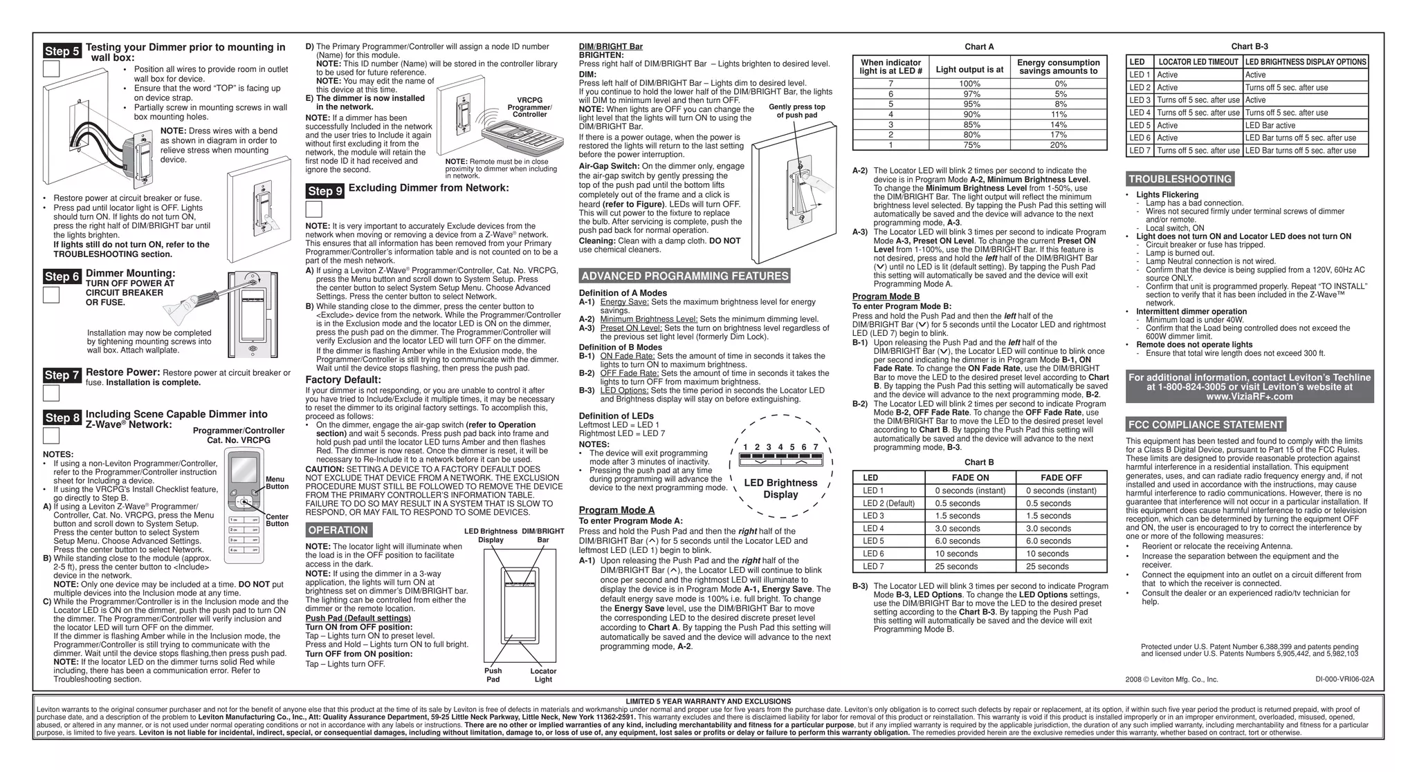

This document provides installation instructions for a single pole or 3-way scene capable incandescent dimmer. It contains warnings to only be installed according to electrical codes and by a qualified electrician. It also warns not to use the dimmer to control certain devices like fluorescent lights or motors. The instructions summarize identifying the wiring configuration, preparing the wires, and connecting the wires according to whether it is a single pole, 3-way with coordinating remote, or 3-way with matching remote installation. Diagrams illustrate the various wiring options and connection points on the dimmer and remote.