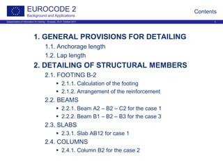
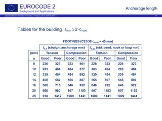
This document discusses Eurocode 2 and provides details on anchorage and lap splicing of reinforcement in slabs, columns, beams and footings according to Eurocode 2. It covers general provisions for anchorage length, including formulas and tables. It also discusses lap length, including design equations and tables providing lap length values for various bar sizes and bond conditions. The document is presented as a training material, with the contents covering anchorage length, lap splicing, and detailing of structural members like footings, beams, slabs and columns.

![Dissemination of information for training – Brussels, 20-21 October 2011 3
EUROCODE 2
Background and Applications
General provisions for detailing
Section 8 EN 1992-1-1
For ribbed reinforcement, mesh and prestressing tendons
Subjected to static loading
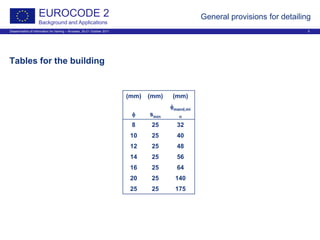
Spacing of bars [8.2]
Good concreting → adequate bond
Recom. values: K1=1,0; K2=5 mm
[ ]mm20;Kd;Kmaxs 2g1min +φ⋅=
=⇒
≤φ
=
mm25s
mm25
mm20d
if min
g
s
s](https://image.slidesharecdn.com/05ec2wsarrietadetailing-150619063117-lva1-app6891/85/05-ec2-ws_arrieta_detailing-3-320.jpg)
![Dissemination of information for training – Brussels, 20-21 October 2011 4
EUROCODE 2
Background and Applications
General provisions for detailing
Minimum diameter of the mandrel [8.3 ]
Avoid:
Bending cracks in the bar
Failure of concrete inside the bent
Conditions to avoid concrete failure [8.3 (3)]:
Either not more than 5 φ past end bend
Or bar not positioned at the edge and cross bar ≥ φ inside the bend
φm ≥ φm,min
>φφ
≤φφ
=φ
mm16if7
mm16if4
min,m
φ
φm,min](https://image.slidesharecdn.com/05ec2wsarrietadetailing-150619063117-lva1-app6891/85/05-ec2-ws_arrieta_detailing-4-320.jpg)
![Dissemination of information for training – Brussels, 20-21 October 2011 6
EUROCODE 2
Background and Applications
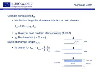
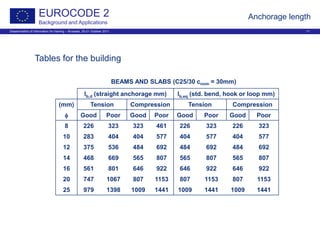
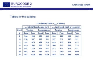
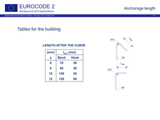
Anchorage length
Anchorage of longitudinal reinforcement [8.4]
Transmission forces reinforcement → concrete
Transverse tension stresses
Avoid:
Longitudinal cracks
Spalling
Methods:
Straight
Bend
Hook
Loop
Welded transverse bar](https://image.slidesharecdn.com/05ec2wsarrietadetailing-150619063117-lva1-app6891/85/05-ec2-ws_arrieta_detailing-6-320.jpg)
![Dissemination of information for training – Brussels, 20-21 October 2011 8
EUROCODE 2
Background and Applications
Anchorage length
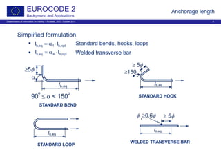
Design anchorage length [Table 8.2]
α1: Shape of bars
α2: Concrete cover
α3: Confinement by transv. reinf. not welded
α4: Confinement by welded transv. reinf.
α5: Confinement by transv. pressure
min,brqd,b54321bd lll ≥⋅α⋅α⋅α⋅α⋅α=
[ ]
=α∋φ⋅α=
ncompressioif60,0
tensionif30,0
mm100;10;lmaxl rqd,bmin,b](https://image.slidesharecdn.com/05ec2wsarrietadetailing-150619063117-lva1-app6891/85/05-ec2-ws_arrieta_detailing-8-320.jpg)
![Dissemination of information for training – Brussels, 20-21 October 2011 13
EUROCODE 2
Background and Applications
Anchorage length
Anchorage of links and shear reinf. [8.5]
BEND HOOK
WELDED TRANSVERSE REINFORCEMENT](https://image.slidesharecdn.com/05ec2wsarrietadetailing-150619063117-lva1-app6891/85/05-ec2-ws_arrieta_detailing-13-320.jpg)
![Dissemination of information for training – Brussels, 20-21 October 2011 15
EUROCODE 2
Background and Applications
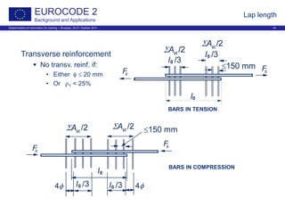
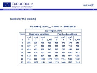
Lap length
Laps [8.7]
Transmission forces reinforcement → reinforcement
Transverse tension stresses
Avoid:
Large cracks
Spalling
Methods:
Lapping of bars
Welding
Mechanical couplers
Arrangement
Should be staggered
Not located in areas of high moments
Symmetrically at any section](https://image.slidesharecdn.com/05ec2wsarrietadetailing-150619063117-lva1-app6891/85/05-ec2-ws_arrieta_detailing-15-320.jpg)
![Dissemination of information for training – Brussels, 20-21 October 2011 16
EUROCODE 2
Background and Applications
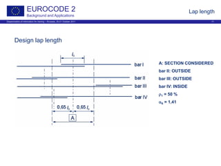
Design lap length [Table 8.2]
α1: Shape of bars
α2: Concrete cover
α3: Confinement by transv. reinf. not welded
α5: Confinement by transv. pressure
α6: Percentage of lapped bars within a zone
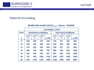
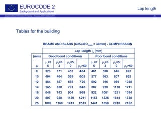
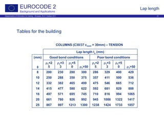
Lap length
25
1
6
ρ
=α
min,0rqd,b653210 lll ≥⋅α⋅α⋅α⋅α⋅α=
[ ]mm200;15;l30,0maxl rqd,b6min,0 φ⋅α⋅=](https://image.slidesharecdn.com/05ec2wsarrietadetailing-150619063117-lva1-app6891/85/05-ec2-ws_arrieta_detailing-16-320.jpg)
![Dissemination of information for training – Brussels, 20-21 October 2011 23
EUROCODE 2
Background and Applications
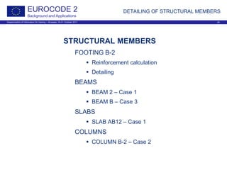
DETAILING OF STRUCTURAL MEMBERS
DETAILING OF STRUCTURAL MEMBERS [9]
Satisfy the requirements of:
Safety
Serviceability
Durability
Consistency with design models
Minimum areas of reinforcement to:
Prevent brittle failure
Prevent wide cracks
Resist forces from restrained actions
Reflections
No unique solutions
Need to simplify; usually many bars to dispose
Arrangement: complexity vs simplicity
Economics and sustainability
Aspects of cost
• Quantity of reinforcement
• Labour force
• Size of the structure](https://image.slidesharecdn.com/05ec2wsarrietadetailing-150619063117-lva1-app6891/85/05-ec2-ws_arrieta_detailing-23-320.jpg)
![Dissemination of information for training – Brussels, 20-21 October 2011 28
EUROCODE 2
Background and Applications
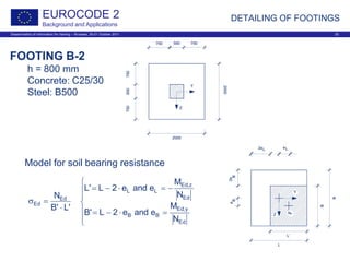
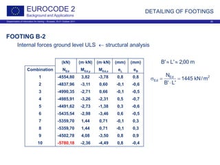
DETAILING OF FOOTINGS
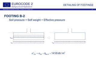
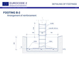
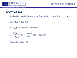
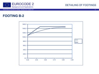
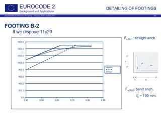
FOOTING B-2
Model for anchorage of bars [9.2.2.2]
( ) ( )
( )e
s d
i
z x
F x R x
z
= ⋅
⋅−= a35,0
2
b
FF smax,s
( )s,max sF F 0,825 1457,9 kN= =
( )7 16φ
s,max 2
s
yd
F
A 3353 mm
f
= =](https://image.slidesharecdn.com/05ec2wsarrietadetailing-150619063117-lva1-app6891/85/05-ec2-ws_arrieta_detailing-28-320.jpg)
![Dissemination of information for training – Brussels, 20-21 October 2011 33
EUROCODE 2
Background and Applications
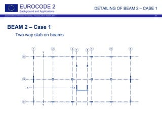
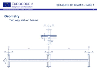
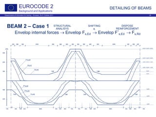
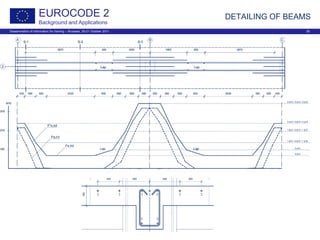
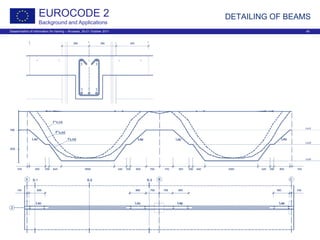
DETAILING OF BEAMS
BEAMS [9.2]
Materials
Concrete: fck = 25 N/mm2 γc = 1,50
Steel: fyk = 500 N/mm2 γs = 1,15
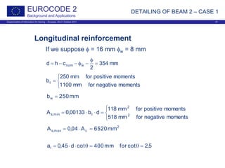
Longitudinal reinforcement
db00133,0Adb0013,0db
f
f
26,0A tmin,stt
yk
ctm
min,s ⋅⋅=⇒⋅⋅</⋅⋅⋅=
cmax,s A04,0A ⋅=
( )
2
cotcot
zal
α−θ
⋅=](https://image.slidesharecdn.com/05ec2wsarrietadetailing-150619063117-lva1-app6891/85/05-ec2-ws_arrieta_detailing-33-320.jpg)
![Dissemination of information for training – Brussels, 20-21 October 2011 34
EUROCODE 2
Background and Applications
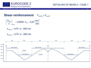
DETAILING OF BEAMS
BEAMS [9.2]
Transverse reinforcement
0008,0
f
f08,0
min,w
yk
ck
min,w =ρ⇒
⋅
=ρ
α⋅⋅
=ρ
sinbs
A
w
sw
w
w
min
sw
b0008,0
s
A
⋅=
( ) d75,0cot1d75,0s max,l ⋅=α+⋅⋅=
mm600d75,0s max,t >/⋅=](https://image.slidesharecdn.com/05ec2wsarrietadetailing-150619063117-lva1-app6891/85/05-ec2-ws_arrieta_detailing-34-320.jpg)
![Dissemination of information for training – Brussels, 20-21 October 2011 43
EUROCODE 2
Background and Applications
Detailing provisions [9.3]
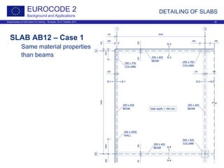
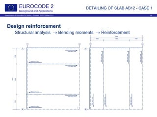
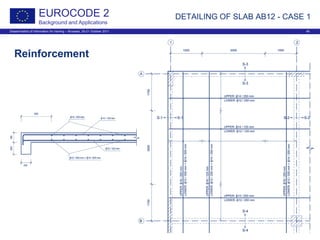
DETAILING OF SLAB AB12 - CASE 1
)mm12(mm13261230180
2
chd nom =φ=−−−=
φ
−φ−−=
mm1bt =
mm
mm
18,0db00133,0A
2
tmin,s =⋅⋅=
mm
mm
20,7A04,0A
2
cmax,s =⋅=
mm250smm250h0,2s slabsmax,slabsmax, =⇒>/⋅=
mm132dal ==](https://image.slidesharecdn.com/05ec2wsarrietadetailing-150619063117-lva1-app6891/85/05-ec2-ws_arrieta_detailing-43-320.jpg)
![Dissemination of information for training – Brussels, 20-21 October 2011 46
EUROCODE 2
Background and Applications
DETAILING OF COLUMNS
COLUMNS [9.5]
⋅
⋅
= Ac002,0;
f
N10,0
maxA
yd
Ed
min,s
cmax,s A04,0A ⋅=
φ⋅=φ longmin,t
4
1
;mm6max
[ ]mm400;b;20mins minlongmax,t φ⋅=
mm8min =φ
Longitudinal reinforcement
Transverse reinforcement
Factor 0,60:
Near beams/slab (h)
Lap length if φ>14 mm
Compression bars:
Not farer than 150 mm from a restrained bar](https://image.slidesharecdn.com/05ec2wsarrietadetailing-150619063117-lva1-app6891/85/05-ec2-ws_arrieta_detailing-46-320.jpg)
![Dissemination of information for training – Brussels, 20-21 October 2011 47
EUROCODE 2
Background and Applications
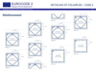
DETAILING OF COLUMN B2 – CASE 2
COLUMN B-2 – Case 2
Materials:
Concrete: fck = 25 N/mm2 γc = 1,50
Steel: fyk = 500 N/mm2 γs = 1,15
mm8min =φ
Longitudinal reinforcement
Transverse reinforcement
2
max,s mm10000A =
[ ]2
Edmin,s mm500;N23,0maxA ⋅=
>φ
φ
≤φ
=φ
mm24if
4
mm24ifmm6
long
long
long
min,t
[ ]mm400;20mins longmax,t φ⋅=](https://image.slidesharecdn.com/05ec2wsarrietadetailing-150619063117-lva1-app6891/85/05-ec2-ws_arrieta_detailing-47-320.jpg)
![Dissemination of information for training – Brussels, 20-21 October 2011 48
EUROCODE 2
Background and Applications
DETAILING OF COLUMN B2 – CASE 2
Longitudinal reinforcement
Structural analysis → As,rqd → As,disp
[mm2] [mm2] [mm2] [mm2]
Floor As,rqd As,min1 As,min2 As,disp
L-2/L-1 5581 1305 500 5892 12 φ 25
L-1/L0 3551 1177 500 3768 12 φ 20
L0/L1 1082 1012 500 1232 8 φ 14
L1/L2 0 838 500 904 8 φ 12
L2/L3 0 670 500 904 8 φ 12
L3/L4 0 504 500 628 8 φ 10
L4/L5 0 344 500 628 8 φ 10
L5/Roof 0 216 500 628 8 φ 10](https://image.slidesharecdn.com/05ec2wsarrietadetailing-150619063117-lva1-app6891/85/05-ec2-ws_arrieta_detailing-48-320.jpg)
![Dissemination of information for training – Brussels, 20-21 October 2011 49
EUROCODE 2
Background and Applications
DETAILING OF COLUMN B2 – CASE 2
Transverse reinforcement
[mm] [mm] [mm] Links
Floor φt,min st,max L At1 At2
L-2/L-1 8 400 1340 φ 8 - 240 φ 8 - 400
L-1/L0 6 400 1340 φ 6 - 240 φ 6 - 400
L0/L1 6 280 1072 2 φ 6 - 160 2 φ 6 - 280
L1/L2 6 240 751 2 φ 6 - 140 2 φ 6 - 240
L2/L3 6 240 643 2 φ 6 - 140 2 φ 6 - 240
L3/L4 6 200 643 2 φ 6 - 120 2 φ 6 - 200
L4/L5 6 200 536 2 φ 6 - 120 2 φ 6 - 200
L5/Roof 6 200 536 2 φ 6 - 120 2 φ 6 - 200](https://image.slidesharecdn.com/05ec2wsarrietadetailing-150619063117-lva1-app6891/85/05-ec2-ws_arrieta_detailing-49-320.jpg)