Download to read offline
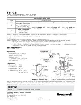

The 5817CB is a wireless transmitter that can be used with fire and burglary devices to send alarm signals to a control panel. It has three input loops - a primary supervised loop, a built-in reed switch loop, and a normally closed household burglary loop. DIP switches are used to configure the primary loop reporting and tamper switches protect the unit. The transmitter can be mounted using screws anchored to a wall stud.


