Download to read offline
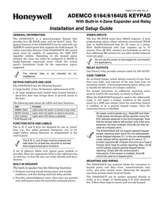

![1. Push the two case release snaps at the bottom of the Wiring Table
keypad with the blade of a medium screwdriver (this Keypad Control Panel Color
will push in the release snap), then pull that side of the LG Data Out Data In Green
case back away. Insert the screwdriver in the side of − GND − Aux Pwr Black
the keypad (between the front and back case) and + +12VDC + Aux Pwr Red
gently twist to release the side locking tab. Repeat for MY Data In Data Out Yellow
the other side. Refer to Figure 1 for location of the case
back release snaps and locking tabs. 5. Connect the wires for the four 2K EOLR zones to the
six screw terminals on keypad PC board as shown in
Figure 3 and as follows:
Keypad Wired Zone
ARMED
READY
CPU
Z1 + Zone 1
LOCKING
TAB
- Zone 1 and Zone 2 return
TO REMOVE REAR COVER
PUSH IN THE TWO MOUNTING
Z2 + Zone 2
SNAPS LOCATED ALONG THE
BOTTOM OF THE KEYPAD
AND LIFT COVER UP. Z3 + Zone 3
- Zone 3 and Zone 4 return
NOTE:
THE 6164US IS NOT MOUNTING Z4 + Zone 4
EQUIPPED WITH A RELEASE
CPU LED SNAPS 6164-003-V6 Note: There is a common ground for zones 1 and 2, and
one for zones 3 and 4.
Figure 1. Removing the Case Back
6. Connect the zone contact’s wires (door strike, etc.) to
2. Mount the case back to a wall or to an electrical box the three relay terminals marked NC, NO, and C as
using the 25mm-long self-tapping screws supplied shown in Figure 3 and as follows:
(anchors for drywall are not supplied).
Keypad Relay
If you wish to tamper-protect the keypad for
NO N.O. contact
removal from the wall, use an additional
mounting screw in the tamper hole in the case C Pole contact (common)
back (see Figure 2 for location). NC N.C. contact
3. Pass the four power/data wires, wires for up to four -
zones, and two or three relay contact wires through OPTIONAL
CONVENTIONAL
the opening in the case back. If surface wiring is being DOUBLE BALANCED EOLR
used, wiring may be routed through the top or the 2K 2K
bottom left-side breakout in the case back. See Figure TAMPER
[Y] DATA IN
2K
2. The breakouts must be punched out using a CONTACTS
N.O.
[+] +12VDC IN
screwdriver before mounting the case back. If desired,
wires may be strain-relieved to the wire tie point on 2K
TAMPER
CONTACTS
N.C. [-] GROUND (-12V)
the inside of the case back with a tie wrap (not
[G] DATA OUT
supplied).
BREAKOUT FOR
SURFACE WIRING N.O.
C.
N.C.
WIRE
TIE
POINT Y + G
Z1 Z4
Z2 Z3
USE AN
(Z1 (Z3
ADDITIONAL & &
MOUNTING Z2) Z4)
6164-005-V2
SCREW
HERE IF
BACK CASE
TAMPER IS
TO BE USED Figure 3. Wiring Details
7. Reattach the keypad to the mounted case back.
BREAKOUT
FOR Attach the top of the keypad first, and then press the
SURFACE bottom section down until it snaps into place
WIRING
MOUNTING securely.
HOLES 6164-02-V0
8. Peel off the protective film on the LED and keypad
Figure 2. Wiring Entry (Case Back) labels.
4. Connect the power/data wires to the four screw SETTING THE KEYPAD OPTIONS
terminals on the keypad’s PC board marked as shown The 6164/6164US allows eight items to be programmed
in Figure 3 and as follows: via local keypad programming mode:
-2-](https://image.slidesharecdn.com/honeywell-6164us-install-guide-120804184329-phpapp02/85/Honeywell-6164-us-install-guide-2-320.jpg)
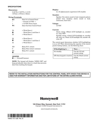
![• Keypad address • Tamper enable
• Zone expander enable • Display option
ZONE TYPE
• Zone expander address • Sound option EOLR [1=DBALAN]
DBALAN]
• Zone type • Language option
Either conventional EOL resistor supervised zones or
These settings are maintained even when keypad power is double-balanced zones (see Fig. 3) may be selected
removed. (default = conventional EOLR). Consult the panel’s
The keypad options may only be programmed within 60 installation guide for proper zone type selection. Use
seconds of applying power. After that, they are not the [✱] key to advance to the Tamper option.
accessible for editing or viewing. The Address can still be
viewed by holding down the 1 and 3 keys for approximately 6. By pressing the [1] key, you can toggle the Tamper
three (3) seconds. To re-enter programming mode, remove Enable option (default = OFF).
and reapply power and proceed as follows:
Perform the following steps to change the keypad options.
TAMPER
1. Enter the keypad's local program mode within 60 OFF [1 = ON]
seconds of power-up by pressing and holding down the Refer to the control panel’s installation guide to see if
[1] and [3] keys at the same time for 3 seconds. The the tamper feature is supported. Use the [✱] key to
current keypad address will be displayed with the advance to the LCD display option.
cursor under the "tens" digit.
7. By pressing either the [1], [2], or [3] keys you can
CON ADDRESS = 31 select the LCD display option.
DISPLAY
2. If the current keypad address setting is acceptable (the
default = 31), press the [✱] key to advance to the Zone
1=ON 2=KEY 3=DIS
Expander Enable field and go to step 3.
Option 1: The display is always active.
To change the current keypad address, first reset the
current address to “00” as follows: press [0] to clear the Option 2: The display and LEDs are blanked until a
“tens” digits. The cursor will move to the “ones” digit key is pressed, then displays for 45
position. Press [0] again to clear the “ones” digit. The seconds after the last key was pressed.
cursor will move back to the “tens” digit position. Now Option 3: The display and LEDs are blanked 45
set the desired keypad address as follows: seconds after the panel is armed and
Enter the proper “tens” digit for the keypad’s address. remains blanked until the panel is
The cursor will move to the “ones” digit. Enter the disarmed (default = 1).
proper “ones” digit for the keypad’s address. Press the Use the [✱] key to advance to the Sounds option.
[✱] key to store the displayed address and to advance 8. By pressing the [1] key, you can toggle the Sounds
to the Zone Expander Enable field. option (default = ALL SOUNDS).
3. By pressing the [1] key, you can toggle the Zone
Expander Enable option (default = OFF). SOUNDS
ZONE EXPANDER ALL [1=ALARM]
OFF [1 = ON] a. To produce all sounds set the option to ALL
SOUNDS.
a. To use zone contacts or relay, set the option to ON. b. To produce only key click and alarm sounds set the
Use the [✱] key to advance to the next option. The option to ALARM.
Zone Expander Address field will appear. Go to Use the [✱] key to advance to the Language option.
step 4.
b. To use the 6164/6164US as regular keypad, set the Use only English as the language for UL installations.
option to OFF. Use the [✱] key to advance to the
next option. The Tamper field will appear. Go to
9. For languages other than English enter [*]. For
step 6.
English language press [#]. This will also store the
4. Set the Expander zone address in the same way as the displayed settings and exit from the local programming
keypad address. mode.
EXP ADDRESS = 01 LANGUAGE?
* = YES # = NO
Consult the control panel’s installation guide to select the
Press [#] to advance to each of the listed languages.
correct address (default = 01). Use the [✱] key to advance
to the Zone Type option. Place the cursor placed to the left of the selected
language and press [✱] to continue with the selected
In order to use the built-in zones and relay, the panel language prompts.
must be programmed in the same way as for a 4229
module. DEU ENG ESP FR
5. By pressing the [1] key, you can toggle the Zone Type
option. IT NL RUS
-3-](https://image.slidesharecdn.com/honeywell-6164us-install-guide-120804184329-phpapp02/85/Honeywell-6164-us-install-guide-3-320.jpg)

The document provides installation and setup instructions for the ADEMCO 6164/6164US keypad with built-in 4-zone expander and relay. It includes details on the keypad's zones, relay outputs, displays, LEDs, wiring, mounting, and local programming options such as keypad address, zone type, and tamper enable settings.


