SlideShare a Scribd company logo
1 of 2
Download to read offline
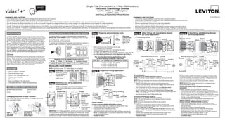
Single Pole (One location) or 3-Way (Multi-location)
Electronic Low Voltage Dimmer
Cat. No. VREØ6-1L, 600W (Lighted)
120VAC, 60Hz
INSTALLATION INSTRUCTIONS
DI-000-VRE06-02A
INSTALLING YOUR DIMMER
NOTE: Use check boxes when Steps are completed.√
Bk
RD
YL/RD
Coordinating Remote Dimmer
Wh
2
1 4
3
5
Black
Green
Red
Yellow/Red
1
3
2
White
4
5
Hot (Black)
Neutral (White)
DimmerCoordinating Remote (no LEDs)
YL/RD Yellow/RedRD
White
Red
Black
Black
BKWH
White
Green
Ground
Green
Ground
Electronic
Low Voltage
Transformer
Primary
Side
(unused)
(unused)
Line
120VAC
60Hz
Tools needed to install your Dimmer
Slotted/Phillips Screwdriver	 Electrical Tape	
Pliers				 Pencil		
Cutters			 Ruler
3-Way Wiring with Coordinating Remote
(no LEDs) Application:
Step 4b
Dimmer
Insulating
Label
BlackPrimary
Side
Electronic
Low Voltage
Transformer
hot (Black)Black
Line
120VAC, 60hz
Neutral (White)
Red
Yellow/Red
White
White
Green
Ground
Single-Pole Wiring Application:Step 4a
Black
Green
Red
Yellow/Red
Insulating Label:
This wire is used in
3-way installations only.
For single pole installations,
do not remove this
insulating label.
4
1
3
2
White
IMPORTANT: For 3-Way applications, note that one of the screw terminals
from the old switch being removed will usually be a different color (Black)
or labeled Common. Tag that wire with electrical tape and identify as the
common (Line or Load) in both the dimmer wall box and remote wall box.
Step 2 Identifying your wiring application
(most common):
NOTE: If the wiring in the wall box does not resemble
any of these configurations, consult a qualified
electrician.
2
4
3
1 2
4
1
5
3
3-Way
1.	 Line or Load
	 (See important 	
	 instruction 	
	 below)
2.	 Neutral
3.	 Ground
4.	 First Traveler 	
	 – note color
5.	 Second Traveler 	
	 – note color
Single-Pole
1.	 Line (Hot)
2.	 Neutral	
3.	 Ground
4.	 Load
INTRODUCTION
Leviton’s Vizia RF +TM
components are designed to communicate
with each other via Radio Frequency (RF) to provide remote control
of your lighting. Using RF technology allows Leviton to provide the
greatest signal integrity possible. Each module in Leviton’s Vizia
RF +TM
component line is a Z-Wave®
enabled device. In a Z-Wave®
network, each device is designed to act as a router. These routers
will re-transmit the RF signal from one device to another until the
intended device is reached. This ensures that the signal is received
by its intended device by routing the signal around obstacles and
radio dead spots. The Electronic Low Voltage Dimmer is compatible
with any Z-Wave®
enabled network, regardless of the manufacturer
and can also be used with other devices displaying the Z-Wave®
logo.
CAUTION:
Remember to exercise good common sense when using the Timer
features of your remote, especially when scheduling unattended
devices. There can be some unexpected consequences if not used
with care. For example, an empty coffee pot can be remotely turned
on. If that should happen, your coffee pot could be damaged from
overheating. If an electric heater is turned on by remote control
while clothing is draped over it, a fire could result.
•	 This is a Z-Wave®
controller
•	 Controls dimming of load
•	 ON/OFF LED and Brightness LED
•	 Two way communication
•	 RF reliability
•	 Ease of installation - No new wiring
•	 Compatible with other Z-Wave®
enabled devices
FEATURES
Changing the color of your Dimmer:
Your device may include color options. To change color of the
face, proceed as follows:
Line up tabs
and press in
sides one at a
time to attach
Push in
side at tab
to release
Installing Dimmer by itself or with other devices
If installing Dimmer in a single device application, proceed with the
Installing your Dimmer section. If installing Dimmer in a multi-
device application, proceed as follows:
Multi-device Application:
In multi-dimmer installations, the reduction of the dimmer’s capacity is
required. Refer to the chart for maximum load per dimmer.
MAXIMUM LOAD PER DIMMER FOR MULTI-DEVICE
Cat. No.
VREØ6 600W
Single
500W
Two Devices
400W
More than 2 Devices
Hot (Black)
Neutral (White)
DimmerMatching Remote (with LEDs)
YL/RD Red
Yellow/
Red
WH
BK Black
Black
White
Electronic
Low Voltage
Transformer
Green
GroundGreen
Ground
White
Primary
Side
Line
120VAC
60Hz
Additional
Neutral Wire
Bk
RD
YL/RD
Matching Remote
4
3
1
2
5
Dimmer
Wh
Black
Green
Red
Yellow/Red
3
2
White
4
5
1
Step 4c 3-Way Wiring with Matching Remote
(w/LEDs) Application:
Strip Gage
(measure bare
wire here or
use gage on
back of the
dimmer)
5/8”
(1.6 cm)
cut
(if necessary)
Step 3 Preparing and connecting wires:
•	 Make sure that the ends of the wires from the wall
box are straight (cut if necessary).
•	 Remove insulation from each wire in the wall box as shown.
•	 For Single Pole Application, go to Step 4a.
•	 For 3-Way Coordinating Remote (no LEDs) Application, go to Step 4b.
•	 For 3-Way Matching Remote (with LEDs) Application, go to Step 4c.
Step 1 WARNING: To avoid fire, shock, or death;	
turn off power
at circuit breaker or
fuse and test	
that power is off
before wiring!
Remove all
inner side
sections
Do not
remove
outer side
sections
WIRE NUT / # OF CONDUCTOR COMBINATION CHART
1- #12 w/ 1 to 3 #14, #16 or #18
2- #12 w/ 1 or 2 #16 or #18
1- #14 w/ 1 to 4 #16 or #18
2- #14 w/ 1 to 3 #16 or #18
For non-standard wiring applications, refer
to Wire Nut and Conductor Size Chart
WIRING DIMMER:
Connect wires per WIRING DIAGRAM as follows:
•	 Green or bare copper wire in wall box to Green dimmer lead.
•	 Line Hot wall box wire to Black dimmer lead.
•	 Load wall box wire to Red dimmer lead.
•	 Line Neutral wall box wire to White dimmer lead.
•	 Yellow/Red dimmer lead should have Red insulation label affixed.
	NOTE: If insulating label is not affixed to Yellow/Red dimmer lead,
use electrical tape to cover.
•	 Proceed to Step 5.
WARNINGS AND CAUTIONS:
•	 To be installed and/or used in accordance with appropriate electrical codes and regulations.
•	 If you are unsure about any part of these instructions, consult a qualified electrician.
•	 To avoid overheating and possible damage to this device and other equipment, do not install to control a receptacle, fluorescent lighting, a motor- or a transformer-operated appliance.
•	 Use with electronic low voltage transformers only. Do Not use to control a magnetic low voltage transformer. Use a Leviton magnetic low voltage dimmer to control magnetic low voltage transformers.
•	 This dimmer provides protection from overheating. An excessive load applied to the dimmer will cause the dimmer to overheat. The excess load must be removed to resume proper operation.
•	 Vizia RF +™ dimmers are not compatible with standard 3-way or 4-way switches. They must be used with compatible Vizia +™ remotes or Vizia RF +™ controllers for multi-location dimming.
•	 Use only one (1) Vizia RF +™ dimmer in a multi-location circuit with up to 9 coordinating remotes (without LEDs) or up to 4 matching remotes (with LEDs). The remote(s) will turn the light on at the brightness level selected at the dimmer.
•	 Lighting fixture and dimmer must be grounded.
WARNINGS AND CAUTIONS:
•	 This dimmer must be installed in a wall box with a neutral connection.
•	 Consult fixture manufacturer to determine if their solid state transformers can be dimmed.
•	 Total minimum load must exceed 40W.
•	 Dimmer may feel warm to the touch during normal operation.
•	 Recommended minimum wall box depth is 2-1/2.
•	 Maximum wire length from dimmer to all installed remotes cannot exceed 300 ft (90 m).
•	 Disconnect power at circuit breaker or fuse when servicing, installing or removing fixture.
•	 Use this device only with copper or copper clad wire. With aluminum wire use only devices marked CO/ALR or CU/AL.
WIRING DIMMER:
Connect wires per WIRING DIAGRAM as follows:
NOTE: The dimmer must be installed in a wall box that has a Line Hot
connection.
NOTE: Maximum wire length from dimmer to all installed remotes cannot
exceed 300 ft (90 m).
•	 Green or bare copper wire in wall box to Green dimmer lead.
•	 Line Hot (common) wall box wire identified (tagged) when removing old
switch to Black dimmer lead.
•	 First Traveler wall box wire to Red dimmer lead (note wire color).
•	 Remove Red insulating label from Yellow/Red dimmer lead.
•	 Second Traveler wall box wire to Yellow/Red dimmer lead (note wire
color). This traveler from the dimmer must go to the terminal screw on the
remote marked YL/RD.
•	 Line Neutral wall box wire to White dimmer lead.
WIRING coordinating remote:
Connect wires per WIRING DIAGRAM as follows:
NOTE: BK and RD terminals on coordinating remote are unused. 	
Tighten both screws.
NOTE: Maximum wire length from dimmer to last remote is
300 ft (90 m).
•	 Green or bare copper wire in wall box to Green terminal screw.
•	 Load wall box wire identified (tagged) when removing old switch to First
Traveler (note color as above).
•	 Second Traveler wall box wire (note color as above) to terminal screw
marked YL/RD. This traveler from the remote must go to the Yellow/Red
dimmer lead.
•	 Remove White insulating label from terminal screw marked WH.
•	 Line Neutral wall box wire to terminal screw marked WH.
•	 Proceed to Step 5.
NOTE: The dimmer must be installed in a wall box that has a Load
connection. The matching remote must be installed in a wall box with
a Line Hot connection and a Neutral connection. A Neutral wire to the
matching remote needs to be added as shown.
If you are unsure about any part of these instructions, consult a
qualified electrician.
NOTE: Maximum wire length from dimmer to all installed remotes
cannot exceed 300 ft (90 m).
Wiring Matching Remote (wall box with line hot
connection):
Connect wires per WIRING DIAGRAM as follows:
•	 Green or bare copper wire in wall box to Green terminal screw.
•	 Line Hot (common) wall box wire identified (tagged) when removing
old switch and First Traveler to Remote terminal marked BK.
•	 Second Traveler wall box wire from dimmer to remote terminal screw
marked YL/RD (note wire color). This traveler from the remote
must go to Yellow/Red dimmer lead.
•	 Line Neutral wall box to remote terminal screw marked WH.
Wiring Dimmer (wall box with load connection):
Connect wires per WIRING DIAGRAM as follows:
•	 Green or bare copper wire in wall box to Green dimmer lead.
•	 Load wall box wire identified (tagged) when removing old switch to
Red dimmer lead.
•	 First Traveler Line Hot to Black dimmer lead.
•	 Remove Red insulating label from Yellow/Red dimmer lead.
•	 Second Traveler wall box wire (note color as above) to
Yellow/Red dimmer lead. This traveler from the dimmer must go to
the terminal screw on the remote marked YL/RD.
•	 Line neutral wall box wire to White dimmer lead.
•	 Proceed to Step 5.
Including Scene Capable Dimmer into
Z-Wave®
Network:
Restore Power: Restore power at circuit breaker or	 	
fuse. Installation is complete.
D)	The Programmer/Controller will assign a node ID number (Name) for
this module.
	 NOTE: This ID number (Name) will be stored in the controller library
to be used for future reference.
	 NOTE: You may name or edit
your device at this time.
E)	The dimmer is now installed
in the network.
NOTE: If a dimmer has been
successfully Included in the
network and the user tries to
Include it again without first
excluding it from the network, the
module will retain the first node
ID it had received and ignore the
second.
Testing your Dimmer prior to mounting in	
	 wall box:
LIMITED 5 YEAR WARRANTY AND EXCLUSIONS
Leviton warrants to the original consumer purchaser and not for the benefit of anyone else that this product at the time of its sale by Leviton is free of defects in materials and workmanship under normal and proper use for five years from the purchase date. Leviton’s only obligation is to correct such defects by repair or replacement, at its option, if within such five year period the product is returned prepaid, with proof of
purchase date, and a description of the problem to Leviton Manufacturing Co., Inc., Att: Quality Assurance Department, 59-25 Little Neck Parkway, Little Neck, New York 11362-2591. This warranty excludes and there is disclaimed liability for labor for removal of this product or reinstallation. This warranty is void if this product is installed improperly or in an improper environment, overloaded, misused, opened,
abused, or altered in any manner, or is not used under normal operating conditions or not in accordance with any labels or instructions. There are no other or implied warranties of any kind, including merchantability and fitness for a particular purpose, but if any implied warranty is required by the applicable jurisdiction, the duration of any such implied warranty, including merchantability and fitness for a particular
purpose, is limited to five years. Leviton is not liable for incidental, indirect, special, or consequential damages, including without limitation, damage to, or loss of use of, any equipment, lost sales or profits or delay or failure to perform this warranty obligation. The remedies provided herein are the exclusive remedies under this warranty, whether based on contract, tort or otherwise.
•	 Restore power at circuit breaker or fuse.
•	 Press pad until locator light is OFF. Lights
should turn ON. If lights do not turn ON,
press the right half of DIM/BRIGHT bar until
the lights brighten.
	 If lights still do not turn ON, refer to the
TROUBLESHOOTING section.
NOTES:
•	 If using a non-Leviton Programmer/Controller,
refer to the Programmer/Controller instruction
sheet for Including a device.
•	 If using the VRCPG's Install Checklist feature,
go directly to Step B.
A)	If using a Leviton Z-Wave®
Programmer/
Controller, Cat. No. VRCPG, press the Menu
button and scroll down to System Setup.
Press the center button to select System
Setup Menu. Choose Advanced Settings.
Press the center button to select Network.
B)	While standing close to the module
(approx. 1 ft), press the center button to
Include device in the network.
	 NOTE: Only one device may be included at a time. DO NOT put
multiple devices into the Inclusion mode at any time.
C)	While the Programmer/Controller is in the Inclusion mode and the
Locator LED is ON on the dimmer, push the push pad to turn ON
the dimmer. The Programmer/Controller will verify inclusion and
the locator LED will turn OFF on the dimmer.
	 If the dimmer is flashing Amber while in the Inclusion mode, the
Programmer/Controller is still trying to communicate with the
dimmer. Wait until the device stops flashing,then press push pad.
	 NOTE: If the locator LED on the dimmer turns solid Red while
including, there has been a communication error. Refer to
Troubleshooting section. DI-000-VRE06-02A
Protected under U.S. Patent Number 6,388,399 and patents pending
and licensed under U.S. Patents Numbers 5,905,442, and 5,982,103
Programmer/Controller
Cat. No. VRCPG
Menu
Button
1 ON
2 ON
3 ON
4 ON
OFF
OFF
OFF
OFF
Center
Button
For additional information, contact Leviton’s Techline
at 1-800-824-3005 or visit Leviton’s website at
www.ViziaRFplus.com
NOTE: The locator light will illuminate when
the load is in the OFF position to facilitate
access in the dark.
NOTE: If using the dimmer in a 3-way
application, the lights will turn ON at
brightness set on dimmer’s DIM/BRIGHT bar.
The lighting can be controlled from either the
dimmer or the remote location.
Push Pad (Default settings)
Turn ON from OFF position:
Tap – Lights turn ON to preset level.
Press and Hold – Lights turn ON to full bright.
Turn OFF from ON position:
Tap – Lights turn OFF.
LED Brightness
Display
DIM/BRIGHT
Bar
Push
Pad
Locator
Light
OPERATION
Installation may now be completed
by tightening mounting screws into
wall box. Attach wallplate.
Dimmer Mounting:
Turn off power at
circuit breaker
or fuse.
Step 7
Step 6
NOTE: It is very important to accurately Exclude devices from the
network when moving or removing a device from a Z-Wave®
network.
This ensures that all information has been removed from your
Programmer/Controller’s information table and is not counted on to be a
part of the mesh network.
A)	If using a Leviton Z-Wave®
Programmer/Controller, Cat. No. VRCPG,
press the Menu button and scroll down to System Setup. Press
the center button to select System Setup Menu. Choose Advanced
Settings. Press the center button to select Network.
B)	While standing close to the dimmer, press the center button to
Exclude device from the network. While the Programmer/Controller
is in the Exclusion mode and the locator LED is ON on the dimmer,
press the push pad on the dimmer. The Programmer/Controller will
verify Exclusion and the locator LED will turn OFF on the dimmer.
	 If the dimmer is flashing Amber while in the Exlusion mode, the
Programmer/Controller is still trying to communicate with the dimmer.
Wait until the device stops flashing, then press the push pad.
Factory Default:
If your dimmer is not responding, or you are unable to control it after
you have tried to Include/Exclude it multiple times, it may be necessary
to reset the dimmer to its original factory settings. To accomplish this,
proceed as follows:
•	 On the dimmer, engage he air-gap switch (refer to Operation
section) and wait 5 seconds. Press push pad back into frame and
hold push pad until the locator LED turns Amber and then turns
Red. The dimmer is now reset. Once the dimmer is reset, it will be
necessary to Re-Include it to a network before it can be used.
CAUTION: SETTING A DEVICE TO A FACTORY DEFAULT DOES
NOT EXCLUDE THAT DEVICE FROM A NETWORK. THE EXCLUSION
PROCEDURE MUST STILL BE FOLLOWED TO REMOVE THE DEVICE
FROM THE PRIMARY CONTROLLER’S INFORMATION TABLE.
FAILURE TO DO SO MAY RESULT IN A SYSTEM THAT IS SLOW TO
RESPOND, OR MAY FAIL TO RESPOND TO SOME DEVICES.
Step 9 Excluding Dimmer from Network:
Step 8	
NOTE: Dress wires with a bend
as shown in diagram in order to
relieve stress when mounting
device.
•	 Position all wires to provide room in outlet 	
wall box for device.
•	 Ensure that the word “TOP” is facing up
on device strap.
•	 Partially screw in mounting screws in wall
box mounting holes.
Step 5
A-2)	 The Locator LED will blink 2 times per second to indicate the
device is in Program Mode A-2, Minimum Brightness Level.
To change the Minimum Brightness Level from 1-50%, use
the DIM/BRIGHT Bar. The light output will reflect the minimum
brightness level selected. By tapping the Push Pad this setting will
automatically be saved and the device will advance to the next
programming mode, A-3.
A-3)	 The Locator LED will blink 3 times per second to indicate Program
Mode A-3, Preset ON Level. To change the current Preset ON
Level from 1-100%, use the DIM/BRIGHT Bar. If this feature is
not desired, press and hold the left half of the DIM/BRIGHT Bar
(v) until no LED is lit (default setting). By tapping the Push Pad
this setting will automatically be saved and the device will exit
Programming Mode A.
Program Mode B
To enter Program Mode B:
Press and hold the Push Pad and then the left half of the
DIM/BRIGHT Bar (v) for 5 seconds until the Locator LED and rightmost
LED (LED 7) begin to blink.
B-1)	 Upon releasing the Push Pad and the left half of the
DIM/BRIGHT Bar (v), the Locator LED will continue to blink once
per second indicating he dimmer is in Program Mode B-1, ON
Fade Rate. To change the ON Fade Rate, use the DIM/BRIGHT
Bar to move the LED to the desired preset level according to Chart
B. By tapping the Push Pad this setting will automatically be saved
and the device will advance to the next programming mode, B-2.
B-2)	 The Locator LED will blink 2 times per second to indicate Program
Mode B-2, OFF Fade Rate. To change the OFF Fade Rate, use
the DIM/BRIGHT Bar to move the LED to the desired preset level
according to Chart B. By tapping the Push Pad this setting will
automatically be saved and the device will advance to the next
programming mode, B-3.
LED Brightness
Display
1 2 3 4 5 6 7
Definition of A Modes
A-1)	Energy Save: Sets the maximum brightness level for energy
savings.
A-2)	 Minimum Brightness Level: Sets the minimum dimming level.
A-3)	Preset ON Level: Sets the turn on brightness level regardless of
the previous set light level (formerly Dim Lock).
Definition of B Modes
B-1)	ON Fade Rate: Sets the amount of time in seconds it takes the
lights to turn ON to maximum brightness.
B-2)	OFF Fade Rate: Sets the amount of time in seconds it takes the
lights to turn OFF from maximum brightness.
B-3)	LED Options: Sets the time period in seconds the Locator LED
and Brightness display will stay on before extinguishing.
Definition of LEDs
Leftmost LED = LED 1
Rightmost LED = LED 7
NOTES:
•	 The device will exit programming
mode after 3 minutes of inactivity.
•	 Pressing the push pad at any time
during programming will advance the
device to the next programming mode.
ADVANCED PROGRAMMING FEATURES
Program Mode A
To enter Program Mode A:
Press and hold the Push Pad and then the right half of the
DIM/BRIGHT Bar (^) for 5 seconds until the Locator LED and
leftmost LED (LED 1) begin to blink.
A-1)	 Upon releasing the Push Pad and the right half of the
DIM/BRIGHT Bar (^), the Locator LED will continue to blink
once per second and the rightmost LED will illuminate to
display the device is in Program Mode A-1, Energy Save. The
default energy save mode is 100% i.e. full bright. To change
the Energy Save level, use the DIM/BRIGHT Bar to move
the corresponding LED to the desired discrete preset level
according to Chart A. By tapping the Push Pad this setting will
automatically be saved and the device will advance to the next
programming mode, A-2.
B-3)	 The Locator LED will blink 3 times per second to indicate Program
Mode B-3, LED Options. To change the LED Options settings,
use the DIM/BRIGHT Bar to move the LED to the desired preset
setting according to the Chart B-3. By tapping the Push Pad
this setting will automatically be saved and the device will exit
Programming Mode B.
LED
LED 1
LED 2 (Default)
LED 3
LED 4
LED 5
LED 6
LED 7
FADE ON
0 seconds (instant)
0.5 seconds
1.5 seconds
3.0 seconds
6.0 seconds
10 seconds
25 seconds
0 seconds (instant)
0.5 seconds
1.5 seconds
3.0 seconds
6.0 seconds
10 seconds
25 seconds
FADE OFF
Chart B
When indicator
light is at LED #
7
6
5
4
3
2
1
Light output is at
100%
97%
95%
90%
85%
80%
75%
Energy consumption
savings amounts to
0%
5%
8%
11%
14%
17%
20%
Chart A Chart B-3
LED
LED 1(default)
LED 2
LED 3
LED 4
LED 5
LED 6
LED 7
LOCATOR LED TIMEOUT
Active
Active
Active
Active
Turns off 5 sec. after use
LED BRIGHTNESS DISPLAY OPTIONS
Active
Turns off 5 sec. after use
Active
Turns off 5 sec. after use
LED Bar active
LED Bar turns off 5 sec. after use
VRCPG
Programmer/
Controller
NOTE: Remote must be in close
proximity to dimmer when including
in network.
DIM/BRIGHT Bar
BRIGHTEN:
Press right half of DIM/BRIGHT Bar – Lights brighten to desired level.
DIM:
Press left half of DIM/BRIGHT Bar – Lights dim to desired level.
If you continue to hold the left half of the DIM/BRIGHT Bar, the lights will
DIM to minimum level and then turn OFF.
NOTE: When lights are OFF you can change the
light level that the lights will turn ON to using the
DIM/BRIGHT Bar.
If there is a power outage, when the power is
restored the lights will return to the last setting
before the power interruption.
Air-Gap Switch: On the dimmer only, engage
the air-gap switch by gently pressing the
top of the push pad until the bottom lifts
completely out of the frame and a click is
heard (refer to Figure). LEDs will turn OFF.
This will cut power to the fixture to replace
the bulb. After servicing is complete, push the
push pad back for normal operation.
Cleaning: Clean with a damp cloth. DO NOT
use chemical cleaners.
Gently press top
of push pad
This equipment has been tested and found to comply with the limits
for a Class B Digital Device, pursuant to Part 15 of the FCC Rules.
These limits are designed to provide reasonable protection against
harmful interference in a residential installation. This equipment
generates, uses, and can radiate radio frequency energy and, if not
installed and used in accordance with the instructions, may cause
harmful interference to radio communications. However, there is no
guarantee that interference will not occur in a particular installation. If
this equipment does cause harmful interference to radio or television
reception, which can be determined by turning the equipment OFF
and ON, the user is encouraged to try to correct the interference by
one or more of the following measures:
•	 Reorient or relocate the receiving Antenna.
•	 Increase the separation between the equipment and the
receiver.
•	 Connect the equipment into an outlet on a circuit different from
that to which the receiver is connected.
•	 Consult the dealer or an experienced radio/tv technician for
help.
FCC COMPLIANCE STATEMENT
TROUBLESHOOTING
•	 	Lights Flickering
	 - 	Lamp has a bad connection.
- 	Wires not secured firmly with wire connectors of dimmer or 	
	 terminal screws of remote.
	 -	 Verify load type is electronic low voltage.
•	 Light does not turn ON and Locator LED does not turn ON
	 -	 Circuit breaker or fuse has tripped.
	 - 	Lamp is burned out.
	 - 	Neutral not wired to Dimmer (White wire).
•	 Intermittent dimmer operation
	 - 	Minimum load is under 40W.
•	 Remote does not operate lights
	 - 	Ensure that total wire length does not exceed 300 ft (90 m).
	 - 	Ensure wiring is correct.
•	 Lights cycle ON and OFF
	 - 	Remove excess load.
2008 © Leviton Mfg. Co., Inc.

More Related Content

What's hot

Edwards Signaling E-NAC Data Sheet
Edwards Signaling E-NAC Data SheetEdwards Signaling E-NAC Data Sheet
Edwards Signaling E-NAC Data SheetJMAC Supply
 
Manual Qubino smart meter plus
Manual Qubino smart meter plus Manual Qubino smart meter plus
Manual Qubino smart meter plus Domotica daVinci
 
Micro double switch module qubino manual
Micro double switch module qubino manualMicro double switch module qubino manual
Micro double switch module qubino manualDomotica daVinci
 
Benext BE_DIMMERPLUG_manual_us
Benext BE_DIMMERPLUG_manual_usBenext BE_DIMMERPLUG_manual_us
Benext BE_DIMMERPLUG_manual_usDomotica daVinci
 
Qubino weather station plus user manual v1.0_eng
Qubino weather station plus user manual v1.0_engQubino weather station plus user manual v1.0_eng
Qubino weather station plus user manual v1.0_engDomotica daVinci
 
Edwards Signaling E-NAC Installation Manual
Edwards Signaling E-NAC Installation ManualEdwards Signaling E-NAC Installation Manual
Edwards Signaling E-NAC Installation ManualJMAC Supply
 
In-wall dimmer module Z-Wave Plus Smart Home Europe manual english
In-wall dimmer module Z-Wave Plus Smart Home Europe manual englishIn-wall dimmer module Z-Wave Plus Smart Home Europe manual english
In-wall dimmer module Z-Wave Plus Smart Home Europe manual englishDomotica daVinci
 
PR Electronics 3000 Series High Performance Temperature Transmitters and Sign...
PR Electronics 3000 Series High Performance Temperature Transmitters and Sign...PR Electronics 3000 Series High Performance Temperature Transmitters and Sign...
PR Electronics 3000 Series High Performance Temperature Transmitters and Sign...Power Specialties, Inc.
 
PR Electronics 3000 Series High Performance Temperature Transmitters and Sign...
PR Electronics 3000 Series High Performance Temperature Transmitters and Sign...PR Electronics 3000 Series High Performance Temperature Transmitters and Sign...
PR Electronics 3000 Series High Performance Temperature Transmitters and Sign...Hile Controls of Alabama, Inc.
 
Micro switch module qubino manual
Micro switch module qubino manualMicro switch module qubino manual
Micro switch module qubino manualDomotica daVinci
 

What's hot (18)

Manual dimmer benext us
Manual dimmer benext usManual dimmer benext us
Manual dimmer benext us
 
Manual IKA232-20-230V
Manual IKA232-20-230VManual IKA232-20-230V
Manual IKA232-20-230V
 
Edwards Signaling E-NAC Data Sheet
Edwards Signaling E-NAC Data SheetEdwards Signaling E-NAC Data Sheet
Edwards Signaling E-NAC Data Sheet
 
Manual Qubino smart meter plus
Manual Qubino smart meter plus Manual Qubino smart meter plus
Manual Qubino smart meter plus
 
Micro double switch module qubino manual
Micro double switch module qubino manualMicro double switch module qubino manual
Micro double switch module qubino manual
 
Benext BE_DIMMERPLUG_manual_us
Benext BE_DIMMERPLUG_manual_usBenext BE_DIMMERPLUG_manual_us
Benext BE_DIMMERPLUG_manual_us
 
Qubino weather station plus user manual v1.0_eng
Qubino weather station plus user manual v1.0_engQubino weather station plus user manual v1.0_eng
Qubino weather station plus user manual v1.0_eng
 
I 9303
I 9303I 9303
I 9303
 
Edwards Signaling E-NAC Installation Manual
Edwards Signaling E-NAC Installation ManualEdwards Signaling E-NAC Installation Manual
Edwards Signaling E-NAC Installation Manual
 
In-wall dimmer module Z-Wave Plus Smart Home Europe manual english
In-wall dimmer module Z-Wave Plus Smart Home Europe manual englishIn-wall dimmer module Z-Wave Plus Smart Home Europe manual english
In-wall dimmer module Z-Wave Plus Smart Home Europe manual english
 
project
projectproject
project
 
S123 b30u
S123 b30uS123 b30u
S123 b30u
 
PR Electronics 3000 Series High Performance Temperature Transmitters and Sign...
PR Electronics 3000 Series High Performance Temperature Transmitters and Sign...PR Electronics 3000 Series High Performance Temperature Transmitters and Sign...
PR Electronics 3000 Series High Performance Temperature Transmitters and Sign...
 
PR Electronics 3000 Series High Performance Temperature Transmitters and Sign...
PR Electronics 3000 Series High Performance Temperature Transmitters and Sign...PR Electronics 3000 Series High Performance Temperature Transmitters and Sign...
PR Electronics 3000 Series High Performance Temperature Transmitters and Sign...
 
Mco_tps314
Mco_tps314Mco_tps314
Mco_tps314
 
Micro switch module qubino manual
Micro switch module qubino manualMicro switch module qubino manual
Micro switch module qubino manual
 
Scurve231 m en
Scurve231 m enScurve231 m en
Scurve231 m en
 
1232d
1232d1232d
1232d
 

Similar to Leviton vre06 1 lz

Leviton vri06 1 lz product manual and setup guide
Leviton vri06 1 lz product manual and setup guideLeviton vri06 1 lz product manual and setup guide
Leviton vri06 1 lz product manual and setup guideAlarm Grid
 
Leviton vrs15 1 lz installation manual and setup guide
Leviton vrs15 1 lz installation manual and setup guideLeviton vrs15 1 lz installation manual and setup guide
Leviton vrs15 1 lz installation manual and setup guideAlarm Grid
 
KL1034 Lect2 Electrical wiring.pdf
KL1034 Lect2 Electrical wiring.pdfKL1034 Lect2 Electrical wiring.pdf
KL1034 Lect2 Electrical wiring.pdfSysteDesig
 
Universal Dimmer 250W Z-Wave+ Fibaro Manual
Universal Dimmer 250W  Z-Wave+ Fibaro ManualUniversal Dimmer 250W  Z-Wave+ Fibaro Manual
Universal Dimmer 250W Z-Wave+ Fibaro ManualDomotica daVinci
 
Hướng dẫn sử dụng thiết bị kiểm tra dây cáp mạng TG - 20
 Hướng dẫn sử dụng thiết bị kiểm tra dây cáp mạng TG - 20 Hướng dẫn sử dụng thiết bị kiểm tra dây cáp mạng TG - 20
Hướng dẫn sử dụng thiết bị kiểm tra dây cáp mạng TG - 20Tenmars Việt Nam
 
Hướng dẫn sử dụng bộ kiểm tra mạng Extech 40180
Hướng dẫn sử dụng bộ kiểm tra mạng Extech 40180Hướng dẫn sử dụng bộ kiểm tra mạng Extech 40180
Hướng dẫn sử dụng bộ kiểm tra mạng Extech 40180Tenmars Việt Nam
 
Manual de la Mezcladora SoundCraft Notepad -12Fx
Manual de la Mezcladora SoundCraft Notepad -12FxManual de la Mezcladora SoundCraft Notepad -12Fx
Manual de la Mezcladora SoundCraft Notepad -12Fxjavierdavidvelasco17
 
Under Cabinet Lighting - UC2A Series from iLuXx - Installation Guide
Under Cabinet Lighting - UC2A Series from iLuXx - Installation GuideUnder Cabinet Lighting - UC2A Series from iLuXx - Installation Guide
Under Cabinet Lighting - UC2A Series from iLuXx - Installation Guideiluxx
 
Manual steinel rs led d2 (indoor light with led)
Manual steinel rs led d2 (indoor light with led)Manual steinel rs led d2 (indoor light with led)
Manual steinel rs led d2 (indoor light with led)Domotica daVinci
 
Components used in electrical installations
Components used in electrical installationsComponents used in electrical installations
Components used in electrical installationscatherinelindsay
 

Similar to Leviton vre06 1 lz (20)

Leviton vri06 1 lz product manual and setup guide
Leviton vri06 1 lz product manual and setup guideLeviton vri06 1 lz product manual and setup guide
Leviton vri06 1 lz product manual and setup guide
 
Leviton vrs15 1 lz installation manual and setup guide
Leviton vrs15 1 lz installation manual and setup guideLeviton vrs15 1 lz installation manual and setup guide
Leviton vrs15 1 lz installation manual and setup guide
 
Electrical safety
Electrical safetyElectrical safety
Electrical safety
 
KL1034 Lect2 Electrical wiring.pdf
KL1034 Lect2 Electrical wiring.pdfKL1034 Lect2 Electrical wiring.pdf
KL1034 Lect2 Electrical wiring.pdf
 
Universal Dimmer 250W Z-Wave+ Fibaro Manual
Universal Dimmer 250W  Z-Wave+ Fibaro ManualUniversal Dimmer 250W  Z-Wave+ Fibaro Manual
Universal Dimmer 250W Z-Wave+ Fibaro Manual
 
Electrical safety
Electrical safetyElectrical safety
Electrical safety
 
Hướng dẫn sử dụng thiết bị kiểm tra dây cáp mạng TG - 20
 Hướng dẫn sử dụng thiết bị kiểm tra dây cáp mạng TG - 20 Hướng dẫn sử dụng thiết bị kiểm tra dây cáp mạng TG - 20
Hướng dẫn sử dụng thiết bị kiểm tra dây cáp mạng TG - 20
 
Hướng dẫn sử dụng bộ kiểm tra mạng Extech 40180
Hướng dẫn sử dụng bộ kiểm tra mạng Extech 40180Hướng dẫn sử dụng bộ kiểm tra mạng Extech 40180
Hướng dẫn sử dụng bộ kiểm tra mạng Extech 40180
 
Vfd l m-en_20030522
Vfd l m-en_20030522Vfd l m-en_20030522
Vfd l m-en_20030522
 
Manual de la Mezcladora SoundCraft Notepad -12Fx
Manual de la Mezcladora SoundCraft Notepad -12FxManual de la Mezcladora SoundCraft Notepad -12Fx
Manual de la Mezcladora SoundCraft Notepad -12Fx
 
Aw16 ge
Aw16 geAw16 ge
Aw16 ge
 
Under Cabinet Lighting - UC2A Series from iLuXx - Installation Guide
Under Cabinet Lighting - UC2A Series from iLuXx - Installation GuideUnder Cabinet Lighting - UC2A Series from iLuXx - Installation Guide
Under Cabinet Lighting - UC2A Series from iLuXx - Installation Guide
 
Vibrating Rod Point Level Switch for Solids India
Vibrating Rod Point Level Switch for Solids IndiaVibrating Rod Point Level Switch for Solids India
Vibrating Rod Point Level Switch for Solids India
 
Vibrating Rod Level Switch for Solids.pdf
Vibrating Rod Level Switch for Solids.pdfVibrating Rod Level Switch for Solids.pdf
Vibrating Rod Level Switch for Solids.pdf
 
Residential wiring PPT.pptx
Residential wiring PPT.pptxResidential wiring PPT.pptx
Residential wiring PPT.pptx
 
Manual steinel rs led d2 (indoor light with led)
Manual steinel rs led d2 (indoor light with led)Manual steinel rs led d2 (indoor light with led)
Manual steinel rs led d2 (indoor light with led)
 
P Series PowerPlex™ Distribution Panelboards
P Series PowerPlex™ Distribution PanelboardsP Series PowerPlex™ Distribution Panelboards
P Series PowerPlex™ Distribution Panelboards
 
Components used in electrical installations
Components used in electrical installationsComponents used in electrical installations
Components used in electrical installations
 
Ex rc1 spec-en_1215
Ex rc1 spec-en_1215Ex rc1 spec-en_1215
Ex rc1 spec-en_1215
 
Vibrating Fork Level Limit Switch for Solids.pdf
Vibrating Fork Level Limit Switch for Solids.pdfVibrating Fork Level Limit Switch for Solids.pdf
Vibrating Fork Level Limit Switch for Solids.pdf
 

More from Alarm Grid

Vizia rf + system programming and control
Vizia rf + system programming and controlVizia rf + system programming and control
Vizia rf + system programming and controlAlarm Grid
 
Vizia rf + plug in spec sheet
Vizia rf + plug in spec sheetVizia rf + plug in spec sheet
Vizia rf + plug in spec sheetAlarm Grid
 
Leviton vrs05 1 lz installation manual and setup guide
Leviton vrs05 1 lz installation manual and setup guideLeviton vrs05 1 lz installation manual and setup guide
Leviton vrs05 1 lz installation manual and setup guideAlarm Grid
 
Leviton vrr15 1 lz product specification bulletin
Leviton vrr15 1 lz product specification bulletinLeviton vrr15 1 lz product specification bulletin
Leviton vrr15 1 lz product specification bulletinAlarm Grid
 
Leviton vrp15 z Installation Instructions and Setup Guide
Leviton vrp15 z Installation Instructions and Setup GuideLeviton vrp15 z Installation Instructions and Setup Guide
Leviton vrp15 z Installation Instructions and Setup GuideAlarm Grid
 
Leviton vrp03 z product manual and setup guide
Leviton vrp03 z product manual and setup guideLeviton vrp03 z product manual and setup guide
Leviton vrp03 z product manual and setup guideAlarm Grid
 
Leviton vrf01 1 lz product manual and setup guide
Leviton vrf01 1 lz product manual and setup guideLeviton vrf01 1 lz product manual and setup guide
Leviton vrf01 1 lz product manual and setup guideAlarm Grid
 
Leviton vrcz4 mr, vrcs4-mr, and vrc52-mr product specifications
Leviton vrcz4 mr, vrcs4-mr, and vrc52-mr product specificationsLeviton vrcz4 mr, vrcs4-mr, and vrc52-mr product specifications
Leviton vrcz4 mr, vrcs4-mr, and vrc52-mr product specificationsAlarm Grid
 
Leviton vrcz4 1 l, vrcs4-1l, vrcz1-1l, vrcs1-1l and vrmr1-osg product specifi...
Leviton vrcz4 1 l, vrcs4-1l, vrcz1-1l, vrcs1-1l and vrmr1-osg product specifi...Leviton vrcz4 1 l, vrcs4-1l, vrcz1-1l, vrcs1-1l and vrmr1-osg product specifi...
Leviton vrcz4 1 l, vrcs4-1l, vrcz1-1l, vrcs1-1l and vrmr1-osg product specifi...Alarm Grid
 
Leviton vrcz1 installation manual and setup guide
Leviton vrcz1 installation manual and setup guideLeviton vrcz1 installation manual and setup guide
Leviton vrcz1 installation manual and setup guideAlarm Grid
 
Leviton vrcs1 1 l
Leviton vrcs1 1 lLeviton vrcs1 1 l
Leviton vrcs1 1 lAlarm Grid
 
Leviton vp00 r 10z, vp00r-1lz, vp0sr-10z, vp0sr-1lz installation manual and s...
Leviton vp00 r 10z, vp00r-1lz, vp0sr-10z, vp0sr-1lz installation manual and s...Leviton vp00 r 10z, vp00r-1lz, vp0sr-10z, vp0sr-1lz installation manual and s...
Leviton vp00 r 10z, vp00r-1lz, vp0sr-10z, vp0sr-1lz installation manual and s...Alarm Grid
 
Leviton dimmers, switches and fan speed controllers
Leviton dimmers, switches and fan speed controllersLeviton dimmers, switches and fan speed controllers
Leviton dimmers, switches and fan speed controllersAlarm Grid
 
Fluorescent dimmer for hi lume or eco-10 ballasts
Fluorescent dimmer for hi lume or eco-10 ballastsFluorescent dimmer for hi lume or eco-10 ballasts
Fluorescent dimmer for hi lume or eco-10 ballastsAlarm Grid
 
Controlling z wave door locks with the vrc0 p
Controlling z wave door locks with the vrc0 pControlling z wave door locks with the vrc0 p
Controlling z wave door locks with the vrc0 pAlarm Grid
 
Vizia rf+ collection
Vizia rf+ collectionVizia rf+ collection
Vizia rf+ collectionAlarm Grid
 
Honeywell vista-50p-user-guide
Honeywell vista-50p-user-guideHoneywell vista-50p-user-guide
Honeywell vista-50p-user-guideAlarm Grid
 
Honeywell vista-50p-install-guide
Honeywell vista-50p-install-guideHoneywell vista-50p-install-guide
Honeywell vista-50p-install-guideAlarm Grid
 
Honeywell vista-50p-connections-summary
Honeywell vista-50p-connections-summaryHoneywell vista-50p-connections-summary
Honeywell vista-50p-connections-summaryAlarm Grid
 
Honeywell vista-10p-programming-guide
Honeywell vista-10p-programming-guideHoneywell vista-10p-programming-guide
Honeywell vista-10p-programming-guideAlarm Grid
 

More from Alarm Grid (20)

Vizia rf + system programming and control
Vizia rf + system programming and controlVizia rf + system programming and control
Vizia rf + system programming and control
 
Vizia rf + plug in spec sheet
Vizia rf + plug in spec sheetVizia rf + plug in spec sheet
Vizia rf + plug in spec sheet
 
Leviton vrs05 1 lz installation manual and setup guide
Leviton vrs05 1 lz installation manual and setup guideLeviton vrs05 1 lz installation manual and setup guide
Leviton vrs05 1 lz installation manual and setup guide
 
Leviton vrr15 1 lz product specification bulletin
Leviton vrr15 1 lz product specification bulletinLeviton vrr15 1 lz product specification bulletin
Leviton vrr15 1 lz product specification bulletin
 
Leviton vrp15 z Installation Instructions and Setup Guide
Leviton vrp15 z Installation Instructions and Setup GuideLeviton vrp15 z Installation Instructions and Setup Guide
Leviton vrp15 z Installation Instructions and Setup Guide
 
Leviton vrp03 z product manual and setup guide
Leviton vrp03 z product manual and setup guideLeviton vrp03 z product manual and setup guide
Leviton vrp03 z product manual and setup guide
 
Leviton vrf01 1 lz product manual and setup guide
Leviton vrf01 1 lz product manual and setup guideLeviton vrf01 1 lz product manual and setup guide
Leviton vrf01 1 lz product manual and setup guide
 
Leviton vrcz4 mr, vrcs4-mr, and vrc52-mr product specifications
Leviton vrcz4 mr, vrcs4-mr, and vrc52-mr product specificationsLeviton vrcz4 mr, vrcs4-mr, and vrc52-mr product specifications
Leviton vrcz4 mr, vrcs4-mr, and vrc52-mr product specifications
 
Leviton vrcz4 1 l, vrcs4-1l, vrcz1-1l, vrcs1-1l and vrmr1-osg product specifi...
Leviton vrcz4 1 l, vrcs4-1l, vrcz1-1l, vrcs1-1l and vrmr1-osg product specifi...Leviton vrcz4 1 l, vrcs4-1l, vrcz1-1l, vrcs1-1l and vrmr1-osg product specifi...
Leviton vrcz4 1 l, vrcs4-1l, vrcz1-1l, vrcs1-1l and vrmr1-osg product specifi...
 
Leviton vrcz1 installation manual and setup guide
Leviton vrcz1 installation manual and setup guideLeviton vrcz1 installation manual and setup guide
Leviton vrcz1 installation manual and setup guide
 
Leviton vrcs1 1 l
Leviton vrcs1 1 lLeviton vrcs1 1 l
Leviton vrcs1 1 l
 
Leviton vp00 r 10z, vp00r-1lz, vp0sr-10z, vp0sr-1lz installation manual and s...
Leviton vp00 r 10z, vp00r-1lz, vp0sr-10z, vp0sr-1lz installation manual and s...Leviton vp00 r 10z, vp00r-1lz, vp0sr-10z, vp0sr-1lz installation manual and s...
Leviton vp00 r 10z, vp00r-1lz, vp0sr-10z, vp0sr-1lz installation manual and s...
 
Leviton dimmers, switches and fan speed controllers
Leviton dimmers, switches and fan speed controllersLeviton dimmers, switches and fan speed controllers
Leviton dimmers, switches and fan speed controllers
 
Fluorescent dimmer for hi lume or eco-10 ballasts
Fluorescent dimmer for hi lume or eco-10 ballastsFluorescent dimmer for hi lume or eco-10 ballasts
Fluorescent dimmer for hi lume or eco-10 ballasts
 
Controlling z wave door locks with the vrc0 p
Controlling z wave door locks with the vrc0 pControlling z wave door locks with the vrc0 p
Controlling z wave door locks with the vrc0 p
 
Vizia rf+ collection
Vizia rf+ collectionVizia rf+ collection
Vizia rf+ collection
 
Honeywell vista-50p-user-guide
Honeywell vista-50p-user-guideHoneywell vista-50p-user-guide
Honeywell vista-50p-user-guide
 
Honeywell vista-50p-install-guide
Honeywell vista-50p-install-guideHoneywell vista-50p-install-guide
Honeywell vista-50p-install-guide
 
Honeywell vista-50p-connections-summary
Honeywell vista-50p-connections-summaryHoneywell vista-50p-connections-summary
Honeywell vista-50p-connections-summary
 
Honeywell vista-10p-programming-guide
Honeywell vista-10p-programming-guideHoneywell vista-10p-programming-guide
Honeywell vista-10p-programming-guide
 

Leviton vre06 1 lz

  • 1. Single Pole (One location) or 3-Way (Multi-location) Electronic Low Voltage Dimmer Cat. No. VREØ6-1L, 600W (Lighted) 120VAC, 60Hz INSTALLATION INSTRUCTIONS DI-000-VRE06-02A INSTALLING YOUR DIMMER NOTE: Use check boxes when Steps are completed.√ Bk RD YL/RD Coordinating Remote Dimmer Wh 2 1 4 3 5 Black Green Red Yellow/Red 1 3 2 White 4 5 Hot (Black) Neutral (White) DimmerCoordinating Remote (no LEDs) YL/RD Yellow/RedRD White Red Black Black BKWH White Green Ground Green Ground Electronic Low Voltage Transformer Primary Side (unused) (unused) Line 120VAC 60Hz Tools needed to install your Dimmer Slotted/Phillips Screwdriver Electrical Tape Pliers Pencil Cutters Ruler 3-Way Wiring with Coordinating Remote (no LEDs) Application: Step 4b Dimmer Insulating Label BlackPrimary Side Electronic Low Voltage Transformer hot (Black)Black Line 120VAC, 60hz Neutral (White) Red Yellow/Red White White Green Ground Single-Pole Wiring Application:Step 4a Black Green Red Yellow/Red Insulating Label: This wire is used in 3-way installations only. For single pole installations, do not remove this insulating label. 4 1 3 2 White IMPORTANT: For 3-Way applications, note that one of the screw terminals from the old switch being removed will usually be a different color (Black) or labeled Common. Tag that wire with electrical tape and identify as the common (Line or Load) in both the dimmer wall box and remote wall box. Step 2 Identifying your wiring application (most common): NOTE: If the wiring in the wall box does not resemble any of these configurations, consult a qualified electrician. 2 4 3 1 2 4 1 5 3 3-Way 1. Line or Load (See important instruction below) 2. Neutral 3. Ground 4. First Traveler – note color 5. Second Traveler – note color Single-Pole 1. Line (Hot) 2. Neutral 3. Ground 4. Load INTRODUCTION Leviton’s Vizia RF +TM components are designed to communicate with each other via Radio Frequency (RF) to provide remote control of your lighting. Using RF technology allows Leviton to provide the greatest signal integrity possible. Each module in Leviton’s Vizia RF +TM component line is a Z-Wave® enabled device. In a Z-Wave® network, each device is designed to act as a router. These routers will re-transmit the RF signal from one device to another until the intended device is reached. This ensures that the signal is received by its intended device by routing the signal around obstacles and radio dead spots. The Electronic Low Voltage Dimmer is compatible with any Z-Wave® enabled network, regardless of the manufacturer and can also be used with other devices displaying the Z-Wave® logo. CAUTION: Remember to exercise good common sense when using the Timer features of your remote, especially when scheduling unattended devices. There can be some unexpected consequences if not used with care. For example, an empty coffee pot can be remotely turned on. If that should happen, your coffee pot could be damaged from overheating. If an electric heater is turned on by remote control while clothing is draped over it, a fire could result. • This is a Z-Wave® controller • Controls dimming of load • ON/OFF LED and Brightness LED • Two way communication • RF reliability • Ease of installation - No new wiring • Compatible with other Z-Wave® enabled devices FEATURES Changing the color of your Dimmer: Your device may include color options. To change color of the face, proceed as follows: Line up tabs and press in sides one at a time to attach Push in side at tab to release Installing Dimmer by itself or with other devices If installing Dimmer in a single device application, proceed with the Installing your Dimmer section. If installing Dimmer in a multi- device application, proceed as follows: Multi-device Application: In multi-dimmer installations, the reduction of the dimmer’s capacity is required. Refer to the chart for maximum load per dimmer. MAXIMUM LOAD PER DIMMER FOR MULTI-DEVICE Cat. No. VREØ6 600W Single 500W Two Devices 400W More than 2 Devices Hot (Black) Neutral (White) DimmerMatching Remote (with LEDs) YL/RD Red Yellow/ Red WH BK Black Black White Electronic Low Voltage Transformer Green GroundGreen Ground White Primary Side Line 120VAC 60Hz Additional Neutral Wire Bk RD YL/RD Matching Remote 4 3 1 2 5 Dimmer Wh Black Green Red Yellow/Red 3 2 White 4 5 1 Step 4c 3-Way Wiring with Matching Remote (w/LEDs) Application: Strip Gage (measure bare wire here or use gage on back of the dimmer) 5/8” (1.6 cm) cut (if necessary) Step 3 Preparing and connecting wires: • Make sure that the ends of the wires from the wall box are straight (cut if necessary). • Remove insulation from each wire in the wall box as shown. • For Single Pole Application, go to Step 4a. • For 3-Way Coordinating Remote (no LEDs) Application, go to Step 4b. • For 3-Way Matching Remote (with LEDs) Application, go to Step 4c. Step 1 WARNING: To avoid fire, shock, or death; turn off power at circuit breaker or fuse and test that power is off before wiring! Remove all inner side sections Do not remove outer side sections WIRE NUT / # OF CONDUCTOR COMBINATION CHART 1- #12 w/ 1 to 3 #14, #16 or #18 2- #12 w/ 1 or 2 #16 or #18 1- #14 w/ 1 to 4 #16 or #18 2- #14 w/ 1 to 3 #16 or #18 For non-standard wiring applications, refer to Wire Nut and Conductor Size Chart WIRING DIMMER: Connect wires per WIRING DIAGRAM as follows: • Green or bare copper wire in wall box to Green dimmer lead. • Line Hot wall box wire to Black dimmer lead. • Load wall box wire to Red dimmer lead. • Line Neutral wall box wire to White dimmer lead. • Yellow/Red dimmer lead should have Red insulation label affixed. NOTE: If insulating label is not affixed to Yellow/Red dimmer lead, use electrical tape to cover. • Proceed to Step 5. WARNINGS AND CAUTIONS: • To be installed and/or used in accordance with appropriate electrical codes and regulations. • If you are unsure about any part of these instructions, consult a qualified electrician. • To avoid overheating and possible damage to this device and other equipment, do not install to control a receptacle, fluorescent lighting, a motor- or a transformer-operated appliance. • Use with electronic low voltage transformers only. Do Not use to control a magnetic low voltage transformer. Use a Leviton magnetic low voltage dimmer to control magnetic low voltage transformers. • This dimmer provides protection from overheating. An excessive load applied to the dimmer will cause the dimmer to overheat. The excess load must be removed to resume proper operation. • Vizia RF +™ dimmers are not compatible with standard 3-way or 4-way switches. They must be used with compatible Vizia +™ remotes or Vizia RF +™ controllers for multi-location dimming. • Use only one (1) Vizia RF +™ dimmer in a multi-location circuit with up to 9 coordinating remotes (without LEDs) or up to 4 matching remotes (with LEDs). The remote(s) will turn the light on at the brightness level selected at the dimmer. • Lighting fixture and dimmer must be grounded. WARNINGS AND CAUTIONS: • This dimmer must be installed in a wall box with a neutral connection. • Consult fixture manufacturer to determine if their solid state transformers can be dimmed. • Total minimum load must exceed 40W. • Dimmer may feel warm to the touch during normal operation. • Recommended minimum wall box depth is 2-1/2. • Maximum wire length from dimmer to all installed remotes cannot exceed 300 ft (90 m). • Disconnect power at circuit breaker or fuse when servicing, installing or removing fixture. • Use this device only with copper or copper clad wire. With aluminum wire use only devices marked CO/ALR or CU/AL. WIRING DIMMER: Connect wires per WIRING DIAGRAM as follows: NOTE: The dimmer must be installed in a wall box that has a Line Hot connection. NOTE: Maximum wire length from dimmer to all installed remotes cannot exceed 300 ft (90 m). • Green or bare copper wire in wall box to Green dimmer lead. • Line Hot (common) wall box wire identified (tagged) when removing old switch to Black dimmer lead. • First Traveler wall box wire to Red dimmer lead (note wire color). • Remove Red insulating label from Yellow/Red dimmer lead. • Second Traveler wall box wire to Yellow/Red dimmer lead (note wire color). This traveler from the dimmer must go to the terminal screw on the remote marked YL/RD. • Line Neutral wall box wire to White dimmer lead. WIRING coordinating remote: Connect wires per WIRING DIAGRAM as follows: NOTE: BK and RD terminals on coordinating remote are unused. Tighten both screws. NOTE: Maximum wire length from dimmer to last remote is 300 ft (90 m). • Green or bare copper wire in wall box to Green terminal screw. • Load wall box wire identified (tagged) when removing old switch to First Traveler (note color as above). • Second Traveler wall box wire (note color as above) to terminal screw marked YL/RD. This traveler from the remote must go to the Yellow/Red dimmer lead. • Remove White insulating label from terminal screw marked WH. • Line Neutral wall box wire to terminal screw marked WH. • Proceed to Step 5. NOTE: The dimmer must be installed in a wall box that has a Load connection. The matching remote must be installed in a wall box with a Line Hot connection and a Neutral connection. A Neutral wire to the matching remote needs to be added as shown. If you are unsure about any part of these instructions, consult a qualified electrician. NOTE: Maximum wire length from dimmer to all installed remotes cannot exceed 300 ft (90 m). Wiring Matching Remote (wall box with line hot connection): Connect wires per WIRING DIAGRAM as follows: • Green or bare copper wire in wall box to Green terminal screw. • Line Hot (common) wall box wire identified (tagged) when removing old switch and First Traveler to Remote terminal marked BK. • Second Traveler wall box wire from dimmer to remote terminal screw marked YL/RD (note wire color). This traveler from the remote must go to Yellow/Red dimmer lead. • Line Neutral wall box to remote terminal screw marked WH. Wiring Dimmer (wall box with load connection): Connect wires per WIRING DIAGRAM as follows: • Green or bare copper wire in wall box to Green dimmer lead. • Load wall box wire identified (tagged) when removing old switch to Red dimmer lead. • First Traveler Line Hot to Black dimmer lead. • Remove Red insulating label from Yellow/Red dimmer lead. • Second Traveler wall box wire (note color as above) to Yellow/Red dimmer lead. This traveler from the dimmer must go to the terminal screw on the remote marked YL/RD. • Line neutral wall box wire to White dimmer lead. • Proceed to Step 5.
  • 2. Including Scene Capable Dimmer into Z-Wave® Network: Restore Power: Restore power at circuit breaker or fuse. Installation is complete. D) The Programmer/Controller will assign a node ID number (Name) for this module. NOTE: This ID number (Name) will be stored in the controller library to be used for future reference. NOTE: You may name or edit your device at this time. E) The dimmer is now installed in the network. NOTE: If a dimmer has been successfully Included in the network and the user tries to Include it again without first excluding it from the network, the module will retain the first node ID it had received and ignore the second. Testing your Dimmer prior to mounting in wall box: LIMITED 5 YEAR WARRANTY AND EXCLUSIONS Leviton warrants to the original consumer purchaser and not for the benefit of anyone else that this product at the time of its sale by Leviton is free of defects in materials and workmanship under normal and proper use for five years from the purchase date. Leviton’s only obligation is to correct such defects by repair or replacement, at its option, if within such five year period the product is returned prepaid, with proof of purchase date, and a description of the problem to Leviton Manufacturing Co., Inc., Att: Quality Assurance Department, 59-25 Little Neck Parkway, Little Neck, New York 11362-2591. This warranty excludes and there is disclaimed liability for labor for removal of this product or reinstallation. This warranty is void if this product is installed improperly or in an improper environment, overloaded, misused, opened, abused, or altered in any manner, or is not used under normal operating conditions or not in accordance with any labels or instructions. There are no other or implied warranties of any kind, including merchantability and fitness for a particular purpose, but if any implied warranty is required by the applicable jurisdiction, the duration of any such implied warranty, including merchantability and fitness for a particular purpose, is limited to five years. Leviton is not liable for incidental, indirect, special, or consequential damages, including without limitation, damage to, or loss of use of, any equipment, lost sales or profits or delay or failure to perform this warranty obligation. The remedies provided herein are the exclusive remedies under this warranty, whether based on contract, tort or otherwise. • Restore power at circuit breaker or fuse. • Press pad until locator light is OFF. Lights should turn ON. If lights do not turn ON, press the right half of DIM/BRIGHT bar until the lights brighten. If lights still do not turn ON, refer to the TROUBLESHOOTING section. NOTES: • If using a non-Leviton Programmer/Controller, refer to the Programmer/Controller instruction sheet for Including a device. • If using the VRCPG's Install Checklist feature, go directly to Step B. A) If using a Leviton Z-Wave® Programmer/ Controller, Cat. No. VRCPG, press the Menu button and scroll down to System Setup. Press the center button to select System Setup Menu. Choose Advanced Settings. Press the center button to select Network. B) While standing close to the module (approx. 1 ft), press the center button to Include device in the network. NOTE: Only one device may be included at a time. DO NOT put multiple devices into the Inclusion mode at any time. C) While the Programmer/Controller is in the Inclusion mode and the Locator LED is ON on the dimmer, push the push pad to turn ON the dimmer. The Programmer/Controller will verify inclusion and the locator LED will turn OFF on the dimmer. If the dimmer is flashing Amber while in the Inclusion mode, the Programmer/Controller is still trying to communicate with the dimmer. Wait until the device stops flashing,then press push pad. NOTE: If the locator LED on the dimmer turns solid Red while including, there has been a communication error. Refer to Troubleshooting section. DI-000-VRE06-02A Protected under U.S. Patent Number 6,388,399 and patents pending and licensed under U.S. Patents Numbers 5,905,442, and 5,982,103 Programmer/Controller Cat. No. VRCPG Menu Button 1 ON 2 ON 3 ON 4 ON OFF OFF OFF OFF Center Button For additional information, contact Leviton’s Techline at 1-800-824-3005 or visit Leviton’s website at www.ViziaRFplus.com NOTE: The locator light will illuminate when the load is in the OFF position to facilitate access in the dark. NOTE: If using the dimmer in a 3-way application, the lights will turn ON at brightness set on dimmer’s DIM/BRIGHT bar. The lighting can be controlled from either the dimmer or the remote location. Push Pad (Default settings) Turn ON from OFF position: Tap – Lights turn ON to preset level. Press and Hold – Lights turn ON to full bright. Turn OFF from ON position: Tap – Lights turn OFF. LED Brightness Display DIM/BRIGHT Bar Push Pad Locator Light OPERATION Installation may now be completed by tightening mounting screws into wall box. Attach wallplate. Dimmer Mounting: Turn off power at circuit breaker or fuse. Step 7 Step 6 NOTE: It is very important to accurately Exclude devices from the network when moving or removing a device from a Z-Wave® network. This ensures that all information has been removed from your Programmer/Controller’s information table and is not counted on to be a part of the mesh network. A) If using a Leviton Z-Wave® Programmer/Controller, Cat. No. VRCPG, press the Menu button and scroll down to System Setup. Press the center button to select System Setup Menu. Choose Advanced Settings. Press the center button to select Network. B) While standing close to the dimmer, press the center button to Exclude device from the network. While the Programmer/Controller is in the Exclusion mode and the locator LED is ON on the dimmer, press the push pad on the dimmer. The Programmer/Controller will verify Exclusion and the locator LED will turn OFF on the dimmer. If the dimmer is flashing Amber while in the Exlusion mode, the Programmer/Controller is still trying to communicate with the dimmer. Wait until the device stops flashing, then press the push pad. Factory Default: If your dimmer is not responding, or you are unable to control it after you have tried to Include/Exclude it multiple times, it may be necessary to reset the dimmer to its original factory settings. To accomplish this, proceed as follows: • On the dimmer, engage he air-gap switch (refer to Operation section) and wait 5 seconds. Press push pad back into frame and hold push pad until the locator LED turns Amber and then turns Red. The dimmer is now reset. Once the dimmer is reset, it will be necessary to Re-Include it to a network before it can be used. CAUTION: SETTING A DEVICE TO A FACTORY DEFAULT DOES NOT EXCLUDE THAT DEVICE FROM A NETWORK. THE EXCLUSION PROCEDURE MUST STILL BE FOLLOWED TO REMOVE THE DEVICE FROM THE PRIMARY CONTROLLER’S INFORMATION TABLE. FAILURE TO DO SO MAY RESULT IN A SYSTEM THAT IS SLOW TO RESPOND, OR MAY FAIL TO RESPOND TO SOME DEVICES. Step 9 Excluding Dimmer from Network: Step 8 NOTE: Dress wires with a bend as shown in diagram in order to relieve stress when mounting device. • Position all wires to provide room in outlet wall box for device. • Ensure that the word “TOP” is facing up on device strap. • Partially screw in mounting screws in wall box mounting holes. Step 5 A-2) The Locator LED will blink 2 times per second to indicate the device is in Program Mode A-2, Minimum Brightness Level. To change the Minimum Brightness Level from 1-50%, use the DIM/BRIGHT Bar. The light output will reflect the minimum brightness level selected. By tapping the Push Pad this setting will automatically be saved and the device will advance to the next programming mode, A-3. A-3) The Locator LED will blink 3 times per second to indicate Program Mode A-3, Preset ON Level. To change the current Preset ON Level from 1-100%, use the DIM/BRIGHT Bar. If this feature is not desired, press and hold the left half of the DIM/BRIGHT Bar (v) until no LED is lit (default setting). By tapping the Push Pad this setting will automatically be saved and the device will exit Programming Mode A. Program Mode B To enter Program Mode B: Press and hold the Push Pad and then the left half of the DIM/BRIGHT Bar (v) for 5 seconds until the Locator LED and rightmost LED (LED 7) begin to blink. B-1) Upon releasing the Push Pad and the left half of the DIM/BRIGHT Bar (v), the Locator LED will continue to blink once per second indicating he dimmer is in Program Mode B-1, ON Fade Rate. To change the ON Fade Rate, use the DIM/BRIGHT Bar to move the LED to the desired preset level according to Chart B. By tapping the Push Pad this setting will automatically be saved and the device will advance to the next programming mode, B-2. B-2) The Locator LED will blink 2 times per second to indicate Program Mode B-2, OFF Fade Rate. To change the OFF Fade Rate, use the DIM/BRIGHT Bar to move the LED to the desired preset level according to Chart B. By tapping the Push Pad this setting will automatically be saved and the device will advance to the next programming mode, B-3. LED Brightness Display 1 2 3 4 5 6 7 Definition of A Modes A-1) Energy Save: Sets the maximum brightness level for energy savings. A-2) Minimum Brightness Level: Sets the minimum dimming level. A-3) Preset ON Level: Sets the turn on brightness level regardless of the previous set light level (formerly Dim Lock). Definition of B Modes B-1) ON Fade Rate: Sets the amount of time in seconds it takes the lights to turn ON to maximum brightness. B-2) OFF Fade Rate: Sets the amount of time in seconds it takes the lights to turn OFF from maximum brightness. B-3) LED Options: Sets the time period in seconds the Locator LED and Brightness display will stay on before extinguishing. Definition of LEDs Leftmost LED = LED 1 Rightmost LED = LED 7 NOTES: • The device will exit programming mode after 3 minutes of inactivity. • Pressing the push pad at any time during programming will advance the device to the next programming mode. ADVANCED PROGRAMMING FEATURES Program Mode A To enter Program Mode A: Press and hold the Push Pad and then the right half of the DIM/BRIGHT Bar (^) for 5 seconds until the Locator LED and leftmost LED (LED 1) begin to blink. A-1) Upon releasing the Push Pad and the right half of the DIM/BRIGHT Bar (^), the Locator LED will continue to blink once per second and the rightmost LED will illuminate to display the device is in Program Mode A-1, Energy Save. The default energy save mode is 100% i.e. full bright. To change the Energy Save level, use the DIM/BRIGHT Bar to move the corresponding LED to the desired discrete preset level according to Chart A. By tapping the Push Pad this setting will automatically be saved and the device will advance to the next programming mode, A-2. B-3) The Locator LED will blink 3 times per second to indicate Program Mode B-3, LED Options. To change the LED Options settings, use the DIM/BRIGHT Bar to move the LED to the desired preset setting according to the Chart B-3. By tapping the Push Pad this setting will automatically be saved and the device will exit Programming Mode B. LED LED 1 LED 2 (Default) LED 3 LED 4 LED 5 LED 6 LED 7 FADE ON 0 seconds (instant) 0.5 seconds 1.5 seconds 3.0 seconds 6.0 seconds 10 seconds 25 seconds 0 seconds (instant) 0.5 seconds 1.5 seconds 3.0 seconds 6.0 seconds 10 seconds 25 seconds FADE OFF Chart B When indicator light is at LED # 7 6 5 4 3 2 1 Light output is at 100% 97% 95% 90% 85% 80% 75% Energy consumption savings amounts to 0% 5% 8% 11% 14% 17% 20% Chart A Chart B-3 LED LED 1(default) LED 2 LED 3 LED 4 LED 5 LED 6 LED 7 LOCATOR LED TIMEOUT Active Active Active Active Turns off 5 sec. after use Turns off 5 sec. after use Turns off 5 sec. after use LED BRIGHTNESS DISPLAY OPTIONS Active Turns off 5 sec. after use Active Turns off 5 sec. after use LED Bar active LED Bar turns off 5 sec. after use LED Bar turns off 5 sec. after use VRCPG Programmer/ Controller NOTE: Remote must be in close proximity to dimmer when including in network. DIM/BRIGHT Bar BRIGHTEN: Press right half of DIM/BRIGHT Bar – Lights brighten to desired level. DIM: Press left half of DIM/BRIGHT Bar – Lights dim to desired level. If you continue to hold the left half of the DIM/BRIGHT Bar, the lights will DIM to minimum level and then turn OFF. NOTE: When lights are OFF you can change the light level that the lights will turn ON to using the DIM/BRIGHT Bar. If there is a power outage, when the power is restored the lights will return to the last setting before the power interruption. Air-Gap Switch: On the dimmer only, engage the air-gap switch by gently pressing the top of the push pad until the bottom lifts completely out of the frame and a click is heard (refer to Figure). LEDs will turn OFF. This will cut power to the fixture to replace the bulb. After servicing is complete, push the push pad back for normal operation. Cleaning: Clean with a damp cloth. DO NOT use chemical cleaners. Gently press top of push pad This equipment has been tested and found to comply with the limits for a Class B Digital Device, pursuant to Part 15 of the FCC Rules. These limits are designed to provide reasonable protection against harmful interference in a residential installation. This equipment generates, uses, and can radiate radio frequency energy and, if not installed and used in accordance with the instructions, may cause harmful interference to radio communications. However, there is no guarantee that interference will not occur in a particular installation. If this equipment does cause harmful interference to radio or television reception, which can be determined by turning the equipment OFF and ON, the user is encouraged to try to correct the interference by one or more of the following measures: • Reorient or relocate the receiving Antenna. • Increase the separation between the equipment and the receiver. • Connect the equipment into an outlet on a circuit different from that to which the receiver is connected. • Consult the dealer or an experienced radio/tv technician for help. FCC COMPLIANCE STATEMENT TROUBLESHOOTING • Lights Flickering - Lamp has a bad connection. - Wires not secured firmly with wire connectors of dimmer or terminal screws of remote. - Verify load type is electronic low voltage. • Light does not turn ON and Locator LED does not turn ON - Circuit breaker or fuse has tripped. - Lamp is burned out. - Neutral not wired to Dimmer (White wire). • Intermittent dimmer operation - Minimum load is under 40W. • Remote does not operate lights - Ensure that total wire length does not exceed 300 ft (90 m). - Ensure wiring is correct. • Lights cycle ON and OFF - Remove excess load. 2008 © Leviton Mfg. Co., Inc.