SlideShare a Scribd company logo
K5705V1 7/03 Rev. C

                                                                                                   ADEMCO 5843
                                                         Switching Module
                               INSTALLATION AND SETUP GUIDE
GENERAL INFORMATION                                            4.  Connect desired relay switching wire to 5843
The 5843 is a wireless receiver module intended for use            terminal 3 (COM) and terminal 1 (NC) or 2 (NO) as
with alarm systems that support 5800 series wireless               required by the relay. Refer to relay manufacturer’s
devices. The 5843 enables the use of up to eight wireless          instructions to determine if it operates with a NC or
transmitters to operate a relay-activated device. The              NO switch.
5843 may only be used with other ADEMCO security               5. Connect power wiring to the 5843’s terminals. Refer
products. It is compatible with the following wireless             Figure 1.
transmitters:                                                  The 5843 can be powered from either a 12VDC or 9VAC
•   5804                                                       external power source.
•   5804-2                                                     Type     Rating                   Connection
•   5804E                                                      AC       9VAC, 15VA               Terminals 4 and 5
•   5804BD                                                              (e.g., ADEMCO 1332)
•   5804BDV                                                    DC       12VDC, 100 ma            Terminals 4 and 5.
•   5804WATCH                                                  Note: Use of power sources with higher or lower
IMPORTANT: When the 5804WATCH is used in                       voltages may result in damage or failure to operate
conjunction with the 5843, it has a limited transmission       properly.
range. Therefore, use the 5804WATCH when in close              6. Position the wiring in the exit slot and reinstall the
proximity to the 5843 (EX. use 5804WATCH in lieu of                5843’s cover on the base.
                                                                              RF INTERFERENCE            LED      LED    LED
the system keypad).                                                               LED (RED)            (GREEN) (YELLOW) (RED)
INSTALLATION AND SETUP
Use the following guidelines when selecting a mounting
location for the 5843 Switching Module:
                                                                                                ANTENNA 2
•   Mount the 5843 in a high location for best wireless
    reception.                                                            1 - NC
                                                                          2 - NO
•   Do not mount the 5843 on or near metal objects.                       3 - COM


                                                                                                                                   ANTENNA 1
    This decreases range and/or blocks wireless
    transmissions.
•   The 5843 must be located at least 10 feet from any                    4 - AC OR DC (+) IN
                                                                          5 - AC OR DC ( ) IN
    remote keypads to avoid interference from the
    microprocessors in those units.                                                                                             ON
                                                                                                                                OFF
•   To avoid voltage loss that occurs on long power lines,                                                      1 2 3 4 5 6

    the external power supply unit should be mounted
    in close proximity to the 5843.
Mounting
                                                                                MOUNTING              DIP
IMPORTANT: Before permanently mounting the                                       HOLES               SWITCH                   5800GDO-001-V10


5843, perform the setup procedure described in the
                                                                                Figure 1. Connection Diagram
Setting Up the 5843 section.
1. Remove the 5843's cover (using a small flathead             LED Operation
    screwdriver, insert screwdriver’s tip in slot at top of    The Yellow, Red, and Green LEDs located above the DIP
    cover to remove).                                          switch and the RF interference LED located between the
2. Using the 5843 base as a drill template, position in        two mounting holes, are described below.
    the desired location and drill two pilot holes. See        LED                 Activates Upon
    Figure 1 for mounting hole location.                       Yellow              Indicates Relay state:
3. Attach the 5843 base using the fasteners supplied.                              LED OFF = Reset State, NC contact connected
Note: This product uses latching relays, which retain                              to COM.
their open/closed position even when power is                                      LED ON = Set State, NO contact connects to
disconnected. Due to shocks or vibration during                                    COM.
shipment and installation, the out-of-box state of these                           The relay state momentarily changes when an
                                                                                   enrolled button is pressed. When power is
relays may be either open or closed. When power is first                           applied, the relay is forced to the reset state.
applied, the relay will be set to its correct initial state.
                                                               Red                 Wireless Key enrollment/erase indicator. (Used to
Please bear this in mind during installation; it is                                determine status during Enrolling RF Transmitters
strongly recommended that you wire this module and                                 and Erasing All RF Transmitters procedures).
apply power to it before energizing any external circuit       Green               Normally on (lighted) when power is applied.
controlled by the latching relay.                                                  Flickering indicates RF is being processed.
                                                               RF                  Lights when RF activity is present.
                                                               Interference
DIP Switch Settings                                                7.  To add an additional button on the same key, repeat
Normal operation of the 5843 requires all DIP switches be in           step 6 for that button.
the OFF position.                                                  8. Place DIP switch 3 in the OFF position to accept the
DIP switch 1 – Enables the Erasing All RF Transmitters Mode.           button(s) enrolled.
Refer to Erasing All RF Transmitters Section.                      9. Repeat steps 4 through 8 to enroll additional
DIP switch 2 – Enables the Enrolling RF Transmitters Mode.             wireless transmitters.
Refer to Enrolling RF Transmitters Section.
                                                                   10. When all devices are enrolled, place DIP switch 2 in
DIP switch 3 – Used during Enrolling RF Transmitters Mode.
Refer to Enrolling RF Transmitters section.
                                                                       the OFF position.
DIP switch 4 – 6 Used during Erasing All RF Transmitters           ERASING ALL RF TRANSMITTERS
                      1   2   3   4   5   6                        Notes:
                ON
                                                                   •   To exit this procedure at any time, set DIP switch 1
               OFF                                                     to the OFF position and wait 5 seconds before
                                              5800GDO-002-V0           restarting procedure.
ENROLLING RF TRANSMITTERS                                          •    Unless otherwise noted, the 5843 will automatically
                                                                       exit the Erasing All RF Transmitters Mode if each
Notes:                                                                 step is not accomplished within one minute of the
•   To exit the Transmitter Enrollment Mode at any                     previous step.
    time, set DIP switch 2 to the OFF position.
•   Unless otherwise noted, the 5843 will automatically            1. Place DIP switch 1 in the ON position.
    exit the Transmitter Enrollment Mode if each step is           2. Disconnect/reconnect power to the 5843.
    not accomplished within one minute of the other.               Immediately after power is applied the following will
•   If during the enrollment procedure excessive RF                occur:
    interference is noted as indicated by the RF                   •   The green LED will turn on and remain on.
    Interference Indicator LED, it is advised that                 •   If the EEPROM is not full, the red LED will flash on
    enrollment be exited until free of RF interference.                and off once for each transmitter that can still be
    This will prevent inadvertent enrollment of an                     enrolled and then lights steady.
    outside wireless transmitter device.
                                                                   •   If the EEPROM is full (8 wireless keys enrolled), the
1. Set all DIP switches to the OFF position.
                                                                       red LED remain on, indicating no more transmitters
2. Place DIP switch 2 in the ON position.
                                                                       can be enrolled.
3. Disconnect/reconnect power to the 5843.
Immediately after power is applied the following will              3. Place all DIP switches opposite to their current
occur:                                                                 position within one minute of applying power in step
•   The green LED will turn on and remain on.                          2. (All DIP switches must be switched opposite to
•   If the EEPROM is not full, the red LED will flash on               their current position within 5 seconds of each other
                                                                       to avoid exiting this procedure.)
    and off once for each transmitter that can still be
    enrolled and then lights steady.                               4. Return all DIP switches to their original positions
•   If the EEPROM is full (8 wireless keys enrolled), the              and verify the red LED turns off.
    red LED will remain on, indicating that no more                    When the red LED turns off, all transmitters have
    transmitters can be enrolled.                                      been erased.
4. If enrolling…          Do this…                                 SPECIFICATIONS
    An encrypted          Press and hold all 4 buttons at          Dimensions:
    transmitter (i.e.     the same time. Verify that the
                                                                            2-3/4” W x 4-15/16” H x 1-1/16” D.
    5804E and             red LED turns off.
    5804WATCH)                                                              (70mm x 125mm x 27mm)
    A bi-directional      Press and hold the B, C, & D             Voltage:
    encrypted             buttons at the same time.                         12VDC OR
    transmitter (i.e.     Verify that the red LED turns                     9VAC, 15VA (use ADEMCO 1332 or equivalent)
    5804BDV)              off.                                     Current:
    A non-encrypted       Press the button to be enrolled                   60mA
    transmitter (i.e.,    twice. Verify that the red               Relay:
    5804, 5804BD)         LED turns off.                           One relay, with choice of normally open or normally
5. Place DIP switch 3 in the ON position.                          closed operation.
6. Press and release the button that will be used to               Contact Ratings: 2 Amps at 28VDC.
    operate the switch. Verify the red LED flashes 3               Operating Temperature:
    times.                                                                  32° - 122°F (0° - 50°C)
Note: If an incorrect wireless transmitter is enrolled,
set DIP switch 3 to OFF and repeat the enrollment
procedure from step 4.


                                                               2
Federal Communications Commission (FCC) Part 15
The user shall not make any changes or modifications to the equipment unless authorized by the Installation Instructions or User's Manual.
Unauthorized changes or modifications could void the user's authority to operate the equipment.
CLASS B DIGITAL DEVICE STATEMENT
NOTE: This equipment has been tested and found to comply with the limits for a Class B digital device, pursuant to part 15 of the FCC Rules. These
limits are designed to provide reasonable protection against harmful interference in a residential installation. This equipment generates, uses and can
radiate radio frequency energy and, if not installed and used in accordance with the instructions, may cause harmful interference to radio
communications. However, there is no guarantee that interference will not occur in a particular installation. If this equipment does cause harmful
interference to radio or television reception, which can be determined by turning the equipment off and on, the user is encouraged to try to correct the
interference by one or more of the following measures:
•    Reorient or relocate the receiving antenna.
•    Increase the separation between the equipment and receiver.
•    Connect the equipment into an outlet on a circuit different from that to which the receiver is connected.
•    Consult the dealer or an experienced radio/TV technician for help.
This Class B digital apparatus complies with Canadian ICES-003.
Cet appareil numérique de la classe B est conforme à la norme NMB-003 du Canada.
FCC/IC STATEMENT
This device complies with Part 15 of the FCC rules and RSS 210 of Industry Canada. Operation is subject to the following two conditions: (1) This
device may not cause harmful interference, and (2) This device must accept any interference received, including interference that may cause
undesired operation.
Cet appareil est conforme à la partie 15 des règles de la FCC & de RSS 210 des Industries Canada. Son fonctionnement est soumis aux conditions
suivantes: (1) Cet appareil ne doit pas causer d' interferences nuisibles. (2) Cet appareil doit accepter toute interference reçue y compris les
interferences causant une reception indésirable.


                                                                            3
For the latest warranty information, please go to:
                       http://www.security.honeywell.com/hsc/resources/wa/index.html


                      2 Corporate Center Drive, Melville, NY 11747
                           Copyright © 2007 Honeywell International Inc.

                                      www.honeywell.com/security


ÊK5705V1NŠ
K5705V1 7/03 Rev. C

More Related Content

What's hot

Camden CM-324-4N Instruction Manual
Camden CM-324-4N Instruction ManualCamden CM-324-4N Instruction Manual
Camden CM-324-4N Instruction Manual
JMAC Supply
 
Signal Mate Restricted Visibility Signaling Owners Manual
Signal Mate Restricted Visibility Signaling Owners ManualSignal Mate Restricted Visibility Signaling Owners Manual
Signal Mate Restricted Visibility Signaling Owners Manual
Signal Mate
 
MCC Motor Control Center 3
MCC Motor Control Center 3MCC Motor Control Center 3
MCC Motor Control Center 3
Sakshi Vashist
 
MCC Motor Control Center 4
MCC Motor Control Center 4MCC Motor Control Center 4
MCC Motor Control Center 4
Sakshi Vashist
 
Honeywell 5800zbridge-troubleshooting
Honeywell 5800zbridge-troubleshootingHoneywell 5800zbridge-troubleshooting
Honeywell 5800zbridge-troubleshootingAlarm Grid
 
Infini solar v 1kw 5kw manual
Infini solar v 1kw 5kw manualInfini solar v 1kw 5kw manual
Infini solar v 1kw 5kw manual
Naveed Ahmed
 
Uci274 k
Uci274 kUci274 k
Camden CM-325 Instruction Manual
Camden CM-325 Instruction ManualCamden CM-325 Instruction Manual
Camden CM-325 Instruction Manual
JMAC Supply
 
ASL Intercom PS4379
ASL Intercom PS4379ASL Intercom PS4379
ASL Intercom PS4379AV ProfShop
 
Protection of Photovoltaic (PV) systems
Protection of Photovoltaic (PV) systemsProtection of Photovoltaic (PV) systems
Protection of Photovoltaic (PV) systems
Furse
 
Introduction to Fieldbus
Introduction to FieldbusIntroduction to Fieldbus
Introduction to Fieldbus
Arjay Automation
 
ASL Intercom PS285
ASL Intercom PS285ASL Intercom PS285
ASL Intercom PS285AV ProfShop
 
DOCUMENT FOR SOTF PROTECTION FINAL
DOCUMENT FOR SOTF PROTECTION FINALDOCUMENT FOR SOTF PROTECTION FINAL
DOCUMENT FOR SOTF PROTECTION FINALEKANANDHAN G
 
MCC Motor Control Center 2
MCC Motor Control Center 2MCC Motor Control Center 2
MCC Motor Control Center 2
Sakshi Vashist
 

What's hot (17)

9941201a
9941201a9941201a
9941201a
 
Camden CM-324-4N Instruction Manual
Camden CM-324-4N Instruction ManualCamden CM-324-4N Instruction Manual
Camden CM-324-4N Instruction Manual
 
Signal Mate Restricted Visibility Signaling Owners Manual
Signal Mate Restricted Visibility Signaling Owners ManualSignal Mate Restricted Visibility Signaling Owners Manual
Signal Mate Restricted Visibility Signaling Owners Manual
 
85 0100 b-rev 3_univ air installation_web
85 0100 b-rev 3_univ air installation_web85 0100 b-rev 3_univ air installation_web
85 0100 b-rev 3_univ air installation_web
 
85 0100 b-1-rev 3_generic air installation
85 0100 b-1-rev 3_generic air installation85 0100 b-1-rev 3_generic air installation
85 0100 b-1-rev 3_generic air installation
 
MCC Motor Control Center 3
MCC Motor Control Center 3MCC Motor Control Center 3
MCC Motor Control Center 3
 
MCC Motor Control Center 4
MCC Motor Control Center 4MCC Motor Control Center 4
MCC Motor Control Center 4
 
Honeywell 5800zbridge-troubleshooting
Honeywell 5800zbridge-troubleshootingHoneywell 5800zbridge-troubleshooting
Honeywell 5800zbridge-troubleshooting
 
Infini solar v 1kw 5kw manual
Infini solar v 1kw 5kw manualInfini solar v 1kw 5kw manual
Infini solar v 1kw 5kw manual
 
Uci274 k
Uci274 kUci274 k
Uci274 k
 
Camden CM-325 Instruction Manual
Camden CM-325 Instruction ManualCamden CM-325 Instruction Manual
Camden CM-325 Instruction Manual
 
ASL Intercom PS4379
ASL Intercom PS4379ASL Intercom PS4379
ASL Intercom PS4379
 
Protection of Photovoltaic (PV) systems
Protection of Photovoltaic (PV) systemsProtection of Photovoltaic (PV) systems
Protection of Photovoltaic (PV) systems
 
Introduction to Fieldbus
Introduction to FieldbusIntroduction to Fieldbus
Introduction to Fieldbus
 
ASL Intercom PS285
ASL Intercom PS285ASL Intercom PS285
ASL Intercom PS285
 
DOCUMENT FOR SOTF PROTECTION FINAL
DOCUMENT FOR SOTF PROTECTION FINALDOCUMENT FOR SOTF PROTECTION FINAL
DOCUMENT FOR SOTF PROTECTION FINAL
 
MCC Motor Control Center 2
MCC Motor Control Center 2MCC Motor Control Center 2
MCC Motor Control Center 2
 

Similar to Honeywell 5843-install-guide

Honeywell 5800wave-install-guide
Honeywell 5800wave-install-guideHoneywell 5800wave-install-guide
Honeywell 5800wave-install-guideAlarm Grid
 
Manual steinel rs led d2 (indoor light with led)
Manual steinel rs led d2 (indoor light with led)Manual steinel rs led d2 (indoor light with led)
Manual steinel rs led d2 (indoor light with led)
Domotica daVinci
 
Honeywell 5828-and-honeywell-5828v-install-guide
Honeywell 5828-and-honeywell-5828v-install-guideHoneywell 5828-and-honeywell-5828v-install-guide
Honeywell 5828-and-honeywell-5828v-install-guideAlarm Grid
 
Honeywell 5821-install-guide
Honeywell 5821-install-guideHoneywell 5821-install-guide
Honeywell 5821-install-guideAlarm Grid
 
Ssr 303 user manual
Ssr 303 user manualSsr 303 user manual
Ssr 303 user manual
Domotica daVinci
 
I g5a manual_v2.4_ 110131
I g5a manual_v2.4_ 110131I g5a manual_v2.4_ 110131
I g5a manual_v2.4_ 110131
Chan Suk
 
I g5a
I g5aI g5a
Smart WiFi Socket
Smart WiFi SocketSmart WiFi Socket
Smart WiFi Socket
Lydia Yang
 
Honeywell 5802mn2-install-guide
Honeywell 5802mn2-install-guideHoneywell 5802mn2-install-guide
Honeywell 5802mn2-install-guideAlarm Grid
 
Fortrezz s 03-manual_us
Fortrezz s 03-manual_usFortrezz s 03-manual_us
Fortrezz s 03-manual_us
Domotica daVinci
 
Matrix
MatrixMatrix
Matrix
Ardi Ardi
 
Honeywell 5814-install-guide
Honeywell 5814-install-guideHoneywell 5814-install-guide
Honeywell 5814-install-guideAlarm Grid
 
I g5a manual_v2.4_+110131
I g5a manual_v2.4_+110131I g5a manual_v2.4_+110131
I g5a manual_v2.4_+110131
lenguyen277
 
Catalog stamford
Catalog stamfordCatalog stamford
Catalog stamford
Ahmad Arpani Arpan
 
Sv i h
Sv i hSv i h
Honeywell 5820l-install-guide
Honeywell 5820l-install-guideHoneywell 5820l-install-guide
Honeywell 5820l-install-guideAlarm Grid
 
manual dimmer - Zipato
manual dimmer - Zipatomanual dimmer - Zipato
manual dimmer - Zipato
Domotica daVinci
 
Secure SRT322_User__Installation_instructions
Secure SRT322_User__Installation_instructionsSecure SRT322_User__Installation_instructions
Secure SRT322_User__Installation_instructions
Domotica daVinci
 
6000 series
6000 series6000 series
6000 series
Toàn Huỳnh
 

Similar to Honeywell 5843-install-guide (20)

Honeywell 5800wave-install-guide
Honeywell 5800wave-install-guideHoneywell 5800wave-install-guide
Honeywell 5800wave-install-guide
 
Manual steinel rs led d2 (indoor light with led)
Manual steinel rs led d2 (indoor light with led)Manual steinel rs led d2 (indoor light with led)
Manual steinel rs led d2 (indoor light with led)
 
Honeywell 5828-and-honeywell-5828v-install-guide
Honeywell 5828-and-honeywell-5828v-install-guideHoneywell 5828-and-honeywell-5828v-install-guide
Honeywell 5828-and-honeywell-5828v-install-guide
 
Honeywell 5821-install-guide
Honeywell 5821-install-guideHoneywell 5821-install-guide
Honeywell 5821-install-guide
 
Ssr 303 user manual
Ssr 303 user manualSsr 303 user manual
Ssr 303 user manual
 
I g5a manual_v2.4_ 110131
I g5a manual_v2.4_ 110131I g5a manual_v2.4_ 110131
I g5a manual_v2.4_ 110131
 
I g5a
I g5aI g5a
I g5a
 
Smart WiFi Socket
Smart WiFi SocketSmart WiFi Socket
Smart WiFi Socket
 
Honeywell 5802mn2-install-guide
Honeywell 5802mn2-install-guideHoneywell 5802mn2-install-guide
Honeywell 5802mn2-install-guide
 
Fortrezz s 03-manual_us
Fortrezz s 03-manual_usFortrezz s 03-manual_us
Fortrezz s 03-manual_us
 
Matrix
MatrixMatrix
Matrix
 
Honeywell 5814-install-guide
Honeywell 5814-install-guideHoneywell 5814-install-guide
Honeywell 5814-install-guide
 
I g5a manual_v2.4_+110131
I g5a manual_v2.4_+110131I g5a manual_v2.4_+110131
I g5a manual_v2.4_+110131
 
Catalog stamford
Catalog stamfordCatalog stamford
Catalog stamford
 
Sv i h
Sv i hSv i h
Sv i h
 
Honeywell 5820l-install-guide
Honeywell 5820l-install-guideHoneywell 5820l-install-guide
Honeywell 5820l-install-guide
 
manual dimmer - Zipato
manual dimmer - Zipatomanual dimmer - Zipato
manual dimmer - Zipato
 
Secure SRT322_User__Installation_instructions
Secure SRT322_User__Installation_instructionsSecure SRT322_User__Installation_instructions
Secure SRT322_User__Installation_instructions
 
6000 series
6000 series6000 series
6000 series
 
Thông số Danfoss 6000 series
Thông số Danfoss 6000 seriesThông số Danfoss 6000 series
Thông số Danfoss 6000 series
 

More from Alarm Grid

Vizia rf + system programming and control
Vizia rf + system programming and controlVizia rf + system programming and control
Vizia rf + system programming and controlAlarm Grid
 
Vizia rf + plug in spec sheet
Vizia rf + plug in spec sheetVizia rf + plug in spec sheet
Vizia rf + plug in spec sheetAlarm Grid
 
Leviton vrs15 1 lz installation manual and setup guide
Leviton vrs15 1 lz installation manual and setup guideLeviton vrs15 1 lz installation manual and setup guide
Leviton vrs15 1 lz installation manual and setup guideAlarm Grid
 
Leviton vrs05 1 lz installation manual and setup guide
Leviton vrs05 1 lz installation manual and setup guideLeviton vrs05 1 lz installation manual and setup guide
Leviton vrs05 1 lz installation manual and setup guideAlarm Grid
 
Leviton vrr15 1 lz product specification bulletin
Leviton vrr15 1 lz product specification bulletinLeviton vrr15 1 lz product specification bulletin
Leviton vrr15 1 lz product specification bulletinAlarm Grid
 
Leviton vrp15 z Installation Instructions and Setup Guide
Leviton vrp15 z Installation Instructions and Setup GuideLeviton vrp15 z Installation Instructions and Setup Guide
Leviton vrp15 z Installation Instructions and Setup GuideAlarm Grid
 
Leviton vrp03 z product manual and setup guide
Leviton vrp03 z product manual and setup guideLeviton vrp03 z product manual and setup guide
Leviton vrp03 z product manual and setup guideAlarm Grid
 
Leviton vri10 1 lz product manual and setup guide
Leviton vri10 1 lz product manual and setup guideLeviton vri10 1 lz product manual and setup guide
Leviton vri10 1 lz product manual and setup guideAlarm Grid
 
Leviton vri06 1 lz product manual and setup guide
Leviton vri06 1 lz product manual and setup guideLeviton vri06 1 lz product manual and setup guide
Leviton vri06 1 lz product manual and setup guideAlarm Grid
 
Leviton vrf01 1 lz product manual and setup guide
Leviton vrf01 1 lz product manual and setup guideLeviton vrf01 1 lz product manual and setup guide
Leviton vrf01 1 lz product manual and setup guideAlarm Grid
 
Leviton vre06 1 lz
Leviton vre06 1 lzLeviton vre06 1 lz
Leviton vre06 1 lzAlarm Grid
 
Leviton vrcz4 mr, vrcs4-mr, and vrc52-mr product specifications
Leviton vrcz4 mr, vrcs4-mr, and vrc52-mr product specificationsLeviton vrcz4 mr, vrcs4-mr, and vrc52-mr product specifications
Leviton vrcz4 mr, vrcs4-mr, and vrc52-mr product specificationsAlarm Grid
 
Leviton vrcz4 1 l, vrcs4-1l, vrcz1-1l, vrcs1-1l and vrmr1-osg product specifi...
Leviton vrcz4 1 l, vrcs4-1l, vrcz1-1l, vrcs1-1l and vrmr1-osg product specifi...Leviton vrcz4 1 l, vrcs4-1l, vrcz1-1l, vrcs1-1l and vrmr1-osg product specifi...
Leviton vrcz4 1 l, vrcs4-1l, vrcz1-1l, vrcs1-1l and vrmr1-osg product specifi...Alarm Grid
 
Leviton vrcz1 installation manual and setup guide
Leviton vrcz1 installation manual and setup guideLeviton vrcz1 installation manual and setup guide
Leviton vrcz1 installation manual and setup guideAlarm Grid
 
Leviton vrcs1 1 l
Leviton vrcs1 1 lLeviton vrcs1 1 l
Leviton vrcs1 1 lAlarm Grid
 
Leviton vp00 r 10z, vp00r-1lz, vp0sr-10z, vp0sr-1lz installation manual and s...
Leviton vp00 r 10z, vp00r-1lz, vp0sr-10z, vp0sr-1lz installation manual and s...Leviton vp00 r 10z, vp00r-1lz, vp0sr-10z, vp0sr-1lz installation manual and s...
Leviton vp00 r 10z, vp00r-1lz, vp0sr-10z, vp0sr-1lz installation manual and s...Alarm Grid
 
Leviton dimmers, switches and fan speed controllers
Leviton dimmers, switches and fan speed controllersLeviton dimmers, switches and fan speed controllers
Leviton dimmers, switches and fan speed controllersAlarm Grid
 
Fluorescent dimmer for hi lume or eco-10 ballasts
Fluorescent dimmer for hi lume or eco-10 ballastsFluorescent dimmer for hi lume or eco-10 ballasts
Fluorescent dimmer for hi lume or eco-10 ballastsAlarm Grid
 
Controlling z wave door locks with the vrc0 p
Controlling z wave door locks with the vrc0 pControlling z wave door locks with the vrc0 p
Controlling z wave door locks with the vrc0 pAlarm Grid
 
Vizia rf+ collection
Vizia rf+ collectionVizia rf+ collection
Vizia rf+ collectionAlarm Grid
 

More from Alarm Grid (20)

Vizia rf + system programming and control
Vizia rf + system programming and controlVizia rf + system programming and control
Vizia rf + system programming and control
 
Vizia rf + plug in spec sheet
Vizia rf + plug in spec sheetVizia rf + plug in spec sheet
Vizia rf + plug in spec sheet
 
Leviton vrs15 1 lz installation manual and setup guide
Leviton vrs15 1 lz installation manual and setup guideLeviton vrs15 1 lz installation manual and setup guide
Leviton vrs15 1 lz installation manual and setup guide
 
Leviton vrs05 1 lz installation manual and setup guide
Leviton vrs05 1 lz installation manual and setup guideLeviton vrs05 1 lz installation manual and setup guide
Leviton vrs05 1 lz installation manual and setup guide
 
Leviton vrr15 1 lz product specification bulletin
Leviton vrr15 1 lz product specification bulletinLeviton vrr15 1 lz product specification bulletin
Leviton vrr15 1 lz product specification bulletin
 
Leviton vrp15 z Installation Instructions and Setup Guide
Leviton vrp15 z Installation Instructions and Setup GuideLeviton vrp15 z Installation Instructions and Setup Guide
Leviton vrp15 z Installation Instructions and Setup Guide
 
Leviton vrp03 z product manual and setup guide
Leviton vrp03 z product manual and setup guideLeviton vrp03 z product manual and setup guide
Leviton vrp03 z product manual and setup guide
 
Leviton vri10 1 lz product manual and setup guide
Leviton vri10 1 lz product manual and setup guideLeviton vri10 1 lz product manual and setup guide
Leviton vri10 1 lz product manual and setup guide
 
Leviton vri06 1 lz product manual and setup guide
Leviton vri06 1 lz product manual and setup guideLeviton vri06 1 lz product manual and setup guide
Leviton vri06 1 lz product manual and setup guide
 
Leviton vrf01 1 lz product manual and setup guide
Leviton vrf01 1 lz product manual and setup guideLeviton vrf01 1 lz product manual and setup guide
Leviton vrf01 1 lz product manual and setup guide
 
Leviton vre06 1 lz
Leviton vre06 1 lzLeviton vre06 1 lz
Leviton vre06 1 lz
 
Leviton vrcz4 mr, vrcs4-mr, and vrc52-mr product specifications
Leviton vrcz4 mr, vrcs4-mr, and vrc52-mr product specificationsLeviton vrcz4 mr, vrcs4-mr, and vrc52-mr product specifications
Leviton vrcz4 mr, vrcs4-mr, and vrc52-mr product specifications
 
Leviton vrcz4 1 l, vrcs4-1l, vrcz1-1l, vrcs1-1l and vrmr1-osg product specifi...
Leviton vrcz4 1 l, vrcs4-1l, vrcz1-1l, vrcs1-1l and vrmr1-osg product specifi...Leviton vrcz4 1 l, vrcs4-1l, vrcz1-1l, vrcs1-1l and vrmr1-osg product specifi...
Leviton vrcz4 1 l, vrcs4-1l, vrcz1-1l, vrcs1-1l and vrmr1-osg product specifi...
 
Leviton vrcz1 installation manual and setup guide
Leviton vrcz1 installation manual and setup guideLeviton vrcz1 installation manual and setup guide
Leviton vrcz1 installation manual and setup guide
 
Leviton vrcs1 1 l
Leviton vrcs1 1 lLeviton vrcs1 1 l
Leviton vrcs1 1 l
 
Leviton vp00 r 10z, vp00r-1lz, vp0sr-10z, vp0sr-1lz installation manual and s...
Leviton vp00 r 10z, vp00r-1lz, vp0sr-10z, vp0sr-1lz installation manual and s...Leviton vp00 r 10z, vp00r-1lz, vp0sr-10z, vp0sr-1lz installation manual and s...
Leviton vp00 r 10z, vp00r-1lz, vp0sr-10z, vp0sr-1lz installation manual and s...
 
Leviton dimmers, switches and fan speed controllers
Leviton dimmers, switches and fan speed controllersLeviton dimmers, switches and fan speed controllers
Leviton dimmers, switches and fan speed controllers
 
Fluorescent dimmer for hi lume or eco-10 ballasts
Fluorescent dimmer for hi lume or eco-10 ballastsFluorescent dimmer for hi lume or eco-10 ballasts
Fluorescent dimmer for hi lume or eco-10 ballasts
 
Controlling z wave door locks with the vrc0 p
Controlling z wave door locks with the vrc0 pControlling z wave door locks with the vrc0 p
Controlling z wave door locks with the vrc0 p
 
Vizia rf+ collection
Vizia rf+ collectionVizia rf+ collection
Vizia rf+ collection
 

Recently uploaded

Filing Your Delaware Franchise Tax A Detailed Guide
Filing Your Delaware Franchise Tax A Detailed GuideFiling Your Delaware Franchise Tax A Detailed Guide
Filing Your Delaware Franchise Tax A Detailed Guide
YourLegal Accounting
 
Unveiling the Secrets How Does Generative AI Work.pdf
Unveiling the Secrets How Does Generative AI Work.pdfUnveiling the Secrets How Does Generative AI Work.pdf
Unveiling the Secrets How Does Generative AI Work.pdf
Sam H
 
3.0 Project 2_ Developing My Brand Identity Kit.pptx
3.0 Project 2_ Developing My Brand Identity Kit.pptx3.0 Project 2_ Developing My Brand Identity Kit.pptx
3.0 Project 2_ Developing My Brand Identity Kit.pptx
tanyjahb
 
anas about venice for grade 6f about venice
anas about venice for grade 6f about veniceanas about venice for grade 6f about venice
anas about venice for grade 6f about venice
anasabutalha2013
 
chapter 10 - excise tax of transfer and business taxation
chapter 10 - excise tax of transfer and business taxationchapter 10 - excise tax of transfer and business taxation
chapter 10 - excise tax of transfer and business taxation
AUDIJEAngelo
 
Affordable Stationery Printing Services in Jaipur | Navpack n Print
Affordable Stationery Printing Services in Jaipur | Navpack n PrintAffordable Stationery Printing Services in Jaipur | Navpack n Print
Affordable Stationery Printing Services in Jaipur | Navpack n Print
Navpack & Print
 
一比一原版加拿大渥太华大学毕业证(uottawa毕业证书)如何办理
一比一原版加拿大渥太华大学毕业证(uottawa毕业证书)如何办理一比一原版加拿大渥太华大学毕业证(uottawa毕业证书)如何办理
一比一原版加拿大渥太华大学毕业证(uottawa毕业证书)如何办理
taqyed
 
Enterprise Excellence is Inclusive Excellence.pdf
Enterprise Excellence is Inclusive Excellence.pdfEnterprise Excellence is Inclusive Excellence.pdf
Enterprise Excellence is Inclusive Excellence.pdf
KaiNexus
 
Digital Transformation in PLM - WHAT and HOW - for distribution.pdf
Digital Transformation in PLM - WHAT and HOW - for distribution.pdfDigital Transformation in PLM - WHAT and HOW - for distribution.pdf
Digital Transformation in PLM - WHAT and HOW - for distribution.pdf
Jos Voskuil
 
Lookback Analysis
Lookback AnalysisLookback Analysis
Lookback Analysis
Safe PaaS
 
Meas_Dylan_DMBS_PB1_2024-05XX_Revised.pdf
Meas_Dylan_DMBS_PB1_2024-05XX_Revised.pdfMeas_Dylan_DMBS_PB1_2024-05XX_Revised.pdf
Meas_Dylan_DMBS_PB1_2024-05XX_Revised.pdf
dylandmeas
 
FINAL PRESENTATION.pptx12143241324134134
FINAL PRESENTATION.pptx12143241324134134FINAL PRESENTATION.pptx12143241324134134
FINAL PRESENTATION.pptx12143241324134134
LR1709MUSIC
 
Search Disrupted Google’s Leaked Documents Rock the SEO World.pdf
Search Disrupted Google’s Leaked Documents Rock the SEO World.pdfSearch Disrupted Google’s Leaked Documents Rock the SEO World.pdf
Search Disrupted Google’s Leaked Documents Rock the SEO World.pdf
Arihant Webtech Pvt. Ltd
 
BeMetals Presentation_May_22_2024 .pdf
BeMetals Presentation_May_22_2024   .pdfBeMetals Presentation_May_22_2024   .pdf
BeMetals Presentation_May_22_2024 .pdf
DerekIwanaka1
 
RMD24 | Debunking the non-endemic revenue myth Marvin Vacquier Droop | First ...
RMD24 | Debunking the non-endemic revenue myth Marvin Vacquier Droop | First ...RMD24 | Debunking the non-endemic revenue myth Marvin Vacquier Droop | First ...
RMD24 | Debunking the non-endemic revenue myth Marvin Vacquier Droop | First ...
BBPMedia1
 
Exploring Patterns of Connection with Social Dreaming
Exploring Patterns of Connection with Social DreamingExploring Patterns of Connection with Social Dreaming
Exploring Patterns of Connection with Social Dreaming
Nicola Wreford-Howard
 
Cracking the Workplace Discipline Code Main.pptx
Cracking the Workplace Discipline Code Main.pptxCracking the Workplace Discipline Code Main.pptx
Cracking the Workplace Discipline Code Main.pptx
Workforce Group
 
Memorandum Of Association Constitution of Company.ppt
Memorandum Of Association Constitution of Company.pptMemorandum Of Association Constitution of Company.ppt
Memorandum Of Association Constitution of Company.ppt
seri bangash
 
India Orthopedic Devices Market: Unlocking Growth Secrets, Trends and Develop...
India Orthopedic Devices Market: Unlocking Growth Secrets, Trends and Develop...India Orthopedic Devices Market: Unlocking Growth Secrets, Trends and Develop...
India Orthopedic Devices Market: Unlocking Growth Secrets, Trends and Develop...
Kumar Satyam
 
Pitch Deck Teardown: RAW Dating App's $3M Angel deck
Pitch Deck Teardown: RAW Dating App's $3M Angel deckPitch Deck Teardown: RAW Dating App's $3M Angel deck
Pitch Deck Teardown: RAW Dating App's $3M Angel deck
HajeJanKamps
 

Recently uploaded (20)

Filing Your Delaware Franchise Tax A Detailed Guide
Filing Your Delaware Franchise Tax A Detailed GuideFiling Your Delaware Franchise Tax A Detailed Guide
Filing Your Delaware Franchise Tax A Detailed Guide
 
Unveiling the Secrets How Does Generative AI Work.pdf
Unveiling the Secrets How Does Generative AI Work.pdfUnveiling the Secrets How Does Generative AI Work.pdf
Unveiling the Secrets How Does Generative AI Work.pdf
 
3.0 Project 2_ Developing My Brand Identity Kit.pptx
3.0 Project 2_ Developing My Brand Identity Kit.pptx3.0 Project 2_ Developing My Brand Identity Kit.pptx
3.0 Project 2_ Developing My Brand Identity Kit.pptx
 
anas about venice for grade 6f about venice
anas about venice for grade 6f about veniceanas about venice for grade 6f about venice
anas about venice for grade 6f about venice
 
chapter 10 - excise tax of transfer and business taxation
chapter 10 - excise tax of transfer and business taxationchapter 10 - excise tax of transfer and business taxation
chapter 10 - excise tax of transfer and business taxation
 
Affordable Stationery Printing Services in Jaipur | Navpack n Print
Affordable Stationery Printing Services in Jaipur | Navpack n PrintAffordable Stationery Printing Services in Jaipur | Navpack n Print
Affordable Stationery Printing Services in Jaipur | Navpack n Print
 
一比一原版加拿大渥太华大学毕业证(uottawa毕业证书)如何办理
一比一原版加拿大渥太华大学毕业证(uottawa毕业证书)如何办理一比一原版加拿大渥太华大学毕业证(uottawa毕业证书)如何办理
一比一原版加拿大渥太华大学毕业证(uottawa毕业证书)如何办理
 
Enterprise Excellence is Inclusive Excellence.pdf
Enterprise Excellence is Inclusive Excellence.pdfEnterprise Excellence is Inclusive Excellence.pdf
Enterprise Excellence is Inclusive Excellence.pdf
 
Digital Transformation in PLM - WHAT and HOW - for distribution.pdf
Digital Transformation in PLM - WHAT and HOW - for distribution.pdfDigital Transformation in PLM - WHAT and HOW - for distribution.pdf
Digital Transformation in PLM - WHAT and HOW - for distribution.pdf
 
Lookback Analysis
Lookback AnalysisLookback Analysis
Lookback Analysis
 
Meas_Dylan_DMBS_PB1_2024-05XX_Revised.pdf
Meas_Dylan_DMBS_PB1_2024-05XX_Revised.pdfMeas_Dylan_DMBS_PB1_2024-05XX_Revised.pdf
Meas_Dylan_DMBS_PB1_2024-05XX_Revised.pdf
 
FINAL PRESENTATION.pptx12143241324134134
FINAL PRESENTATION.pptx12143241324134134FINAL PRESENTATION.pptx12143241324134134
FINAL PRESENTATION.pptx12143241324134134
 
Search Disrupted Google’s Leaked Documents Rock the SEO World.pdf
Search Disrupted Google’s Leaked Documents Rock the SEO World.pdfSearch Disrupted Google’s Leaked Documents Rock the SEO World.pdf
Search Disrupted Google’s Leaked Documents Rock the SEO World.pdf
 
BeMetals Presentation_May_22_2024 .pdf
BeMetals Presentation_May_22_2024   .pdfBeMetals Presentation_May_22_2024   .pdf
BeMetals Presentation_May_22_2024 .pdf
 
RMD24 | Debunking the non-endemic revenue myth Marvin Vacquier Droop | First ...
RMD24 | Debunking the non-endemic revenue myth Marvin Vacquier Droop | First ...RMD24 | Debunking the non-endemic revenue myth Marvin Vacquier Droop | First ...
RMD24 | Debunking the non-endemic revenue myth Marvin Vacquier Droop | First ...
 
Exploring Patterns of Connection with Social Dreaming
Exploring Patterns of Connection with Social DreamingExploring Patterns of Connection with Social Dreaming
Exploring Patterns of Connection with Social Dreaming
 
Cracking the Workplace Discipline Code Main.pptx
Cracking the Workplace Discipline Code Main.pptxCracking the Workplace Discipline Code Main.pptx
Cracking the Workplace Discipline Code Main.pptx
 
Memorandum Of Association Constitution of Company.ppt
Memorandum Of Association Constitution of Company.pptMemorandum Of Association Constitution of Company.ppt
Memorandum Of Association Constitution of Company.ppt
 
India Orthopedic Devices Market: Unlocking Growth Secrets, Trends and Develop...
India Orthopedic Devices Market: Unlocking Growth Secrets, Trends and Develop...India Orthopedic Devices Market: Unlocking Growth Secrets, Trends and Develop...
India Orthopedic Devices Market: Unlocking Growth Secrets, Trends and Develop...
 
Pitch Deck Teardown: RAW Dating App's $3M Angel deck
Pitch Deck Teardown: RAW Dating App's $3M Angel deckPitch Deck Teardown: RAW Dating App's $3M Angel deck
Pitch Deck Teardown: RAW Dating App's $3M Angel deck
 

Honeywell 5843-install-guide

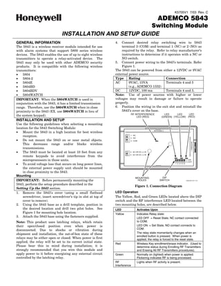
  • 1. K5705V1 7/03 Rev. C ADEMCO 5843 Switching Module INSTALLATION AND SETUP GUIDE GENERAL INFORMATION 4. Connect desired relay switching wire to 5843 The 5843 is a wireless receiver module intended for use terminal 3 (COM) and terminal 1 (NC) or 2 (NO) as with alarm systems that support 5800 series wireless required by the relay. Refer to relay manufacturer’s devices. The 5843 enables the use of up to eight wireless instructions to determine if it operates with a NC or transmitters to operate a relay-activated device. The NO switch. 5843 may only be used with other ADEMCO security 5. Connect power wiring to the 5843’s terminals. Refer products. It is compatible with the following wireless Figure 1. transmitters: The 5843 can be powered from either a 12VDC or 9VAC • 5804 external power source. • 5804-2 Type Rating Connection • 5804E AC 9VAC, 15VA Terminals 4 and 5 • 5804BD (e.g., ADEMCO 1332) • 5804BDV DC 12VDC, 100 ma Terminals 4 and 5. • 5804WATCH Note: Use of power sources with higher or lower IMPORTANT: When the 5804WATCH is used in voltages may result in damage or failure to operate conjunction with the 5843, it has a limited transmission properly. range. Therefore, use the 5804WATCH when in close 6. Position the wiring in the exit slot and reinstall the proximity to the 5843 (EX. use 5804WATCH in lieu of 5843’s cover on the base. RF INTERFERENCE LED LED LED the system keypad). LED (RED) (GREEN) (YELLOW) (RED) INSTALLATION AND SETUP Use the following guidelines when selecting a mounting location for the 5843 Switching Module: ANTENNA 2 • Mount the 5843 in a high location for best wireless reception. 1 - NC 2 - NO • Do not mount the 5843 on or near metal objects. 3 - COM ANTENNA 1 This decreases range and/or blocks wireless transmissions. • The 5843 must be located at least 10 feet from any 4 - AC OR DC (+) IN 5 - AC OR DC ( ) IN remote keypads to avoid interference from the microprocessors in those units. ON OFF • To avoid voltage loss that occurs on long power lines, 1 2 3 4 5 6 the external power supply unit should be mounted in close proximity to the 5843. Mounting MOUNTING DIP IMPORTANT: Before permanently mounting the HOLES SWITCH 5800GDO-001-V10 5843, perform the setup procedure described in the Figure 1. Connection Diagram Setting Up the 5843 section. 1. Remove the 5843's cover (using a small flathead LED Operation screwdriver, insert screwdriver’s tip in slot at top of The Yellow, Red, and Green LEDs located above the DIP cover to remove). switch and the RF interference LED located between the 2. Using the 5843 base as a drill template, position in two mounting holes, are described below. the desired location and drill two pilot holes. See LED Activates Upon Figure 1 for mounting hole location. Yellow Indicates Relay state: 3. Attach the 5843 base using the fasteners supplied. LED OFF = Reset State, NC contact connected Note: This product uses latching relays, which retain to COM. their open/closed position even when power is LED ON = Set State, NO contact connects to disconnected. Due to shocks or vibration during COM. shipment and installation, the out-of-box state of these The relay state momentarily changes when an enrolled button is pressed. When power is relays may be either open or closed. When power is first applied, the relay is forced to the reset state. applied, the relay will be set to its correct initial state. Red Wireless Key enrollment/erase indicator. (Used to Please bear this in mind during installation; it is determine status during Enrolling RF Transmitters strongly recommended that you wire this module and and Erasing All RF Transmitters procedures). apply power to it before energizing any external circuit Green Normally on (lighted) when power is applied. controlled by the latching relay. Flickering indicates RF is being processed. RF Lights when RF activity is present. Interference
  • 2. DIP Switch Settings 7. To add an additional button on the same key, repeat Normal operation of the 5843 requires all DIP switches be in step 6 for that button. the OFF position. 8. Place DIP switch 3 in the OFF position to accept the DIP switch 1 – Enables the Erasing All RF Transmitters Mode. button(s) enrolled. Refer to Erasing All RF Transmitters Section. 9. Repeat steps 4 through 8 to enroll additional DIP switch 2 – Enables the Enrolling RF Transmitters Mode. wireless transmitters. Refer to Enrolling RF Transmitters Section. 10. When all devices are enrolled, place DIP switch 2 in DIP switch 3 – Used during Enrolling RF Transmitters Mode. Refer to Enrolling RF Transmitters section. the OFF position. DIP switch 4 – 6 Used during Erasing All RF Transmitters ERASING ALL RF TRANSMITTERS 1 2 3 4 5 6 Notes: ON • To exit this procedure at any time, set DIP switch 1 OFF to the OFF position and wait 5 seconds before 5800GDO-002-V0 restarting procedure. ENROLLING RF TRANSMITTERS • Unless otherwise noted, the 5843 will automatically exit the Erasing All RF Transmitters Mode if each Notes: step is not accomplished within one minute of the • To exit the Transmitter Enrollment Mode at any previous step. time, set DIP switch 2 to the OFF position. • Unless otherwise noted, the 5843 will automatically 1. Place DIP switch 1 in the ON position. exit the Transmitter Enrollment Mode if each step is 2. Disconnect/reconnect power to the 5843. not accomplished within one minute of the other. Immediately after power is applied the following will • If during the enrollment procedure excessive RF occur: interference is noted as indicated by the RF • The green LED will turn on and remain on. Interference Indicator LED, it is advised that • If the EEPROM is not full, the red LED will flash on enrollment be exited until free of RF interference. and off once for each transmitter that can still be This will prevent inadvertent enrollment of an enrolled and then lights steady. outside wireless transmitter device. • If the EEPROM is full (8 wireless keys enrolled), the 1. Set all DIP switches to the OFF position. red LED remain on, indicating no more transmitters 2. Place DIP switch 2 in the ON position. can be enrolled. 3. Disconnect/reconnect power to the 5843. Immediately after power is applied the following will 3. Place all DIP switches opposite to their current occur: position within one minute of applying power in step • The green LED will turn on and remain on. 2. (All DIP switches must be switched opposite to • If the EEPROM is not full, the red LED will flash on their current position within 5 seconds of each other to avoid exiting this procedure.) and off once for each transmitter that can still be enrolled and then lights steady. 4. Return all DIP switches to their original positions • If the EEPROM is full (8 wireless keys enrolled), the and verify the red LED turns off. red LED will remain on, indicating that no more When the red LED turns off, all transmitters have transmitters can be enrolled. been erased. 4. If enrolling… Do this… SPECIFICATIONS An encrypted Press and hold all 4 buttons at Dimensions: transmitter (i.e. the same time. Verify that the 2-3/4” W x 4-15/16” H x 1-1/16” D. 5804E and red LED turns off. 5804WATCH) (70mm x 125mm x 27mm) A bi-directional Press and hold the B, C, & D Voltage: encrypted buttons at the same time. 12VDC OR transmitter (i.e. Verify that the red LED turns 9VAC, 15VA (use ADEMCO 1332 or equivalent) 5804BDV) off. Current: A non-encrypted Press the button to be enrolled 60mA transmitter (i.e., twice. Verify that the red Relay: 5804, 5804BD) LED turns off. One relay, with choice of normally open or normally 5. Place DIP switch 3 in the ON position. closed operation. 6. Press and release the button that will be used to Contact Ratings: 2 Amps at 28VDC. operate the switch. Verify the red LED flashes 3 Operating Temperature: times. 32° - 122°F (0° - 50°C) Note: If an incorrect wireless transmitter is enrolled, set DIP switch 3 to OFF and repeat the enrollment procedure from step 4. 2
  • 3. Federal Communications Commission (FCC) Part 15 The user shall not make any changes or modifications to the equipment unless authorized by the Installation Instructions or User's Manual. Unauthorized changes or modifications could void the user's authority to operate the equipment. CLASS B DIGITAL DEVICE STATEMENT NOTE: This equipment has been tested and found to comply with the limits for a Class B digital device, pursuant to part 15 of the FCC Rules. These limits are designed to provide reasonable protection against harmful interference in a residential installation. This equipment generates, uses and can radiate radio frequency energy and, if not installed and used in accordance with the instructions, may cause harmful interference to radio communications. However, there is no guarantee that interference will not occur in a particular installation. If this equipment does cause harmful interference to radio or television reception, which can be determined by turning the equipment off and on, the user is encouraged to try to correct the interference by one or more of the following measures: • Reorient or relocate the receiving antenna. • Increase the separation between the equipment and receiver. • Connect the equipment into an outlet on a circuit different from that to which the receiver is connected. • Consult the dealer or an experienced radio/TV technician for help. This Class B digital apparatus complies with Canadian ICES-003. Cet appareil numérique de la classe B est conforme à la norme NMB-003 du Canada. FCC/IC STATEMENT This device complies with Part 15 of the FCC rules and RSS 210 of Industry Canada. Operation is subject to the following two conditions: (1) This device may not cause harmful interference, and (2) This device must accept any interference received, including interference that may cause undesired operation. Cet appareil est conforme à la partie 15 des règles de la FCC & de RSS 210 des Industries Canada. Son fonctionnement est soumis aux conditions suivantes: (1) Cet appareil ne doit pas causer d' interferences nuisibles. (2) Cet appareil doit accepter toute interference reçue y compris les interferences causant une reception indésirable. 3
  • 4. For the latest warranty information, please go to: http://www.security.honeywell.com/hsc/resources/wa/index.html 2 Corporate Center Drive, Melville, NY 11747 Copyright © 2007 Honeywell International Inc. www.honeywell.com/security ÊK5705V1NŠ K5705V1 7/03 Rev. C