The document discusses the key considerations for designing hill road alignments. It covers definitions of hill roads, design issues specific to hill terrain like complex topography and weather. It outlines factors to consider in route selection, data required for design, and geometric design standards for elements like design speed, sight distance, curve radii, and cross-sections. The case study of NH-21 alignment in India is presented to illustrate hill road design challenges and solutions.
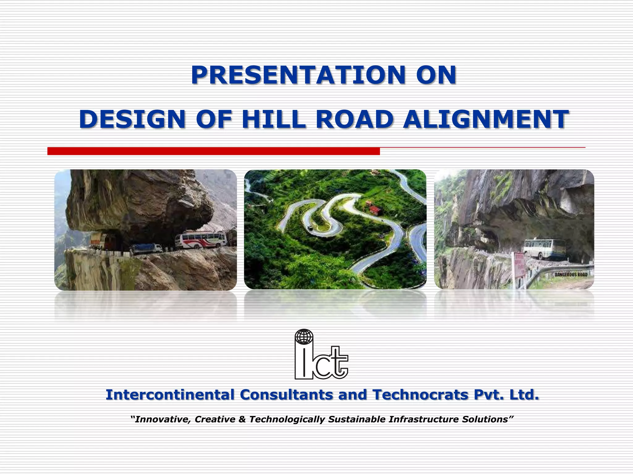
Intercontinental Consultants andTechnocrats Pvt. Ltd.
“Innovative, Creative & Technologically Sustainable Infrastructure Solutions”
PRESENTATION ON
DESIGN OF HILL ROAD ALIGNMENT
2.
Contents
Hill RoadDefinition
Design Issues in Hill Roads
Special Consideration in Hill Road Design
Route Selection
Engineering Data for Design
Geometric Design Standards
Design of Hair-pin Bends
Climbing Lane
Other Geometric Design Aspects
Case Study of NH-21 (Kiratpur Nerchowk Alignment)
2
3.
Hill Road Definition
Hill road is defined as the one which passes through
a terrain with a cross slope of 25% or more.
IRC:SP:73-2015 and IRC:SP:84-2014 have merged
the Mountainous and Steep Terrain having Cross
Slope more than 25%.
3
4.
Design Issues inHill Roads
Design and Construction of Hill roads are more complex than
in plain terrain due to factors summarized below:
Highly broken relief with vastly differing elevations and
steep slopes, deep gorges etc. which increases road length.
The geological condition varies from place to place.
Variation in hydro-geological conditions.
Variation in the climatic condition such as the change in
temperature due to altitude difference, pressure variation,
precipitation increases at greater height etc.
High-speed runoff due to the presence of steep cross slopes.
Filling may overload the weak soil underneath which may
trigger new slides.
Need of design of hairpin bends to attain heights.
Need to save Commercial and Residential establishments
close to the road.
Need to save the ecology of the hills.
4
5.
Special Consideration inHill Road Design
Alignment of Hill Roads
The designer should attempt to choose a short, easy,
economical and safe comforting route.
General considerations
When designing hill roads the route is located along
valleys, hill sides and if required over mountain passes.
Due to complex topography, the length of the route is
more.
In locating the alignment special consideration should be
made in respect to the variations in:
• Temperature
• Rainfall
• Atmospheric pressure and winds
• Geological conditions
• Resettlement and Rehabilitation considerations
• Environment Considerations
5
6.
Special Consideration inHill Road Design
Temperature
Air temperature in the hills is lower than in the valley. The
temperature drop being approximately 0.5° per 100 m of rising.
On slopes facing south and southwest snow disappears rapidly and
rain water evaporates quickly while on slopes facing north and
northeast rain water or snow may remain for the longer time.
Unequal warming of slopes, sharp temperature variations and
erosion by water are the causes of slope failure facing south and
southwest.
Rainfall
Rainfall generally increases with increase in height from sea level.
The maximum rainfall is in the zone of intensive cloud formation at 1500-
2500 m above sea level. Generally, the increase of rainfall for every 100 m
of elevation averages 40 to 60 mm.
In summer very heavy storms/cloud burst may occur in the hills and about
15 to 25% of the annual rainfall may occur in a single rainfall. The effects of
these types of rainfall are serious and should be considered in design.
Atmospheric pressure and winds
Atmospheric pressure decreases with increase in elevation.
At high altitudes, the wind velocities may reach up to 25-30 m/s and depth
of frost penetration is also 1.5 to 2 m.
Intensive weathering of rocks because of sharp temperature variations.
6
7.
Special Consideration inHill Road Design
Geological conditions
The inclination of folds may vary from horizontal to vertical
stratification of rock. These folds often have faults. Limestone or
sandstone folds may be interleaved with layers of clay which when
wetted may cause fracturing along their surface. This may result in
shear or slip fold.
The degree of stability of hill slopes depends on types of rock,
degree of strata inclination or dip, occurrence of clay seams, the
hardness of the rocks and presence of ground water.
When locating the route an engineer must study the details of
geological conditions of that area and follow stable hill slopes where
no ground water, landslides, and unstable folds occur.
Resettlement and Rehabilitation
Due to limited availability of flat areas and connectivity issues, most
of the residential and commercial activity happens very close to the
road leading to large scale R&R and becomes a challenge in
alignment design.
Environment
Hills are ecologically sensitive areas relatively untouched by human
activity. The alignment design must attempt to minimize tree cutting
and large scale earth filling/cutting to minimize damage.
7
8.
Route Selection
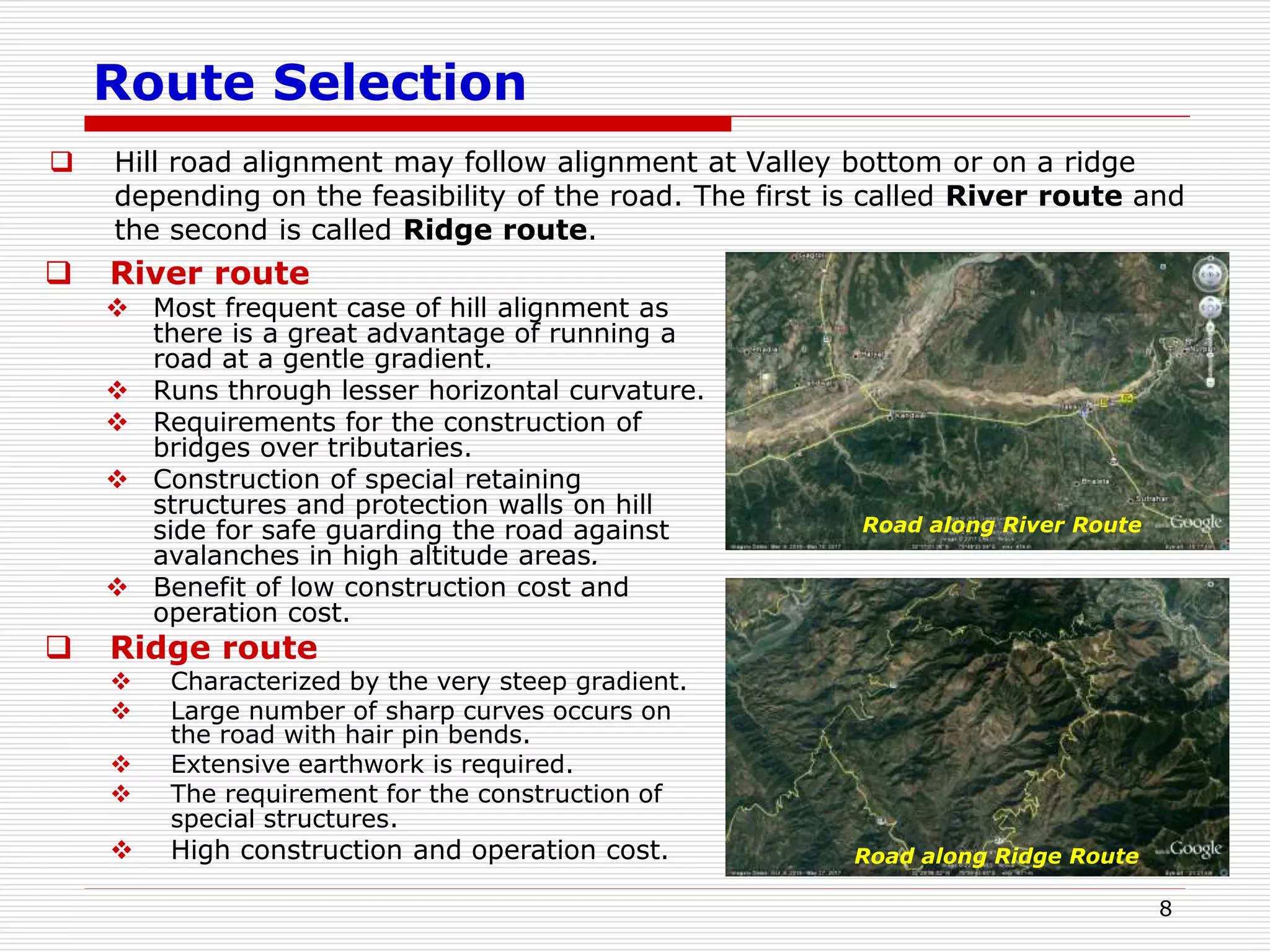
Hillroad alignment may follow alignment at Valley bottom or on a ridge
depending on the feasibility of the road. The first is called River route and
the second is called Ridge route.
8
River route
Most frequent case of hill alignment as
there is a great advantage of running a
road at a gentle gradient.
Runs through lesser horizontal curvature.
Requirements for the construction of
bridges over tributaries.
Construction of special retaining
structures and protection walls on hill
side for safe guarding the road against
avalanches in high altitude areas.
Benefit of low construction cost and
operation cost.
Ridge route
Characterized by the very steep gradient.
Large number of sharp curves occurs on
the road with hair pin bends.
Extensive earthwork is required.
The requirement for the construction of
special structures.
High construction and operation cost.
Road along River Route
Road along Ridge Route
9.
Engineering Data forDesign
The design data includes:
The terrain classification all along the alignment - to be established through
topographic data/ Contours of the area using Satellite Imagery.
All features like river course, streams, cross-drainage structures (for
existing alignment), flooding areas, high flood levels, landslide areas,
snow/avalanche prone areas etc.
9
River Morphology and Regime data.
Chainage wise inventory of the side
slope material type i.e. soil with
classification and properties, rock
type and its structural geology of
the area.
Hydrological data for all stream and
river crossings.
Available material and resources
that can be used in the road
construction.
Geometric standards. Contour Data for Design
10.
Geometric Design Standards
The various Design Standards being followed in the India
for the design of Hill Road are:
IRC:SP:48-1998 Hill Road Manual.
IRC:52-2001 Recommendations About the Alignment
Survey and Geometric Design of Hill Roads.
IRC:SP:91-2010 Guidelines for Road Tunnels.
IRC:SP:73-2015 Manual of Specifications and
Standards for Two Laning of Highways with Paved
Shoulder.
IRC:SP:84-2014 Manual of Specifications and
Standards for Four Laning of Highways through
Public Private Partnership.
10
11.
Geometric Design Standards
Hill Road Capacity
11
Type of Road
Design Service Volume in PCU per day
As per IRC:SP:48-1998 and
IRC:52- 2001
As per IRC:SP:73-2015 &
IRC:SP:84-2014
For Low
Curvature
(0-200 degrees
per km)
For High
Curvature
(above 0-200
degrees per km)
Level of
Service ‘B’
Level of
Service ‘C’
Single lane 1,600 1,400 - -
Intermediate
lane
5,200 4,500 - -
Two Lane 7,000 5,000 9,000 -
Four Lane - - 20,000 30,000
12.
Geometric Design Standards
Design Speed:
The design speed for various categories of hill roads are
given below:
12
Road
Classification
As per IRC:SP:48-1998 and IRC:52-
2001
As per IRC:SP:73-
2015 & IRC:SP:84-
2014
Mountainous
Terrain
Steep Terrain
Mountainous and
Steep Terrain
Ruling Minimum Ruling Minimum Ruling Minimum
National and
State Highways
50 40 40 30 60 40
Major District
Roads
40 30 30 20 - -
Other District
Roads
30 25 25 20 - -
Village Roads 25 20 25 20 - -
13.
Geometric Design Standards
Sight Distance:
Visibility is an important requirement for safety on roads.
It is necessary that sight distance of sufficient length is available to permit
drivers enough time and distance to stop their vehicles to avoid accidents.
13
Design
Speed
(Km/h)
As per IRC:SP:48-1998 and
IRC:52- 2001
As per IRC:SP:73-2015 &
IRC:SP:84-2014
Mountainous and Steep Terrain
Stopping
Sight
Distance (m)
Intermediate
Sight Distance
(m)
Safe Stopping
Sight Distance
(m)
Desirable
Minimum Sight
Distance (m)
20 20 40 - -
25 25 50 - -
30 30 60 - -
35 40 80 - -
40 45 90 45 90
50 60 120 60 120
60 - - 90 180
14.
Geometric Design Standards
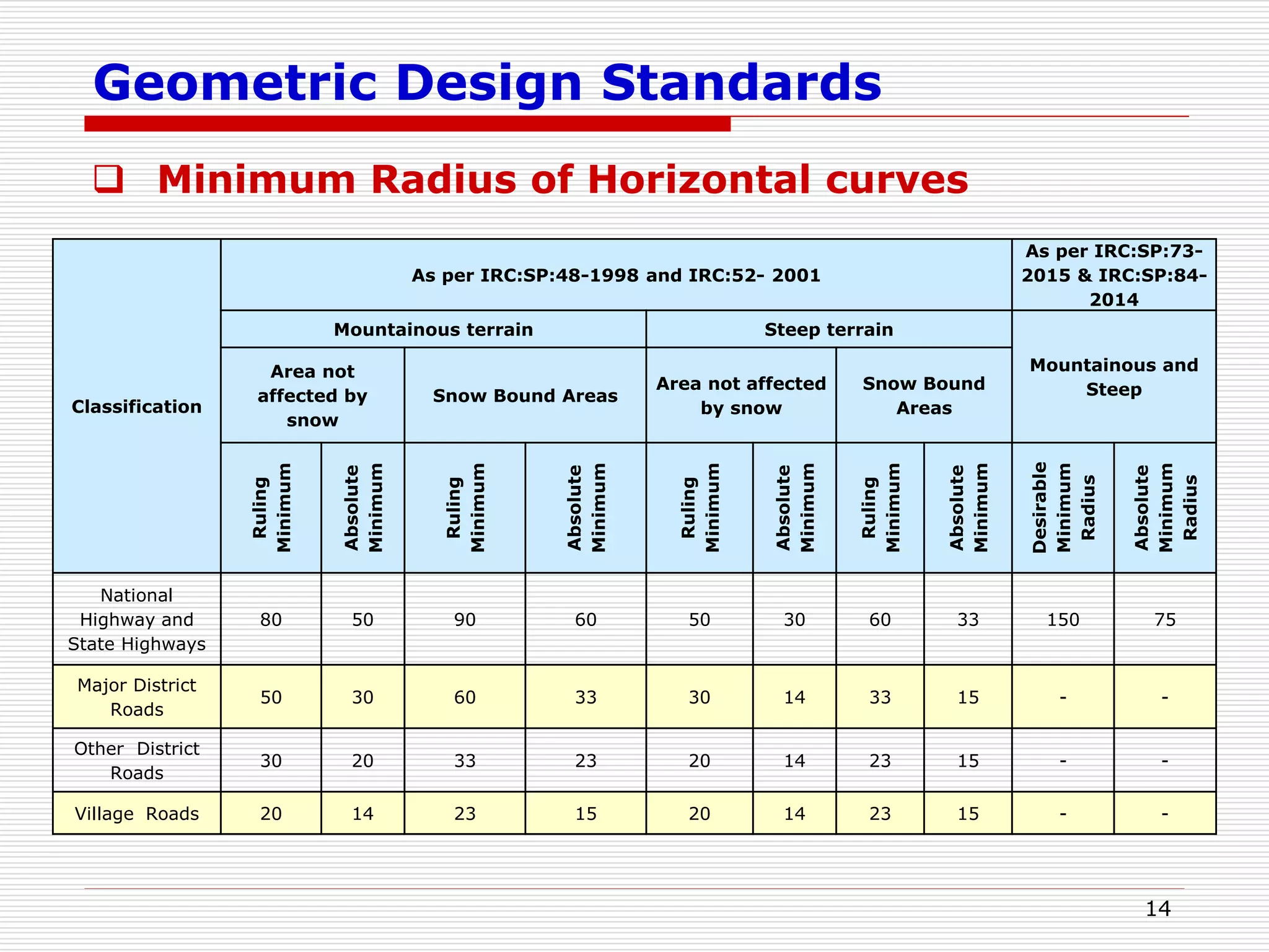
Minimum Radius of Horizontal curves
14
Classification
As per IRC:SP:48-1998 and IRC:52- 2001
As per IRC:SP:73-
2015 & IRC:SP:84-
2014
Mountainous terrain Steep terrain
Mountainous and
Steep
Area not
affected by
snow
Snow Bound Areas
Area not affected
by snow
Snow Bound
Areas
Ruling
Minimum
Absolute
Minimum
Ruling
Minimum
Absolute
Minimum
Ruling
Minimum
Absolute
Minimum
Ruling
Minimum
Absolute
Minimum
Desirable
Minimum
Radius
Absolute
Minimum
Radius
National
Highway and
State Highways
80 50 90 60 50 30 60 33 150 75
Major District
Roads
50 30 60 33 30 14 33 15 - -
Other District
Roads
30 20 33 23 20 14 23 15 - -
Village Roads 20 14 23 15 20 14 23 15 - -
15.
Geometric Design Standards
Typical Cross-sections – 2 lane carriageway
(as per IRC:SP:73-2015)
15
Road Classification Carriageway Width (m) Shoulder Width (m)
National and State Highways
i) Single lane 3.75 2 x 1.25
ii) Double Lane 7.00 2 x 0.9
Major District Roads and Other District Roads 3.75 2 x 0.5
Village Roads 3.00 2 x 0.5
As per IRC:SP:48-1998 and IRC:52- 2001
16.
16
Geometric Design Standards
Typical Cross-sections – 4 Lane Carriageway Widening
Towards Valley Side (as per IRC:SP:84-2014)
17.
17
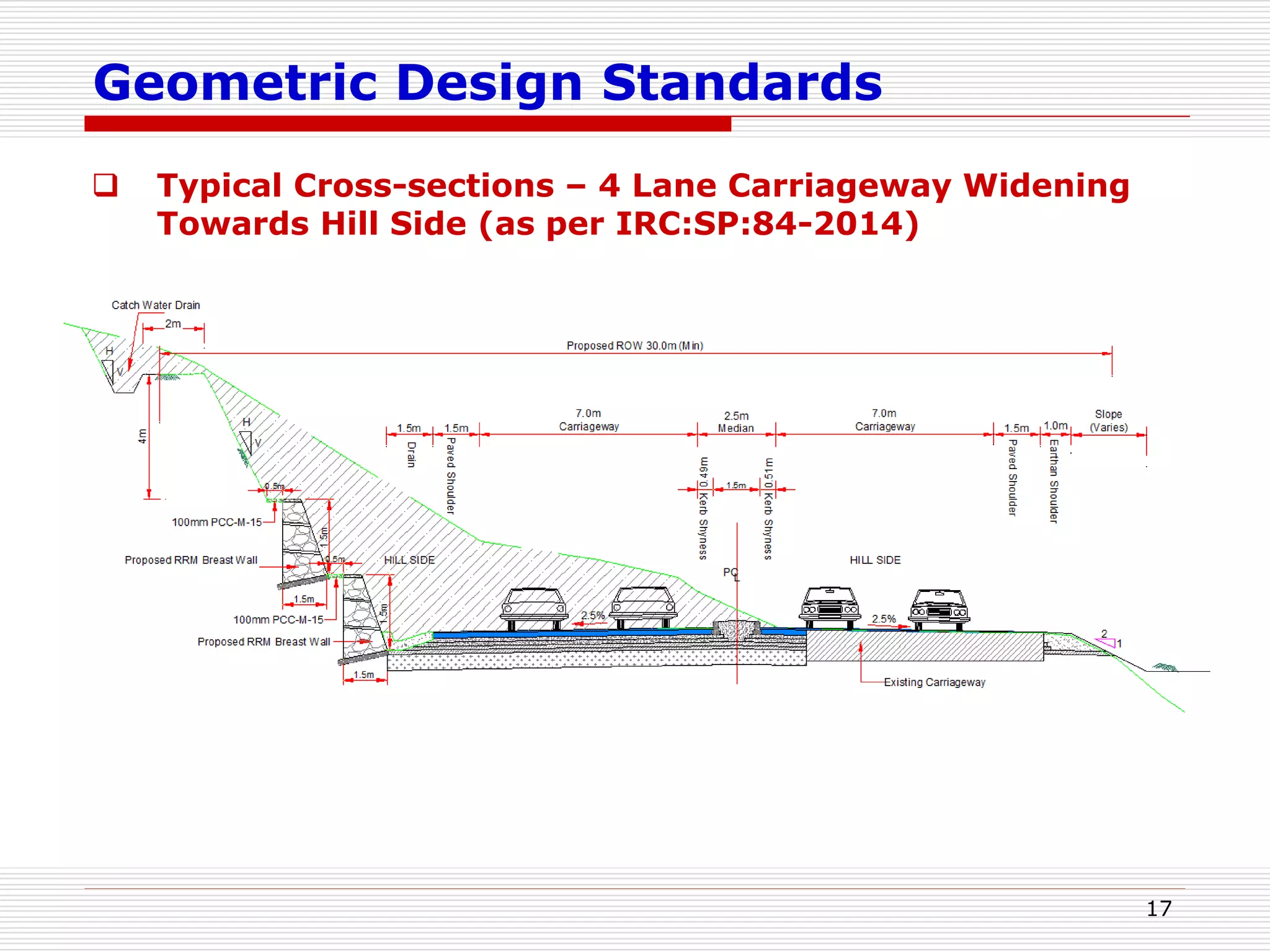
Geometric Design Standards
Typical Cross-sections – 4 Lane Carriageway Widening
Towards Hill Side (as per IRC:SP:84-2014)
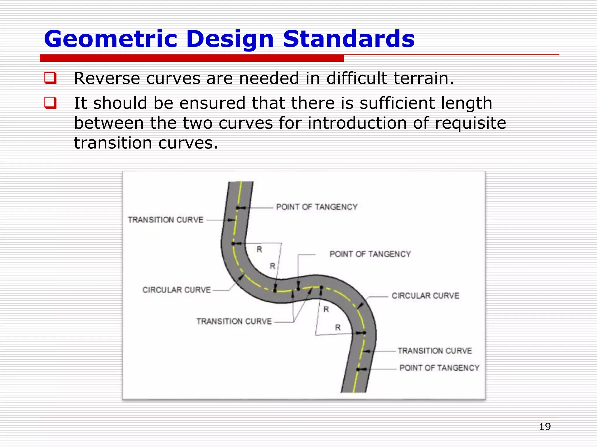
Geometric Design Standards
Reverse curves are needed in difficult terrain.
It should be ensured that there is sufficient length
between the two curves for introduction of requisite
transition curves.
19
20.
Geometric Design Standards
Curves in same direction separated by short tangents, known
as broken – back curves.
Should be avoided, as far as possible, in the interest of
aesthetics and safety and replaced by a single curve.
If this is not feasible, a tangent length corresponding to 10
seconds travel time must at least be ensured between the two
curves.
20
21.
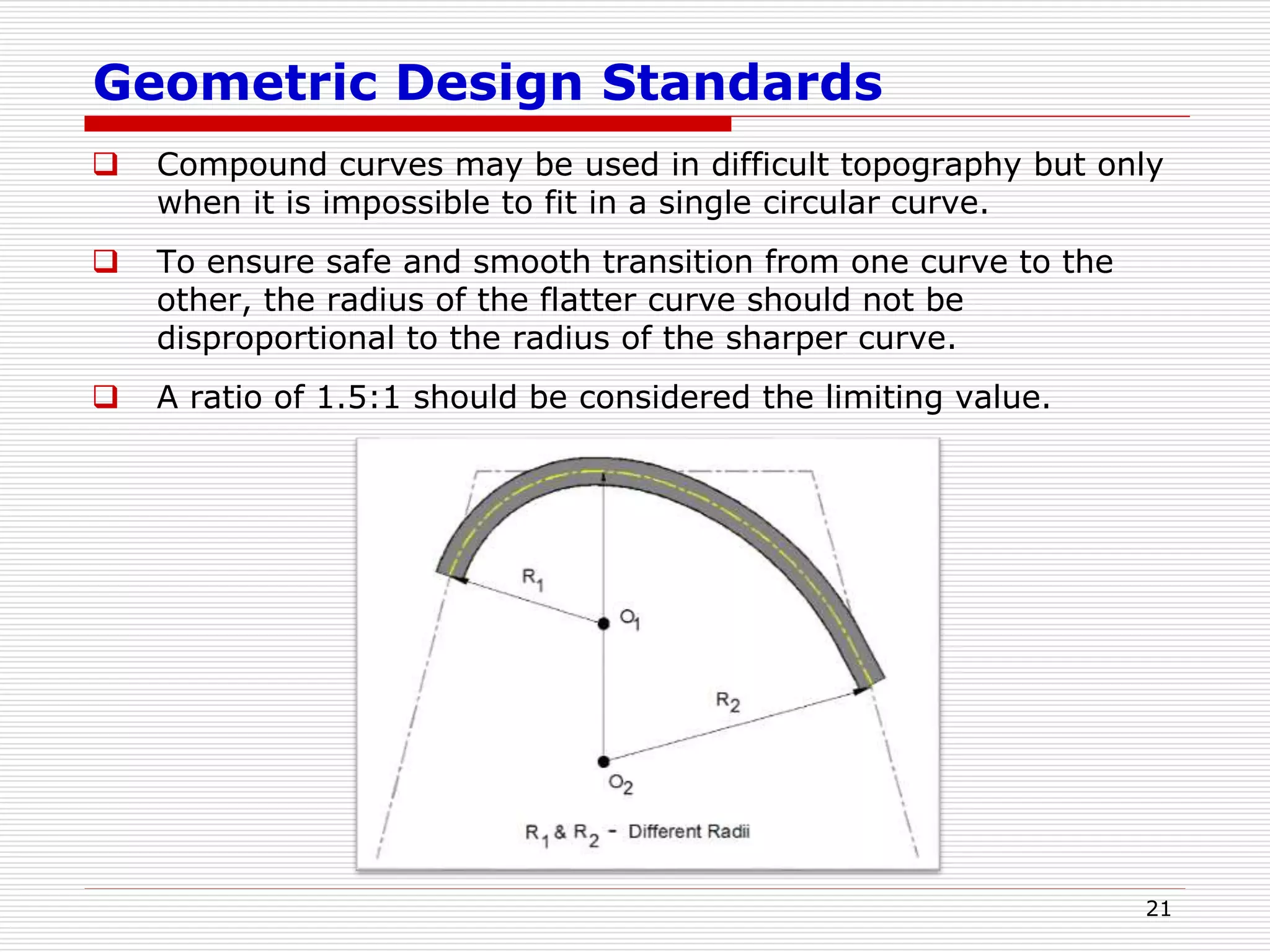
Geometric Design Standards
Compound curves may be used in difficult topography but only
when it is impossible to fit in a single circular curve.
To ensure safe and smooth transition from one curve to the
other, the radius of the flatter curve should not be
disproportional to the radius of the sharper curve.
A ratio of 1.5:1 should be considered the limiting value.
21
22.
Geometric Design Standards
Set Back Distance
Requisite sight distance should be available to sight
the inside of horizontal curves.
Lack of visibility in the lateral direction may arise due
to obstruction like walls cut, slopes, wooded areas,
high crops etc.
22
23.
Geometric Design Standards
Vision Berm
Where there is a cut
slope on the inside of the
horizontal curve, the
average height of sight
line can be used as an
approximation for
deciding the extent of
clearance.
Cut slope shall be kept
lower than this height at
the line demarcating the
set back distance
envelop, either by cutting
back the slope or
benching suitably, which
is also generally known
as vision berm.
23
24.
Geometric Design Standards
Vertical Alignment
The vertical alignment of a hill road need to be adaptive
by:
• Adopting mild vertical grades for reduced potential for
erosion of road bed.
• Designing vertical profile compatible with natural topography
for optimum and balanced cut-fill quantities hence generate
less spoil.
• Keeping finished road level and fill slopes higher than the high
flood level (HFL).
• Avoiding interception with water table line which cause wet
pavement layers.
• Optimizing the cut height at landslide and rock fall prone
areas.
• Ensure Easy Access to Properties.
• Ensure Safer Junction Design.
24
25.
Geometric Design Standards
Vertical Alignment
Vertical curves are introduced for smooth transition at grade
change.
Both Summit curves and Valley curves should be designed as
Square parabola.
The Length of vertical curves is controlled by sight distance
requirements.
Curves with greater length are aesthetically better.
Recommended gradients for different terrain conditions, except at
hair pin bends, are given below:
25
As per IRC:SP:48-1998 and
IRC:52- 2001
As per IRC:SP:73 &
IRC:SP:84
Classification of
Gradient
Mountainous Terrain
and Steep Terrain more
than 3000 m above
MSL
Steep Terrain
up to 3000 m
above MSL
Mountainous Steep
Ruling Gradient 5% 6% 5% 6%
Limiting Gradient 6% 7% 6% 7%
Exceptional 7% 8% - -
26.
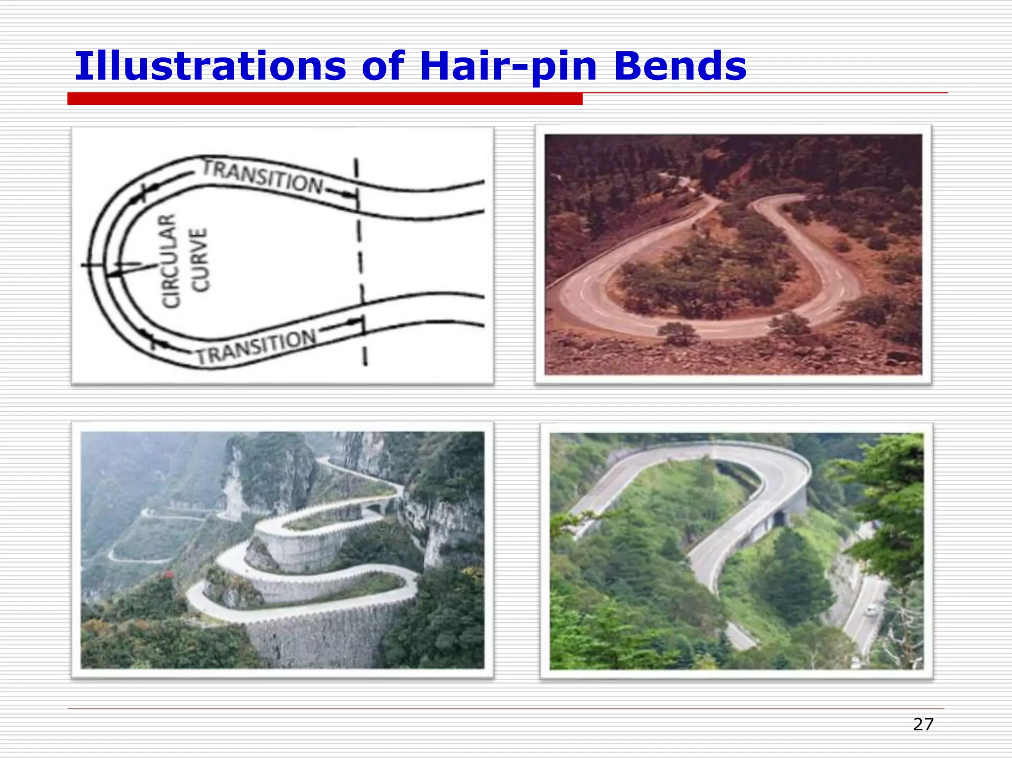
Design of Hair-pinBends
At unavoidable circumstances Hair-pin Bends may be designed
as Circular Curve with Transitions or as Compound Circular
curves.
26
Design Criteria for Hair-pin Bends As per IRC:SP:48-1998 and IRC:52- 2001
Description Criteria
Min Design Speed 20 Km/h
Min Roadway width at apex
NH/SH
11.5m (Double lane)
9.0m (Single lane)
MDR/ODR 7.5m
Village Roads 6.5m
Min radius for the inner curve 14 m
Min Length of transition Curve 15 m
Gradient
Maximum 1 in 40 (2.5%)
Minimum 1 in 200 (0.5%)
Max Super elevation 1 in 10 (10%)
Minimum Intervening distance between the successive hair
pin bends
60m
Climbing Lane
ClimbingLane shall be provided in order to address the
necessity of making available separate lane for safe overtaking
for vehicle travelling uphill.
IRC:52-2001, IRC:SP:73-2015 and IRC:SP:84-2014 mandates
for provision of Climbing lanes but no warrants are provided.
AASHTO provides the guidelines for the provision of Climbing
lanes:
Up Grade traffic flow rate in excess of 200 vehicles per hour.
Up Grade truck flow rate in excess of 20 vehicles per hour.
One of the following conditions exists:
• A 15 km/h [10 mph] or greater speed reduction is expected for a typical
heavy truck.
• Level of Service ‘E’ or ‘F’ exists on the grade.
• A reduction of two or more levels of service is experienced when moving
from the approach segment to grade.
In addition, safety considerations may justify the addition of a
climbing lane regardless of grade or traffic volumes.
28
29.
Other Geometric DesignAspects
Escape Lane
Grade Compensation at Curves
Passing Places
Vertical and lateral Clearances
Widening at Curves
Co-ordination of Horizontal and
Vertical Alignments
Tunnels
29
Escape lane
Passing Places Widening at Curves
30.
Typical Section forTunnels
30
Typical Cross section for 3-lane Tunnel as per IRC SP 91-2010
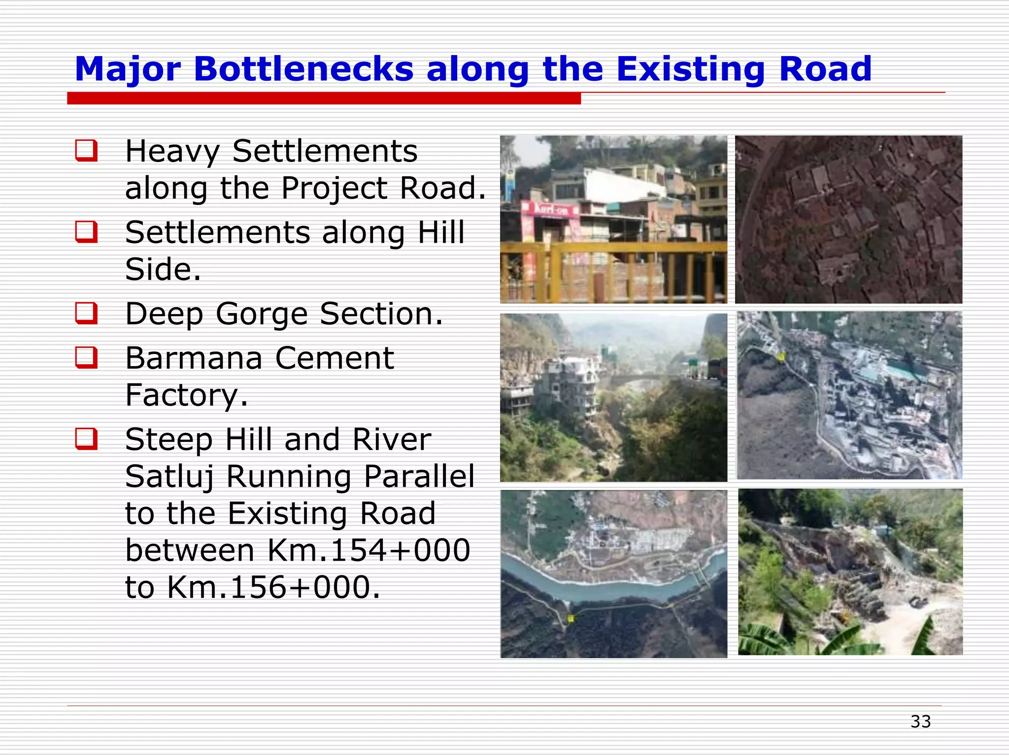
Major Bottlenecks alongthe Existing Road
Heavy Settlements
along the Project Road.
Settlements along Hill
Side.
Deep Gorge Section.
Barmana Cement
Factory.
Steep Hill and River
Satluj Running Parallel
to the Existing Road
between Km.154+000
to Km.156+000.
33
34.
Major Bottlenecks alongthe Existing Road
Bridge across River
Satluj at Km 157+000
Sharp hair pin bends
Steep grade section
Sundar Nagar lake
34
35.
Capacity Augmentation –Base Year Traffic
35
Station
No.
Chainage
(km)
Location of
Survey
ADT
Peak Hour
Flows
Peak
Hour
proportion
in
daily
Vehicle
Vol.
Peak
Hour
proportion
in
daily
PCU
Vol.
Veh’s PCUs Veh’s PCUs
MCC-1 138+500
Bamta
Village
5439 9841 324 547 5.96 5.56
MCC-2 167+000 Zedol Village 6526 9914 412 542 6.31 5.47
36.
Key Plan
36
Tunnel Length(Km)
T1 1.75
T2 0.65
T3 0.4
T4 1.41
T5 0.86
Total 5.07
Length of Existing Alignment = 116.80 Km,
Length of Revised Alignment = 84.38 Km,
Saving in Length = 32.42 Km
T5
T4
T3
T2
T1
37.
Salient Features ofthe Project
Capacity Augmentation/
Development Scope
4 Laning
Major Bridges
15 nos., Longest Bridge of 650m over
Govind Sagar lake
Proposed Bypasses
2 (Sunder nagar Bypass – 5.678 Km, Ner
Chowk Bypass – 4.551 Km)
Major Realignments
New alignment along Govind Sagar
Lake/Satluj Beas River – 32.570 Km
Tunnels 5 nos. for Total length of 5.07 Km
Toll Plazas 2 nos.
Total Civil Cost INR 1818.47 Cr. (Rs. 21.64 Cr/km)
37


![Climbing Lane
Climbing Lane shall be provided in order to address the
necessity of making available separate lane for safe overtaking
for vehicle travelling uphill.
IRC:52-2001, IRC:SP:73-2015 and IRC:SP:84-2014 mandates
for provision of Climbing lanes but no warrants are provided.
AASHTO provides the guidelines for the provision of Climbing
lanes:
Up Grade traffic flow rate in excess of 200 vehicles per hour.
Up Grade truck flow rate in excess of 20 vehicles per hour.
One of the following conditions exists:
• A 15 km/h [10 mph] or greater speed reduction is expected for a typical
heavy truck.
• Level of Service ‘E’ or ‘F’ exists on the grade.
• A reduction of two or more levels of service is experienced when moving
from the approach segment to grade.
In addition, safety considerations may justify the addition of a
climbing lane regardless of grade or traffic volumes.
28](https://image.slidesharecdn.com/hillroadspart-1geometricdesignofhillroad18817-230801101858-57b1fd42/75/Hill_Roads_Part-1_Geometric_Design_of_Hill_Road_18817-ppt-28-2048.jpg)