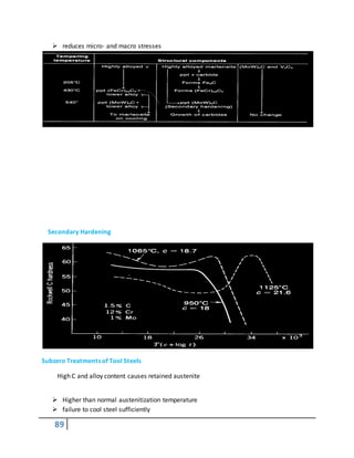
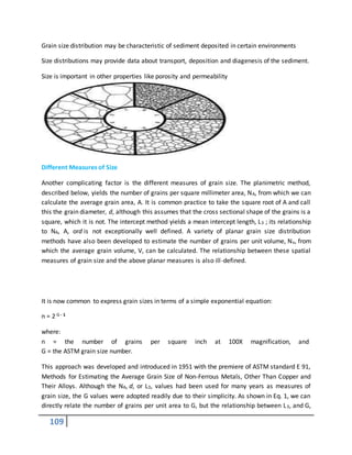
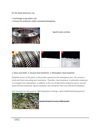
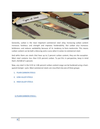
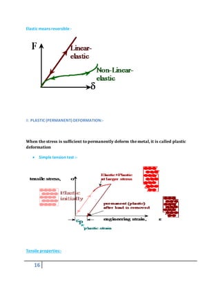
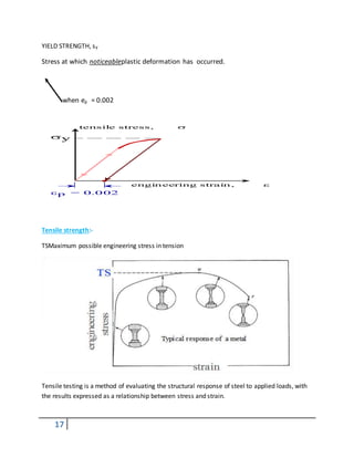
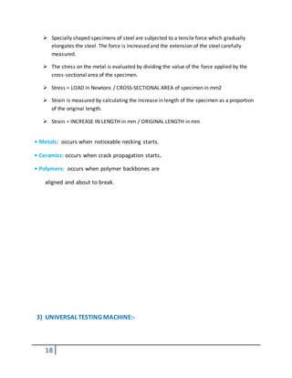
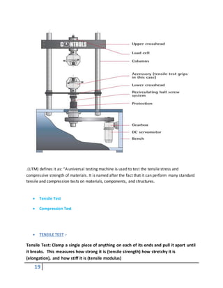
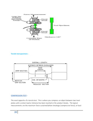
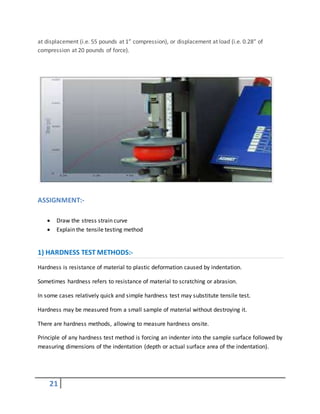
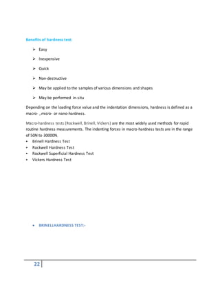
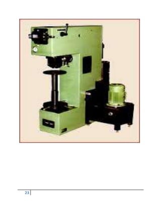
The document discusses various types of engineering materials including metals and their classification. It begins by introducing metallic materials and their properties. It then discusses the two main categories of metals - ferrous and non-ferrous metals. Ferrous metals contain iron while non-ferrous metals do not. The document further discusses various ferrous metals like steel and its alloys. It also discusses common non-ferrous metals like aluminum, zinc and copper. The classification of materials into ferrous and non-ferrous is described. Mechanical properties testing methods like tensile testing and hardness testing are also summarized.


![51
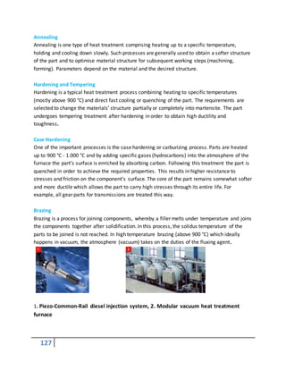
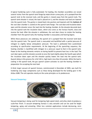
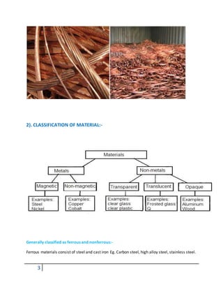
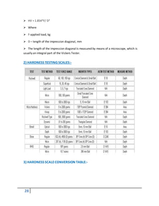
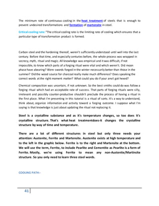
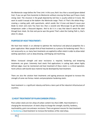
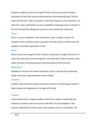
2) QUENCHING MEDIA DURING THEHEAT TREATMENT
Quenching media is very important to hardening because it is a very effective of hardness of
the material
quenching medias:
Water:
water is fairly good quenching medium. It is cheap, readily available, easily stored nontoxic
nonflammable smokeless and easy to filer and pump but with water quench the formation of
bubbles may cause soft spots in the metal. Agitation is recommended with use of water
quench. Still other problems with water quench include its oxidizing nature, its corrosivity and
the tendency to excessive distortion and cracking although this bad properties for plain carbon
steels.
Brine (salt water): Brine is a more severe quench medium than water. Unfortunately it tends to
accelerate corrosion problems unless completely removed. Sodium or potassium hydroxide can
be used when very severe quenching is desired and one wishes to obtain good hardness in low
carbon steels
]
Oil: When slower cooling rate is desired oil quenches can be employed. The slower cooling
through the ms to mf temperature range leads to a milder temperature gradient and a reduced
likelihood of cracking. Problems associated with quenchants include water contamination,
smoke and fire hazards. In addition quench oils tend to be somewhat expensive.
Air: Low alloy steels in light sections and high alloy steels may be successfully hardened by
means of compressed air or still air. The advantages of using air are that distortion is negligible
and that the steel can easily be straightened during cooling process. One drawback here is that
the surface may be oxidized the cooling.](https://image.slidesharecdn.com/heattreatmentcoursematerial-151029200318-lva1-app6892/85/Heat-treatment-course-material-51-320.jpg)
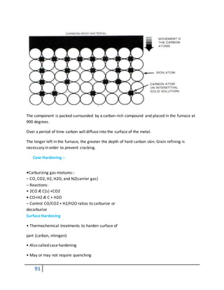
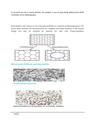
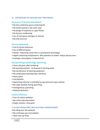
![61
.
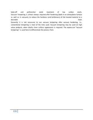
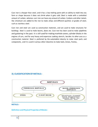
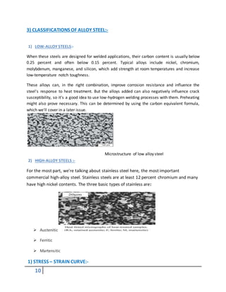
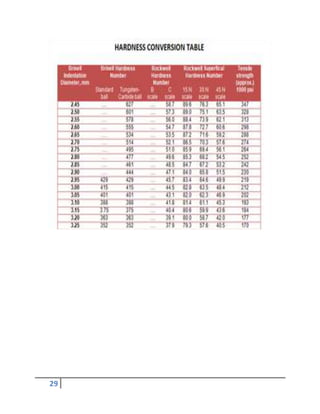
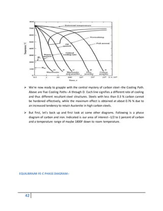
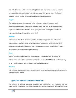
picture of decarb zone
2) CAUSES OF DECARBURIZATION:-
Chemical reactions
The most common reactions are:
also called the Boudouard reaction
Other reactions are[1]](https://image.slidesharecdn.com/heattreatmentcoursematerial-151029200318-lva1-app6892/85/Heat-treatment-course-material-61-320.jpg)
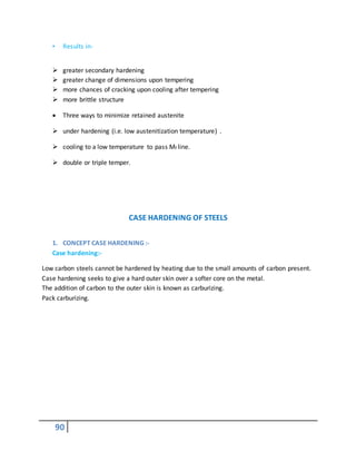
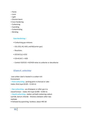
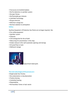
![65
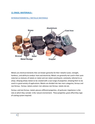
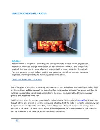
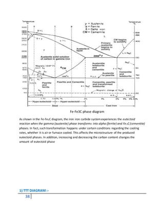
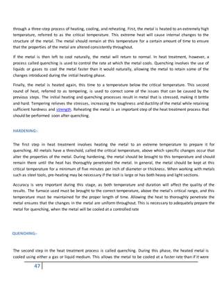
combined addition of vanadium and molybdenum was found to be the most effective for the
improvement of hardness without causing an increase in the thermal expansion coefficient.
Without heat treatment, the hardness value increased up to 180 HB, and the thermal expansion
coefficient was kept at a relatively low value of 4.6 × 10⁻⁶ K−1 with a combined addition of 4.6
wt% V and 3.8 wt% Mo. The effects on the damping capacity of graphite morphology, the
magnetic domain, and the combined addition of vanadium and molybdenum were also
investigated. The good damping capacity of Invar-type cast irons was mainly the result of stress
absorption in graphite. As the amounts of vanadium
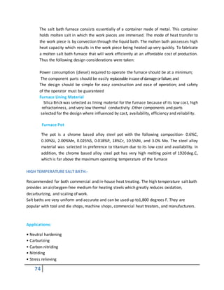
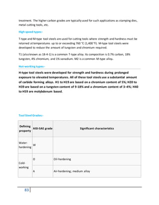
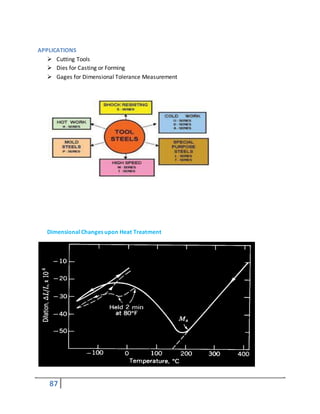
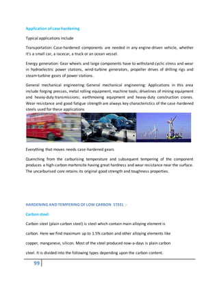
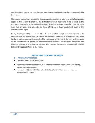
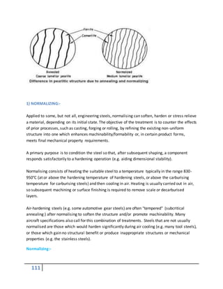
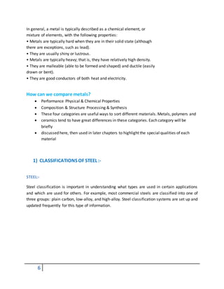
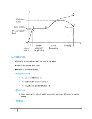
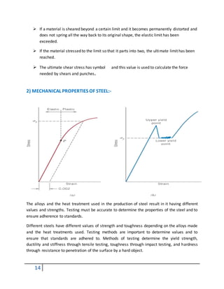
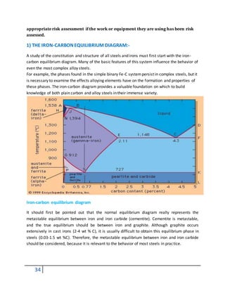
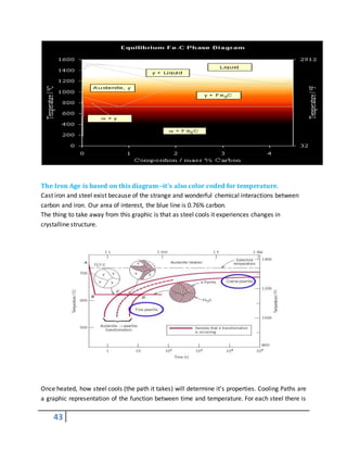
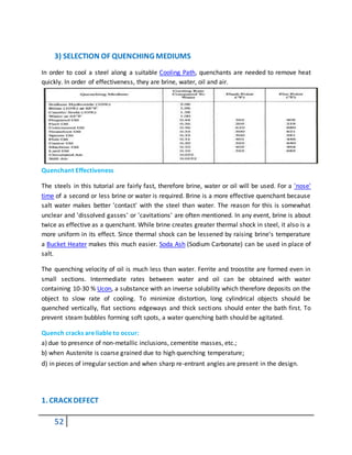
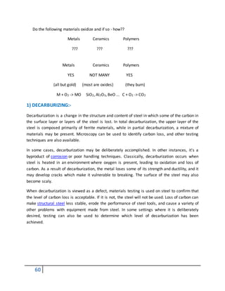
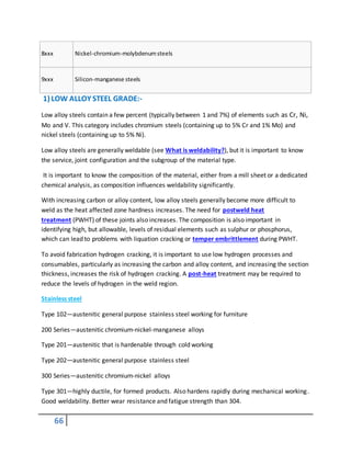
Major classifications of steel[2]
SAE
designation
Type
1xxx Carbonsteels
2xxx Nickel steels
3xxx Nickel-chromiumsteels
4xxx Molybdenumsteels
5xxx Chromiumsteels
6xxx Chromium-vanadiumsteels
7xxx Tungstensteels](https://image.slidesharecdn.com/heattreatmentcoursematerial-151029200318-lva1-app6892/85/Heat-treatment-course-material-65-320.jpg)
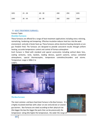
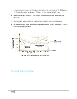
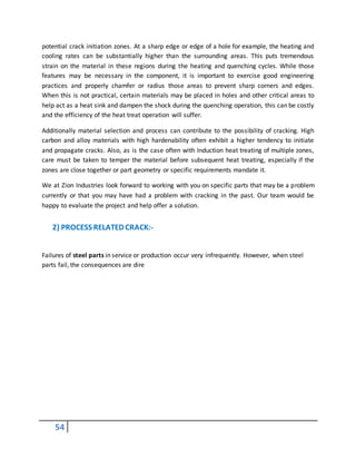
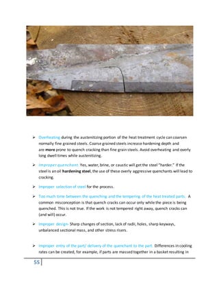
![67
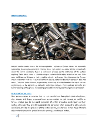
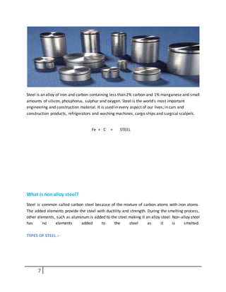
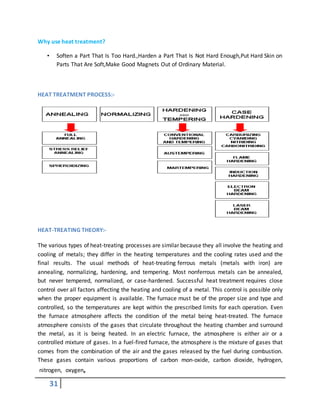
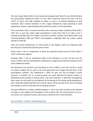
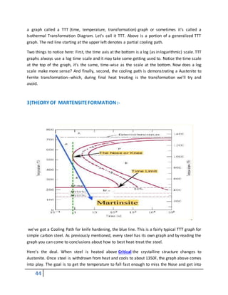
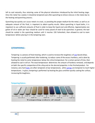
Type 302—same corrosion resistance as 304, with slightly higher strength due to additional
carbon.
Type 303—free machining version of 304 via addition of sulfur and phosphorus. Type 304—the
most common grade; the classic 18/8 (18% chromium, 8% nickel) stainless steel. Outside of the
US it is commonly known as "A2 stainless steel",
Type 304L—same as the 304 grade but lower carbon content to increase weldability. Is slightly
weaker than 304.
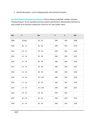
2)CHEMICAL COMPOSITIONOF LOWALLOY STEEL GRADES:-
The American Iron and Steel Institute (AISI) defines carbon steel as follows: Steel is considered
to be carbon steel when no minimum content is specified or required for chromium, cobalt,
columbium [niobium], molybdenum, nickel, titanium, tungsten, vanadium or zirconium, or any
other element to be added to obtain a desired alloying effect; when the specified minimum for
copper does not exceed 0.40 per cent; or when the maximum content specified for any of the
following elements does not exceed the percentages noted: manganese 1.65, silicon 0.60,
copper 0.60.
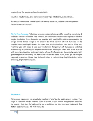
Steels can be classified by a variety of different systems depending on:
The composition, such as carbon, low-alloy or stainless steel.
The manufacturing methods, such as open hearth, basic oxygen process, or
electric furnace methods.
The finishing method, such as hot rolling or cold rolling
The product form, such as bar plate, sheet, strip, tubing or structural shape
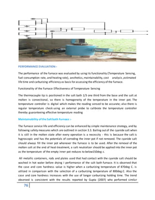
The deoxidation practice, such as killed, semi-killed, capped or rimmed steel
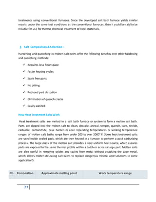
The microstructure, such as ferritic, pearlitic and martensitic
The required strength level, as specified in ASTM standards
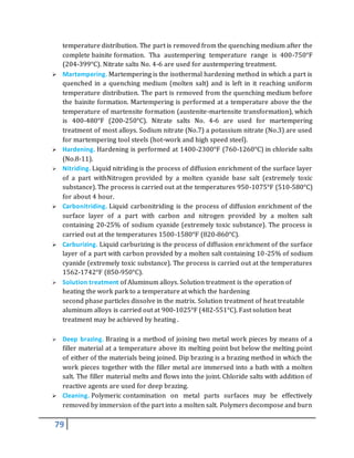
The heat treatment, such as annealing, quenching and tempering, and
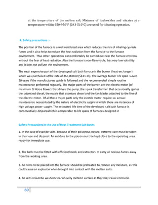
thermomechanical processing](https://image.slidesharecdn.com/heattreatmentcoursematerial-151029200318-lva1-app6892/85/Heat-treatment-course-material-67-320.jpg)