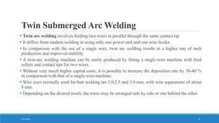
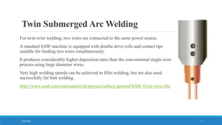
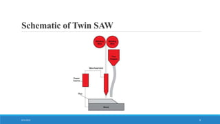
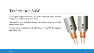
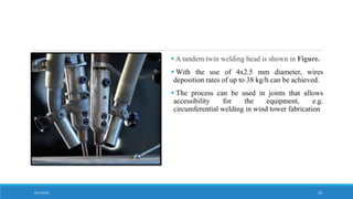
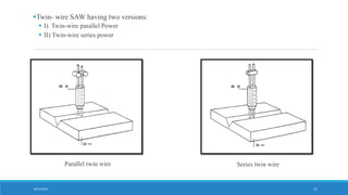
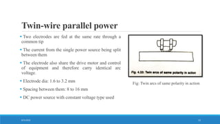
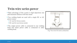
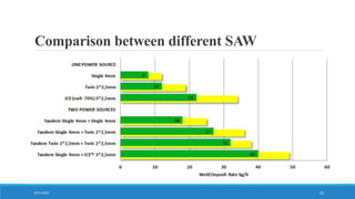
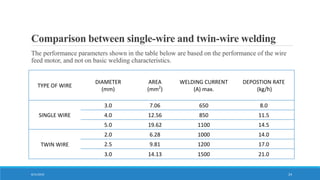
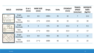
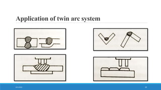
Twin Submerged Arc Welding
13BME081
13BME082
13BME083
13BME084
13BME086
8/31/2016 1
Submerged Arc Welding
 The modern SAW is an arc welding process, in which one or more arcs formed between one or
more bare wire electrodes and the work piece provides the heat coalescence.
 Are is completely submerged under a blanket of granular, fusible flux.
 Fully automatic or semi automatic process
8/31/2016 2
Submerged Arc Welding
 Fully Automatic
◦ Flux fed mechanically ahead of the arc
◦ Wire fed automatically
◦ Arc length controlled automatically
 Semi automatic
◦ Wire feed and arc length control automatically
◦ Welder moves the welding gun
◦ Flux feed may be by gravity flow
8/31/2016 3
Submerged Arc Welding Methods
1. • Single-wire welding
2. • Twin-arc welding
3. • Tandem welding
4. • Tandem Twin welding
5. • Strip welding
6. • Narrow gap welding
7. • Cold wire addition
8/31/2016 4
Basic Equipment
 A wire feeder to drive the electrode to the work through the
contact tube of welding gun or welding head
 A welding power source to supply electric current to the
electrode at the contact tube
 An arrangement for holding the flux and feeding it ahead of the
arc
 A means of traversing the weld joint
8/31/2016 5
Twin torch
Twin Submerged Arc Welding
8/31/2016 6
 Twin arc welding involves feeding two wires in parallel through the same contact tip.
 It differs from tandem welding in using only one power unit and one wire feeder.
 In comparison with the use of a single wire, twin arc welding results in a higher rate of melt
production and improved stability.
 A twin-arc welding machine can be easily produced by fitting a single-wire machine with feed
rollers and contact tips for two wires.
 Without very much higher capital costs, it is possible to increase the deposition rate by 30-40 %
in comparison with that of a single-wire machine.
 Wire sizes normally used for butt welding are 2.0,2.5 and 3.0 mm, with wire separations of about
8 mm.
 Depending on the desired result, the wires may be arranged side by side or one behind the other.
Twin Submerged Arc Welding
For twin-wire welding, two wires are connected to the same power source.
A standard SAW machine is equipped with double drive rolls and contact tips
suitable for feeding two wires simultaneously.
It produces considerably higher deposition rates than the conventional single-wire
process using large diameter wires.
Very high welding speeds can be achieved in fillet welding, but are also used
successfully for butt welding.
http://www.esab.com/automation/en/process/subarc-general/SAW-Twin-wire.cfm
8/31/2016 7
Schematic of Twin SAW
8/31/2016 8
Tandem twin SAW
 For higher deposition rates, it can be obtained when tandem
welding is combined with twin wires.
 The tandem twin process is simply a combination of tandem and
twin-wire welding.
 It can use a combination of DC(+)/AC or AC/AC for greater
deposition rate.
8/31/2016 9
 A tandem twin welding head is shown in Figure.
 With the use of 4x2.5 mm diameter, wires
deposition rates of up to 38 kg/h can be achieved.
 The process can be used in joints that allows
accessibility for the equipment, e.g.
circumferential welding in wind tower fabrication
8/31/2016 10
Parallel twin wire Series twin wire
8/31/2016 11
Twin- wire SAW having two versions:
 I) Twin-wire parallel Power
 II) Twin-wire series power
Twin-wire parallel power
 Two electrodes are fed at the same rate through a
common tip
 The current from the single power source being split
between them
 The electrode also share the drive motor and control
of equipment and therefore carry identical arc
voltage.
 Electrode dia: 1.6 to 3.2 mm
 Spacing between them: 8 to 16 mm
 DC power source with constant voltage type used
Fig: Twin arcs of same polarity in action
8/31/2016 12
Twin-wire series power
 Main advantage of this system is high deposition rate
and minimum dilution with base metal
 Two welding heads are used with a single DC or AC
power source
 AC used for ferrous metals;
 DC used for non-ferrous metals
 The output power cable is connected to one welding
head and return power cable is connected to other
welding head.
Fig: Two-wire SA series connection
8/31/2016 13
Process Parameters
In SAW, the weld deposit quality is determined by the type of flux, grade of wire and the
following parameters:
1) Welding current
2) Arc voltage
3) Speed of arc travel
4) Size of electrode
5) Electrode stick-out
6) Heat input rate
8/31/2016 14
Welding current
 It controls:
 The Melting rate of the electrode – Deposition rate
 The Depth of penetration – The extent of dilution of the weld metal by the base metal
 High current causes excessive weld reinforcement and high narrow bead and undercut
 Low current gives an unstable arc, inadequate penetration and overlapping
8/31/2016 15
Arc voltage
 Increasing voltage:
 Produces a flatter and wider bead
 Increases flux consumption
 Increases resistance to porosity caused by rust or scale
 Increases pickup of alloy from the flux
 Excessively high voltage:
 Produces a hat shaped bead that is subject to cracking
 Produces poor slag removal in groove welds
 Produces a concave fillet weld that may be subjected to cracking
 Increases undercut on fillet welds.
 Lowering the voltage produces a high narrow bead with poor slag removal
8/31/2016 16
Speed of arc travel
 Increasing the welding speed
 Lesser penetration
 Lesser weld reinforcement
 Lower heat input per unit length of weld
 Excessively high speed
 Decrease fusion between the weld deposit and the parent metal
 Increase tendencies for undercut, arc blow, porosity, irregular bead shape
 For slow speed result in poor penetration.
8/31/2016 17
Electrode stick-out
 It is also termed electrode extension – Length of electrode, between the end of contact tube
and the arc.
The longer the stick-out:
 The greater the amount of heating and
 Higher deposition rate
 Decreased penetration rate
 75 mm for 2.0, 2.4 and 3.2 mm wire diameters
125 mm for 4.0, 4.8 and 5.6 mm wire diameters
8/31/2016 18
Heat input rate
Also termed as arc energy:
HIR =
𝑉 ∗𝑎 ∗ 60
𝑆 ∗1000
8/31/2016 19
Where
HIR = heat input rate in kilojoules per mm
V = arc voltage
A = welding current
S = arc travel speed in mm/min
Wire angles and positions: advantages and drawbacks
• By varying the angle of the contact tip, the wire angle relative to the joint can be varied.
• With the wires in line with the joint, penetration will be highest and risk of undercutting will be
least. This position ensures the least risk of porosity, as the molten weld metal has longer to cool,
allowing more time for gas to escape from the weld.
• With the wires perpendicular to the joint, penetration is minimum. This arrangement is preferred
in welds in which ordinary root faces for submerged arc welding cannot be used, e.g. corner/fillet
welds, and also where wide joint widths need to be covered with one pass or where the edges of
the joint are uneven. There is some risk of undercutting at high welding speeds. As, with the wires
in this position, very little of the parent metal is melted relative to the amount normally melted in
the submerged arc process, resulting in an improved form factor of the weld. This arrangement is
also used for welding materials in which there is a risk of thermal cracking.
• A pair of wires arranged diagonally to the weld can be used as a compromise position to obtain
the benefits of the two basic positions described above.
8/31/2016 20
Flux Classification
Flux Type
Mn – Silicate
Type
F
Ca – Silicate
Type
High Silica
F
Medium Silica
F/A
Low Silica
A
Aluminate
Type
Aluminate TiO2
Type
A/F
Aluminate Basic
Type
A/F
Flouride basic
Type A
8/31/2016 21
F =Fused
A = Agglomerated
Comparison between different SAW
8/31/2016 22
http://www.thefabricator.com/article/arcwelding/improving-productivity-with-submerged-arc-
welding
8/31/2016 23
Comparison between single-wire and twin-wire welding
The performance parameters shown in the table below are based on the performance of the wire
feed motor, and not on basic welding characteristics.
TYPE OF WIRE
DIAMETER
(mm)
AREA
(mm2
)
WELDING CURRENT
(A) max.
DEPOSTION RATE
(kg/h)
SINGLE WIRE
3.0 7.06 650 8.0
4.0 12.56 850 11.5
5.0 19.62 1100 14.5
TWIN WIRE
2.0 6.28 1000 14.0
2.5 9.81 1200 17.0
3.0 14.13 1500 21.0
8/31/2016 24
8/31/2016 25
WELD SYSTEM
G or L
(mm)
WIRE SIZE
(mm)
Amps. Volts
STICKOUT
(mm)
TRAVEL
SPEED
(mm/sec)
DEPOSITE
RATE
(kg/hr)
Single
Electrode
4.8 4.8 1000+ 35 32 7 13.2
Twin
Electrode
5.5 2 *2 1250- 44 32 13 30
Single
Electrode
8 4 575- 34 25.4 9 9.5
Twin
Electrode
8 2 * 2 850- 32 25.4 17 17
Single
Electrode
12.5 4.8 950+ 36 32 5 13
Twin
Electrode
12.5 2 * 2 1000- 42 32 11 22
WELD SYSTEM
WIRE SIZE
(mm)
Amps. Volts
STICKOUT
(mm)
TRAVEL
Single
Electrode
3.2 550+ 27 19 28
Twin
Electrode
1.6 * 2 850+ 27 19 63
Single
Electrode
4 600+ 29 19 18
Twin
Electrode
2 * 2 950+ 29 19 30
Single
Electrode
3.2 575+ 30 19 30
Twin
Electrode
1.6 * 2 925+ 26 16 55
8/31/2016 26
Arc Start
 With still wool or iron powder
 Sharp wire start
 Scratch start
 Molten flux start
 Wire retract start
 High frequency start
8/31/2016 27
Applications
 The field of technology where submerged arc welding is commonly used is the offshore and
energy sector.
 Offshore applications require extremely high quality welds, such as toughness of the material. Firstly the
deposition rate is sought to be increased to fill the joints as fast as possible without damaging the material
of the object being welded.
 In the energy sector, where wind towers and nuclear reactor container tanks need to be welded, SAW is
often the chosen process due to the high quality and high productivity.
Next generation high productivity submerged arc welding by
MARKUS LANGENOJA
VINCENT ÖHRVALL KARLSSON
8/31/2016 28
Application of twin arc system
8/31/2016 29
Thank You..
8/31/2016 30
http://www.thefabricator.com/article/arcwelding/improving-productivity-with-submerged-arc-
welding
8/31/2016 31

Submerged Arc Welding

  • 1.
    Twin Submerged ArcWelding 13BME081 13BME082 13BME083 13BME084 13BME086 8/31/2016 1
  • 2.
    Submerged Arc Welding The modern SAW is an arc welding process, in which one or more arcs formed between one or more bare wire electrodes and the work piece provides the heat coalescence.  Are is completely submerged under a blanket of granular, fusible flux.  Fully automatic or semi automatic process 8/31/2016 2
  • 3.
    Submerged Arc Welding Fully Automatic ◦ Flux fed mechanically ahead of the arc ◦ Wire fed automatically ◦ Arc length controlled automatically  Semi automatic ◦ Wire feed and arc length control automatically ◦ Welder moves the welding gun ◦ Flux feed may be by gravity flow 8/31/2016 3
  • 4.
    Submerged Arc WeldingMethods 1. • Single-wire welding 2. • Twin-arc welding 3. • Tandem welding 4. • Tandem Twin welding 5. • Strip welding 6. • Narrow gap welding 7. • Cold wire addition 8/31/2016 4
  • 5.
    Basic Equipment  Awire feeder to drive the electrode to the work through the contact tube of welding gun or welding head  A welding power source to supply electric current to the electrode at the contact tube  An arrangement for holding the flux and feeding it ahead of the arc  A means of traversing the weld joint 8/31/2016 5 Twin torch
  • 6.
    Twin Submerged ArcWelding 8/31/2016 6  Twin arc welding involves feeding two wires in parallel through the same contact tip.  It differs from tandem welding in using only one power unit and one wire feeder.  In comparison with the use of a single wire, twin arc welding results in a higher rate of melt production and improved stability.  A twin-arc welding machine can be easily produced by fitting a single-wire machine with feed rollers and contact tips for two wires.  Without very much higher capital costs, it is possible to increase the deposition rate by 30-40 % in comparison with that of a single-wire machine.  Wire sizes normally used for butt welding are 2.0,2.5 and 3.0 mm, with wire separations of about 8 mm.  Depending on the desired result, the wires may be arranged side by side or one behind the other.
  • 7.
    Twin Submerged ArcWelding For twin-wire welding, two wires are connected to the same power source. A standard SAW machine is equipped with double drive rolls and contact tips suitable for feeding two wires simultaneously. It produces considerably higher deposition rates than the conventional single-wire process using large diameter wires. Very high welding speeds can be achieved in fillet welding, but are also used successfully for butt welding. http://www.esab.com/automation/en/process/subarc-general/SAW-Twin-wire.cfm 8/31/2016 7
  • 8.
    Schematic of TwinSAW 8/31/2016 8
  • 9.
    Tandem twin SAW For higher deposition rates, it can be obtained when tandem welding is combined with twin wires.  The tandem twin process is simply a combination of tandem and twin-wire welding.  It can use a combination of DC(+)/AC or AC/AC for greater deposition rate. 8/31/2016 9
  • 10.
     A tandemtwin welding head is shown in Figure.  With the use of 4x2.5 mm diameter, wires deposition rates of up to 38 kg/h can be achieved.  The process can be used in joints that allows accessibility for the equipment, e.g. circumferential welding in wind tower fabrication 8/31/2016 10
  • 11.
    Parallel twin wireSeries twin wire 8/31/2016 11 Twin- wire SAW having two versions:  I) Twin-wire parallel Power  II) Twin-wire series power
  • 12.
    Twin-wire parallel power Two electrodes are fed at the same rate through a common tip  The current from the single power source being split between them  The electrode also share the drive motor and control of equipment and therefore carry identical arc voltage.  Electrode dia: 1.6 to 3.2 mm  Spacing between them: 8 to 16 mm  DC power source with constant voltage type used Fig: Twin arcs of same polarity in action 8/31/2016 12
  • 13.
    Twin-wire series power Main advantage of this system is high deposition rate and minimum dilution with base metal  Two welding heads are used with a single DC or AC power source  AC used for ferrous metals;  DC used for non-ferrous metals  The output power cable is connected to one welding head and return power cable is connected to other welding head. Fig: Two-wire SA series connection 8/31/2016 13
  • 14.
    Process Parameters In SAW,the weld deposit quality is determined by the type of flux, grade of wire and the following parameters: 1) Welding current 2) Arc voltage 3) Speed of arc travel 4) Size of electrode 5) Electrode stick-out 6) Heat input rate 8/31/2016 14
  • 15.
    Welding current  Itcontrols:  The Melting rate of the electrode – Deposition rate  The Depth of penetration – The extent of dilution of the weld metal by the base metal  High current causes excessive weld reinforcement and high narrow bead and undercut  Low current gives an unstable arc, inadequate penetration and overlapping 8/31/2016 15
  • 16.
    Arc voltage  Increasingvoltage:  Produces a flatter and wider bead  Increases flux consumption  Increases resistance to porosity caused by rust or scale  Increases pickup of alloy from the flux  Excessively high voltage:  Produces a hat shaped bead that is subject to cracking  Produces poor slag removal in groove welds  Produces a concave fillet weld that may be subjected to cracking  Increases undercut on fillet welds.  Lowering the voltage produces a high narrow bead with poor slag removal 8/31/2016 16
  • 17.
    Speed of arctravel  Increasing the welding speed  Lesser penetration  Lesser weld reinforcement  Lower heat input per unit length of weld  Excessively high speed  Decrease fusion between the weld deposit and the parent metal  Increase tendencies for undercut, arc blow, porosity, irregular bead shape  For slow speed result in poor penetration. 8/31/2016 17
  • 18.
    Electrode stick-out  Itis also termed electrode extension – Length of electrode, between the end of contact tube and the arc. The longer the stick-out:  The greater the amount of heating and  Higher deposition rate  Decreased penetration rate  75 mm for 2.0, 2.4 and 3.2 mm wire diameters 125 mm for 4.0, 4.8 and 5.6 mm wire diameters 8/31/2016 18
  • 19.
    Heat input rate Alsotermed as arc energy: HIR = 𝑉 ∗𝑎 ∗ 60 𝑆 ∗1000 8/31/2016 19 Where HIR = heat input rate in kilojoules per mm V = arc voltage A = welding current S = arc travel speed in mm/min
  • 20.
    Wire angles andpositions: advantages and drawbacks • By varying the angle of the contact tip, the wire angle relative to the joint can be varied. • With the wires in line with the joint, penetration will be highest and risk of undercutting will be least. This position ensures the least risk of porosity, as the molten weld metal has longer to cool, allowing more time for gas to escape from the weld. • With the wires perpendicular to the joint, penetration is minimum. This arrangement is preferred in welds in which ordinary root faces for submerged arc welding cannot be used, e.g. corner/fillet welds, and also where wide joint widths need to be covered with one pass or where the edges of the joint are uneven. There is some risk of undercutting at high welding speeds. As, with the wires in this position, very little of the parent metal is melted relative to the amount normally melted in the submerged arc process, resulting in an improved form factor of the weld. This arrangement is also used for welding materials in which there is a risk of thermal cracking. • A pair of wires arranged diagonally to the weld can be used as a compromise position to obtain the benefits of the two basic positions described above. 8/31/2016 20
  • 21.
    Flux Classification Flux Type Mn– Silicate Type F Ca – Silicate Type High Silica F Medium Silica F/A Low Silica A Aluminate Type Aluminate TiO2 Type A/F Aluminate Basic Type A/F Flouride basic Type A 8/31/2016 21 F =Fused A = Agglomerated
  • 22.
  • 23.
  • 24.
    Comparison between single-wireand twin-wire welding The performance parameters shown in the table below are based on the performance of the wire feed motor, and not on basic welding characteristics. TYPE OF WIRE DIAMETER (mm) AREA (mm2 ) WELDING CURRENT (A) max. DEPOSTION RATE (kg/h) SINGLE WIRE 3.0 7.06 650 8.0 4.0 12.56 850 11.5 5.0 19.62 1100 14.5 TWIN WIRE 2.0 6.28 1000 14.0 2.5 9.81 1200 17.0 3.0 14.13 1500 21.0 8/31/2016 24
  • 25.
    8/31/2016 25 WELD SYSTEM Gor L (mm) WIRE SIZE (mm) Amps. Volts STICKOUT (mm) TRAVEL SPEED (mm/sec) DEPOSITE RATE (kg/hr) Single Electrode 4.8 4.8 1000+ 35 32 7 13.2 Twin Electrode 5.5 2 *2 1250- 44 32 13 30 Single Electrode 8 4 575- 34 25.4 9 9.5 Twin Electrode 8 2 * 2 850- 32 25.4 17 17 Single Electrode 12.5 4.8 950+ 36 32 5 13 Twin Electrode 12.5 2 * 2 1000- 42 32 11 22
  • 26.
    WELD SYSTEM WIRE SIZE (mm) Amps.Volts STICKOUT (mm) TRAVEL Single Electrode 3.2 550+ 27 19 28 Twin Electrode 1.6 * 2 850+ 27 19 63 Single Electrode 4 600+ 29 19 18 Twin Electrode 2 * 2 950+ 29 19 30 Single Electrode 3.2 575+ 30 19 30 Twin Electrode 1.6 * 2 925+ 26 16 55 8/31/2016 26
  • 27.
    Arc Start  Withstill wool or iron powder  Sharp wire start  Scratch start  Molten flux start  Wire retract start  High frequency start 8/31/2016 27
  • 28.
    Applications  The fieldof technology where submerged arc welding is commonly used is the offshore and energy sector.  Offshore applications require extremely high quality welds, such as toughness of the material. Firstly the deposition rate is sought to be increased to fill the joints as fast as possible without damaging the material of the object being welded.  In the energy sector, where wind towers and nuclear reactor container tanks need to be welded, SAW is often the chosen process due to the high quality and high productivity. Next generation high productivity submerged arc welding by MARKUS LANGENOJA VINCENT ÖHRVALL KARLSSON 8/31/2016 28
  • 29.
    Application of twinarc system 8/31/2016 29
  • 30.
  • 31.

Editor's Notes

  • #7 Submerged arc welding with two parallel wires differs more from twin-wire welding with separate welding heads than it does from conventional submerged arc welding having one wire and one welding head. An automatic twin-arc welding machine can be easily produced by fitting a single-wire machine with feed rollers and contact tips for two wires, together with an extra carrier for a second wire bobbin. Double wires have become increasingly common in the interests of higher productivity. Without very much higher capital costs, it is possible to increase the deposition rate by 30–40% in comparison with that of a single-wire machine, as a result of the higher current density that can be carried by two filler wires in parallel. As the equipment uses only a single wire feed unit, the welding current will be shared equally between the two wires.
  • #29 The offshore industry, just like any other industry suffers from bottlenecks in the production line, the welding station is particularly sensitive due to the amount of passes needed to fill joints in the plates welded. To counter this, a couple of measures are taken to decrease the time an object has to be at the welding station. Firstly the deposition rate is sought to be increased to fill the joints as fast as possible without damaging the material of the object being welded. The second thing often looked at is the weld geometry itself, by decreasing the volume needed to be filled; the time needed for the object at the welding station can often be reduced. The combination of using a process utilizing very high deposition rates, maintaining good weld quality and simultaneously being able to fit within narrow joints is the ultimate goal to reduce bottlenecks from the welding station. As for the energy sector; the wind power industry is flourishing and the demand for wind towers is in a steady rise, this means more towers have to be produced and similar to the offshore industry, the bottleneck for producing wind towers are often the welding stations. With an increased demand from the market, the need for stable, good quality and increasingly high productivity, development of processes is a constant need. See Figure 2.17 for a typical wind tower and Figure 2.18 for a picture showing SAW welding the inside of a wind tower section