Downloaded 369 times


1. The document is a seminar report submitted for a master's degree in mechanical engineering focusing on heat transfer augmentation for fluid flowing through pipes using computational fluid dynamics (CFD). 2. It analyzes factors that affect heat transfer enhancement techniques using roughened pipes, such as the ratio of pitch to pipe diameter and Reynolds numbers. 3. The results showed that increasing the Reynolds number and decreasing the ratio of pitch to pipe length leads to an increase in the heat transfer coefficient and thermo-hydraulic performance.


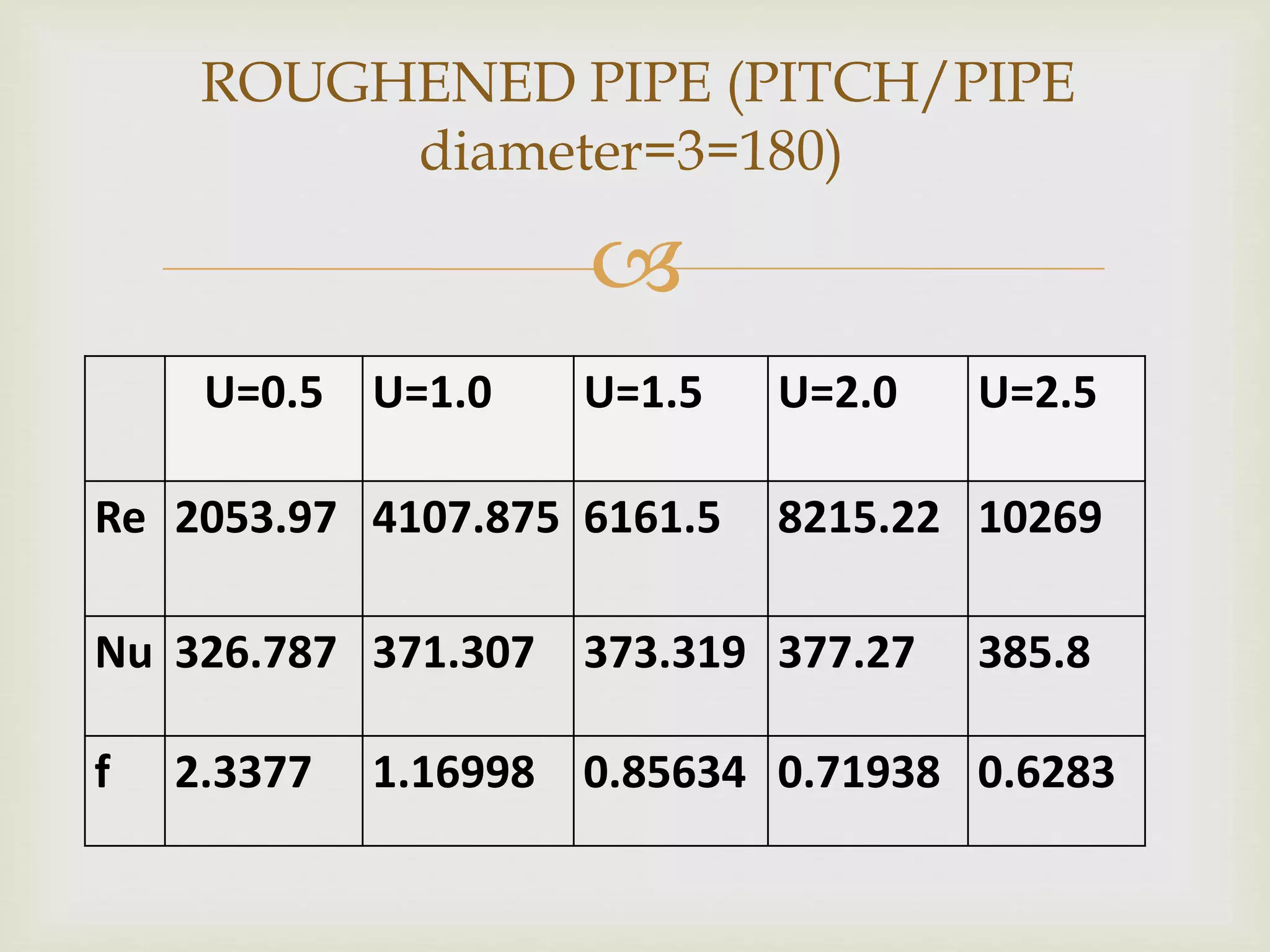
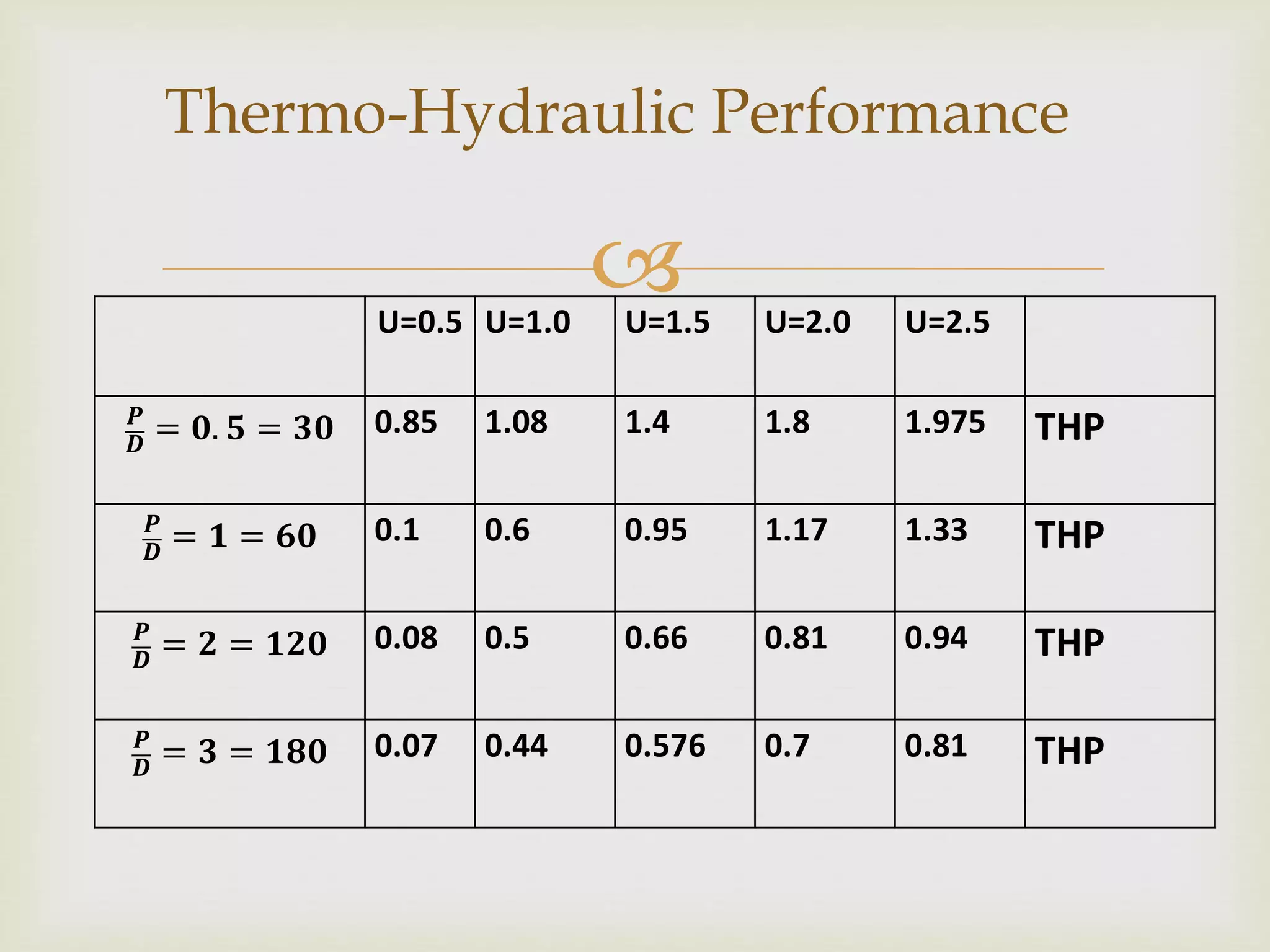
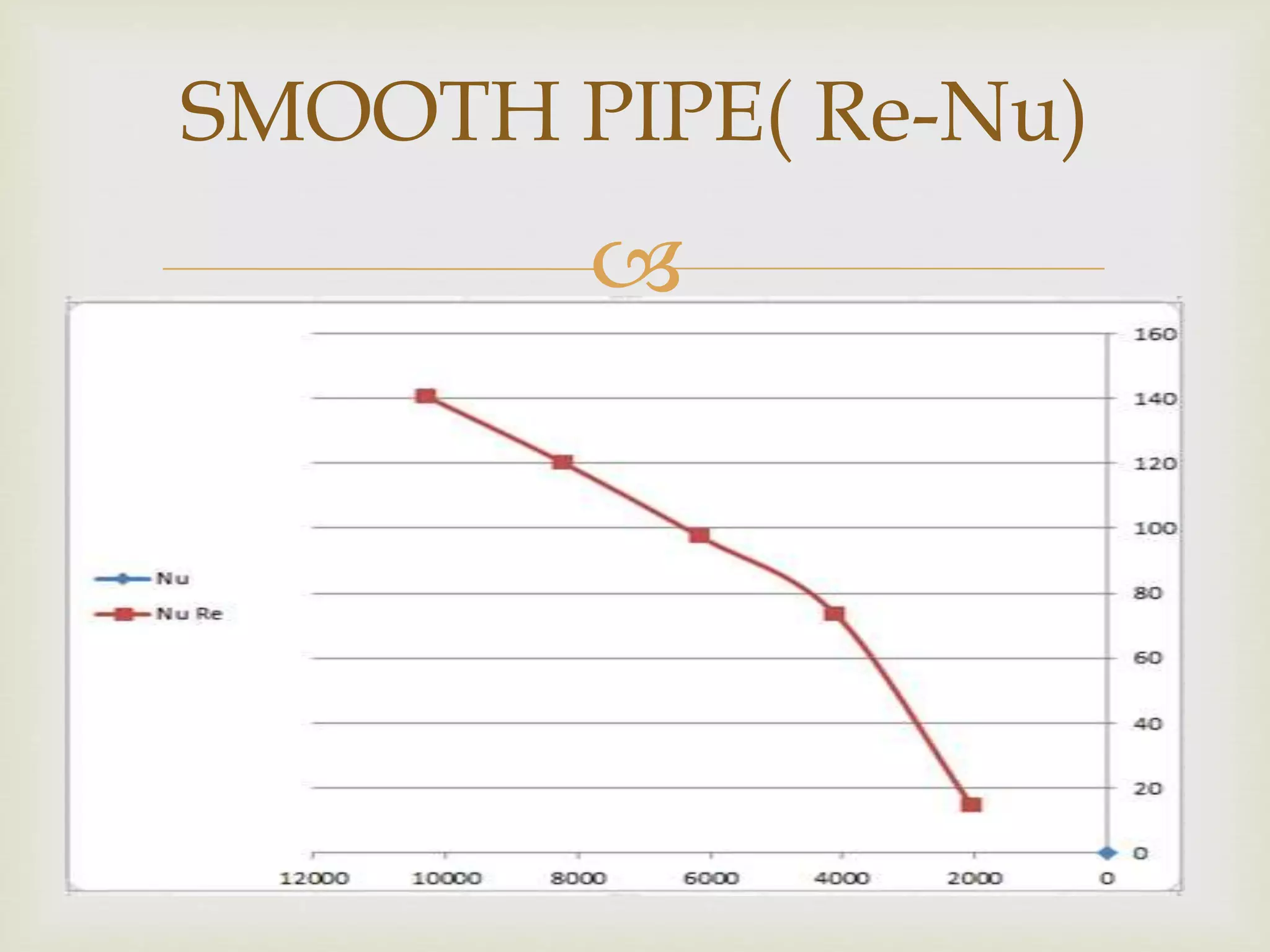
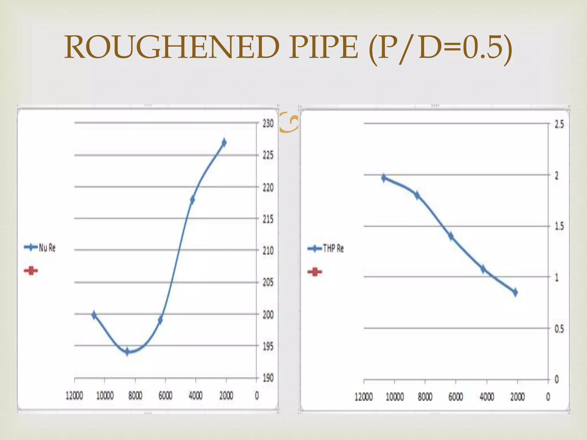
![[IJET-V2I3P20] Authors: Pravin S.Nikam , Prof. R.Y.Patil ,Prof. P.R.Patil , P...](https://cdn.slidesharecdn.com/ss_thumbnails/ijet-v2i3p20-160711112139-thumbnail.jpg?width=640&height=640&fit=bounds)


