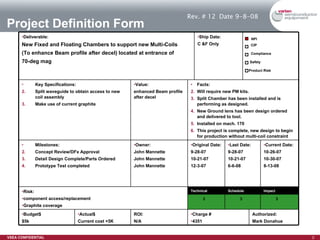
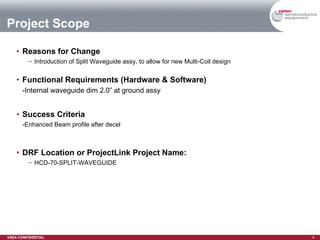
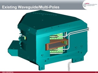
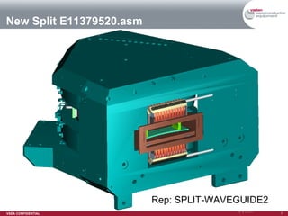
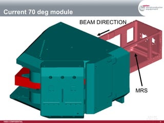
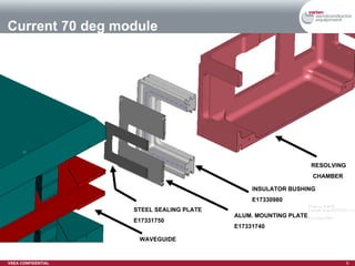
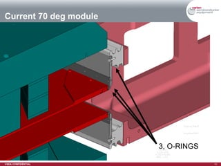
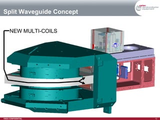
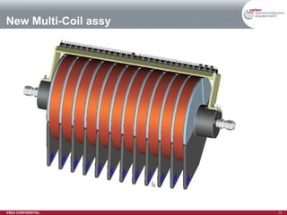
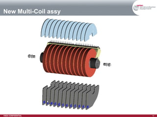
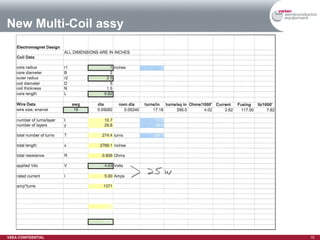
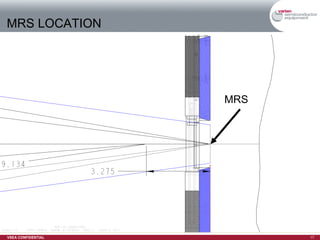
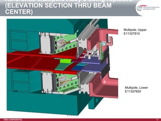
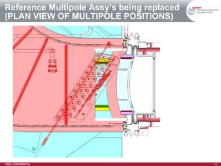
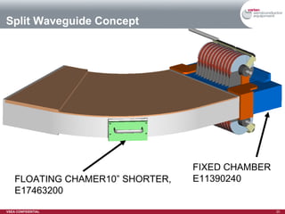
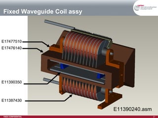
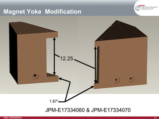
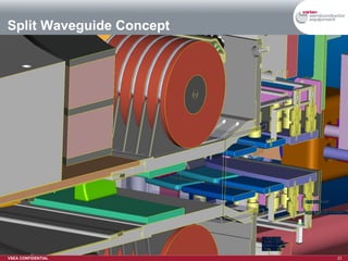
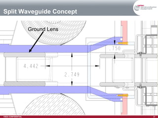
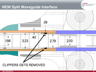
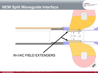
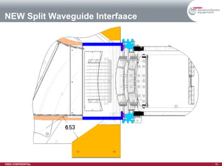
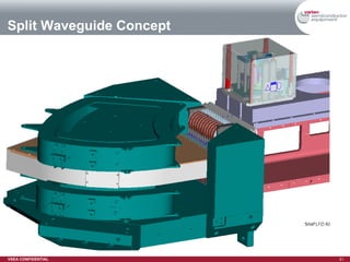
HCD-70-DEG SPLIT WAVEGUIDE Rev-12, 9-8-08 John Mannette Project Definition Form Revised:   3/21/07
Project Definition Form Rev. # 12 Date 9-8-08 Authorized: Mark Donahue Ship Date: C &F Only 3 3 3 Current Date: 10-26-07 10-30-07 8-13-08 Last Date: 9-28-07 10-21-07 6-6-08 Schedule Impact Original Date: 9-28-07 10-21-07 12-3-07 Owner: John Mannette John Mannette John Mannette Milestones: Concept Review/DFx Approval Detail Design Complete/Parts Ordered Prototype Test completed Charge # 4351 ROI: N/A Actual$ Current cost +5K Budget$ $5k Technical Risk:  component access/replacement  Graphite coverage Facts: Will require new PM kits. Split Chamber has been installed and is performing as designed. New Ground lens has been design ordered and delivered to tool. Installed on mach. 170 This project is complete, new design to begin for production without multi-coil constraint Value: enhanced Beam profile after decel Key Specifications: Split waveguide to obtain access to new coil assembly  Make use of current graphite NPI CIP Compliance Safety Product Risk Deliverable: New Fixed and Floating Chambers to support new Multi-Coils  (To enhance Beam profile after decel) located at entrance of 70-deg mag
History 5-20-08 –Split waveguide begins to be installed Waveguide found to have leak/repaired Pole gap to be increased to accept new coil-tips Reworked ground lens to match new D1 curve Reworked Waveguide to accept new coil-tips 5-23-08 –Split waveguide installation complete 5-28-08 –Testing in process Brought up 20k Argon. Turned on pole tip coils to 20A to look for effect on beam. Profile indicates beam is being squeezed. Tried to reverse the polarity but it has no effect. Looks the same whether in Plus or Minus mode. Opened up to check polarity switch and found there isn't one. * Ran 300ev Boron 2to1. Multicoil tuning is ineffective. The multicoils themselves will move the beam adequately, but the algorithm doesn't seem to work well. 6-11-08 –Testing in process -New Multi-Poles did not perform as intended, Proto-Type Multi-Poles made by Chris Alden will be installed  -New Shims for the Prototype Multi-Poles have been ordered and will arrive 6-11-08 -New Ground lens has been requested which will open the aperture by .375”
Reasons for Change Introduction of Split Waveguide assy, to allow for new Multi-Coil design  Functional Requirements (Hardware & Software) -Internal waveguide dim 2.0” at ground assy Success Criteria -Enhanced Beam profile after decel DRF Location or ProjectLink Project Name: HCD-70-SPLIT-WAVEGUIDE Project Scope
Technical Solution
Existing Waveguide/Multi-Poles
New Split E11379520.asm Rep: SPLIT-WAVEGUIDE2
Current 70 deg module MRS BEAM DIRECTION
Current 70 deg module WAVEGUIDE RESOLVING CHAMBER INSULATOR BUSHING E17330980 STEEL SEALING PLATE E17331750 ALUM. MOUNTING PLATE E17331740
Current 70 deg module 3, O-RINGS
Objectives Add Multi-Coil assembly with Field extending bars Add Ground Lens assembly Split The Waveguide assembly to gain access to Multi-Coils
Split Waveguide Concept NEW MULTI-COILS
New Multi-Coil assy
New Multi-Coil assy
New Multi-Coil assy
Relative positions Multipole/Multicoil field extenders (New position moved 2.5” downstream)
MRS LOCATION MRS
Reference Multipole Assy’s being replaced (ELEVATION SECTION THRU BEAM CENTER) Multipole, Upper E11327810 Multipole, Lower E11327820
Reference Multipole Assy’s being replaced  (PLAN VIEW OF MULTIPOLE POSITIONS)
Split Waveguide Concept FIXED CHAMBER E11390240 FLOATING CHAMER10” SHORTER, E17463200
Fixed Waveguide Coil assy E11390240.asm E17477510 E17476140 E11387430 E11390350
Magnet Yoke  Modification JPM-E17334060 & JPM-E17334070 1.87” 12.25
Split Waveguide Concept
Split Waveguide Concept Ground Lens
Split Waveguide Concept
Current Waveguide Entrance
New Waveguide Entrance
NEW Split Waveguide Interface CLIPPERS GETS REMOVED
NEW Split Waveguide Interface IN-VAC FIELD EXTENDERS
NEW Split Waveguide Interfaace
Split Waveguide Concept
Safety Requirements 70 deg Waveguide will be removable using the existing ergo-lift and end effectors
Test Plan & Results  Test plan to be defined
Reliability Goals (TO BE COMPLETED) Describe “Reliability Impact” Estimate of Higher/Lower Reliability and why Manufacturer data availability to support estimate? In house Reliability Test required?  Test plan and schedule? Consider using the following Quality tools to help determine Reliability Impact: Cause & Effect Diagrams FMEA 5-Why Method Scatter Diagrams Control Charts Process Maps If N/A – please give a quick explanation
Manufacturability (Delete if DFx is required on project) Describe plans, or discuss at Concept Review.  Must be completed for Final Design Review. Design for Manufacturability Describe Pok-e-Yoke design features. Identify QN’s resolved by the design. Describe harness & facilities routing paths. Describe minimized harnessing exposure and easy access features. Identify cable breakpoints and bulkheads between modules. Describe “plug-and-play” capability harnessing for all options/selects /specials. Describe use of VSEA common connectors/pins/parts/assemblies (commonality). Identify mechanical cable supports/brackets/retractors. Describe minimized parts removed from tool & cables disconnected at shipping. If N/A – please give a quick explanation
Serviceability  (Delete if DFx is required on project) Describe plans, or discuss at Concept Review.  Must be completed for Final Design Review. Design for Serviceability   Describe ability to access all serviceable areas with ease. Describe ability to slide out all controllers / supplies without disconnecting cables / harnesses. Describe ability to ergonomically remove heavy components. Define MTTR requirement. Describe the field replaceable Unit (FRU) strategy (reliability). Describe the life expectancy for replaceable parts. Identify the updated field documentation. If N/A – please give a quick explanation
Testability & Source-ability (Delete if DFx is required on project) Describe plans, or discuss at Concept Review.  Must be completed for Final Design Review. Design for Testability Describe self-teach and or self-test (including light links) features. Describe Auto-calibration and Auto-alignment features. Describe features that improve sub-system test (electrical or mechanical). If N/A – please give a quick explanation Design for Source-ability Describe the make/buy strategy. List items that are single sourced, why, and the risk to the project Describe how the documentation supports the High-Level Assembly (HLA) strategy (outsourcing). Describe the level of supplier testing. Describe how the supplier will be included in design for first build. If N/A – please give a quick explanation
Cost Targets (Delete if DFx is required on project) Describe “Product Cost Impact” Adding a level of complexity while attempting to cut cost by redesign of several components Anticipated cost up of $5k ($15,849.82+$5,000.00=$20,849.82)
Overall DFX Rating (Delete if DFx is not required on project) Please go to slide show and open this Link to open the DFX Scorecard Copy the Combined Scorecard into your PDF file. Rename the scorecard with the same file name as your PDF. Hyperlink the scorecard on this slide and delete this textbox. Combined Scorecard.xls
Other outstanding DFX Issues (lesson learned) (Delete if DFx is not required on project) Issues that may not have been captured by any scorecards
Technical Business Issues
Implementation Plan Required Tasks   (examples are items to consider, enter N/A if not required) Proliferation For example: feasibility, value benefit Upgrade: For example: all machines, only warranty machines, certain customers… Retrofit budget required Retrofit: For example: identify options or variations that need to be considered, Field Replacement Kit required? Replace on Failure: Field/Customers For example: driving change ahead of ECO cut-in,  (who, what, when, where, how) Forward Compliance: For example: Expected Cut In date or machine number, impact on inventory (scrap, rework, open orders, use up), parts requiring Material Hold form Cut-In Plan: Manufacturing
Implementation Plan  (continued) Required Tasks   (examples are items to consider, enter N/A if not required) Proliferation Do customers need to understand the proposed change? Product Change Notification: Other: Is field communication required? Product Support Bulletin: Communication
Intellectual Properties (IP) Are there any IP opportunities in this design, if so what is the status, i.e. has the disclosure/patent been filed? If N/A – please give a quick explanation
Program Issues
Schedule and Manpower Loading See SPS (pg-2)
Current Program Status Describe what has been accomplished to date and what the next steps to be completed in the Engineering Design Process will be.
Appendix A Signoff Sheet Action Items
Mandatory Sign Off for ECO submission Project : Product Line : Date of Review : Project Engineer : ECO Number : Email to Eng. owner from any member of the team, accepting the design, will pass as a signature. Email to be included with the PDF file. ** Required only if DFx is implemented on the Project Business Development DF(x) team** Reliability DF(x) team** Materials/Supply Chain DF(x) team** Service DF(x) team** Install DF(x) team** Cost DF(x) team** Materials* Manufacturing Engineering* Manufacturing DF(x) team** Safety* Systems/Product Eng. Manager* Comments Name Department
Non-Mandatory Sign Off Sheet Meeting Notes:   Physics Software Engineering Product Support Test Engineering Mechanical Engineering Tech Pubs Quality Electrical Engineering Finance Marketing Comments Name Department
Action Items (AI) 4.  3.  2.  6.  8.  7.  5.  1.  At next review, or before CCB, describe the resolution of each AI Identify who will resolve each AI Fill in with AIs identified during the review and an expect resolution date Resolution Owner Action

Hcd 70 Split Waveguide

  • 1.
    HCD-70-DEG SPLIT WAVEGUIDERev-12, 9-8-08 John Mannette Project Definition Form Revised: 3/21/07
  • 2.
    Project Definition FormRev. # 12 Date 9-8-08 Authorized: Mark Donahue Ship Date: C &F Only 3 3 3 Current Date: 10-26-07 10-30-07 8-13-08 Last Date: 9-28-07 10-21-07 6-6-08 Schedule Impact Original Date: 9-28-07 10-21-07 12-3-07 Owner: John Mannette John Mannette John Mannette Milestones: Concept Review/DFx Approval Detail Design Complete/Parts Ordered Prototype Test completed Charge # 4351 ROI: N/A Actual$ Current cost +5K Budget$ $5k Technical Risk: component access/replacement Graphite coverage Facts: Will require new PM kits. Split Chamber has been installed and is performing as designed. New Ground lens has been design ordered and delivered to tool. Installed on mach. 170 This project is complete, new design to begin for production without multi-coil constraint Value: enhanced Beam profile after decel Key Specifications: Split waveguide to obtain access to new coil assembly Make use of current graphite NPI CIP Compliance Safety Product Risk Deliverable: New Fixed and Floating Chambers to support new Multi-Coils (To enhance Beam profile after decel) located at entrance of 70-deg mag
  • 3.
    History 5-20-08 –Splitwaveguide begins to be installed Waveguide found to have leak/repaired Pole gap to be increased to accept new coil-tips Reworked ground lens to match new D1 curve Reworked Waveguide to accept new coil-tips 5-23-08 –Split waveguide installation complete 5-28-08 –Testing in process Brought up 20k Argon. Turned on pole tip coils to 20A to look for effect on beam. Profile indicates beam is being squeezed. Tried to reverse the polarity but it has no effect. Looks the same whether in Plus or Minus mode. Opened up to check polarity switch and found there isn't one. * Ran 300ev Boron 2to1. Multicoil tuning is ineffective. The multicoils themselves will move the beam adequately, but the algorithm doesn't seem to work well. 6-11-08 –Testing in process -New Multi-Poles did not perform as intended, Proto-Type Multi-Poles made by Chris Alden will be installed -New Shims for the Prototype Multi-Poles have been ordered and will arrive 6-11-08 -New Ground lens has been requested which will open the aperture by .375”
  • 4.
    Reasons for ChangeIntroduction of Split Waveguide assy, to allow for new Multi-Coil design Functional Requirements (Hardware & Software) -Internal waveguide dim 2.0” at ground assy Success Criteria -Enhanced Beam profile after decel DRF Location or ProjectLink Project Name: HCD-70-SPLIT-WAVEGUIDE Project Scope
  • 5.
  • 6.
  • 7.
    New Split E11379520.asmRep: SPLIT-WAVEGUIDE2
  • 8.
    Current 70 degmodule MRS BEAM DIRECTION
  • 9.
    Current 70 degmodule WAVEGUIDE RESOLVING CHAMBER INSULATOR BUSHING E17330980 STEEL SEALING PLATE E17331750 ALUM. MOUNTING PLATE E17331740
  • 10.
    Current 70 degmodule 3, O-RINGS
  • 11.
    Objectives Add Multi-Coilassembly with Field extending bars Add Ground Lens assembly Split The Waveguide assembly to gain access to Multi-Coils
  • 12.
    Split Waveguide ConceptNEW MULTI-COILS
  • 13.
  • 14.
  • 15.
  • 16.
    Relative positions Multipole/Multicoilfield extenders (New position moved 2.5” downstream)
  • 17.
  • 18.
    Reference Multipole Assy’sbeing replaced (ELEVATION SECTION THRU BEAM CENTER) Multipole, Upper E11327810 Multipole, Lower E11327820
  • 19.
    Reference Multipole Assy’sbeing replaced (PLAN VIEW OF MULTIPOLE POSITIONS)
  • 20.
    Split Waveguide ConceptFIXED CHAMBER E11390240 FLOATING CHAMER10” SHORTER, E17463200
  • 21.
    Fixed Waveguide Coilassy E11390240.asm E17477510 E17476140 E11387430 E11390350
  • 22.
    Magnet Yoke Modification JPM-E17334060 & JPM-E17334070 1.87” 12.25
  • 23.
  • 24.
  • 25.
  • 26.
  • 27.
  • 28.
    NEW Split WaveguideInterface CLIPPERS GETS REMOVED
  • 29.
    NEW Split WaveguideInterface IN-VAC FIELD EXTENDERS
  • 30.
  • 31.
  • 32.
    Safety Requirements 70deg Waveguide will be removable using the existing ergo-lift and end effectors
  • 33.
    Test Plan &Results Test plan to be defined
  • 34.
    Reliability Goals (TOBE COMPLETED) Describe “Reliability Impact” Estimate of Higher/Lower Reliability and why Manufacturer data availability to support estimate? In house Reliability Test required? Test plan and schedule? Consider using the following Quality tools to help determine Reliability Impact: Cause & Effect Diagrams FMEA 5-Why Method Scatter Diagrams Control Charts Process Maps If N/A – please give a quick explanation
  • 35.
    Manufacturability (Delete ifDFx is required on project) Describe plans, or discuss at Concept Review. Must be completed for Final Design Review. Design for Manufacturability Describe Pok-e-Yoke design features. Identify QN’s resolved by the design. Describe harness & facilities routing paths. Describe minimized harnessing exposure and easy access features. Identify cable breakpoints and bulkheads between modules. Describe “plug-and-play” capability harnessing for all options/selects /specials. Describe use of VSEA common connectors/pins/parts/assemblies (commonality). Identify mechanical cable supports/brackets/retractors. Describe minimized parts removed from tool & cables disconnected at shipping. If N/A – please give a quick explanation
  • 36.
    Serviceability (Deleteif DFx is required on project) Describe plans, or discuss at Concept Review. Must be completed for Final Design Review. Design for Serviceability Describe ability to access all serviceable areas with ease. Describe ability to slide out all controllers / supplies without disconnecting cables / harnesses. Describe ability to ergonomically remove heavy components. Define MTTR requirement. Describe the field replaceable Unit (FRU) strategy (reliability). Describe the life expectancy for replaceable parts. Identify the updated field documentation. If N/A – please give a quick explanation
  • 37.
    Testability & Source-ability(Delete if DFx is required on project) Describe plans, or discuss at Concept Review. Must be completed for Final Design Review. Design for Testability Describe self-teach and or self-test (including light links) features. Describe Auto-calibration and Auto-alignment features. Describe features that improve sub-system test (electrical or mechanical). If N/A – please give a quick explanation Design for Source-ability Describe the make/buy strategy. List items that are single sourced, why, and the risk to the project Describe how the documentation supports the High-Level Assembly (HLA) strategy (outsourcing). Describe the level of supplier testing. Describe how the supplier will be included in design for first build. If N/A – please give a quick explanation
  • 38.
    Cost Targets (Deleteif DFx is required on project) Describe “Product Cost Impact” Adding a level of complexity while attempting to cut cost by redesign of several components Anticipated cost up of $5k ($15,849.82+$5,000.00=$20,849.82)
  • 39.
    Overall DFX Rating(Delete if DFx is not required on project) Please go to slide show and open this Link to open the DFX Scorecard Copy the Combined Scorecard into your PDF file. Rename the scorecard with the same file name as your PDF. Hyperlink the scorecard on this slide and delete this textbox. Combined Scorecard.xls
  • 40.
    Other outstanding DFXIssues (lesson learned) (Delete if DFx is not required on project) Issues that may not have been captured by any scorecards
  • 41.
  • 42.
    Implementation Plan RequiredTasks (examples are items to consider, enter N/A if not required) Proliferation For example: feasibility, value benefit Upgrade: For example: all machines, only warranty machines, certain customers… Retrofit budget required Retrofit: For example: identify options or variations that need to be considered, Field Replacement Kit required? Replace on Failure: Field/Customers For example: driving change ahead of ECO cut-in, (who, what, when, where, how) Forward Compliance: For example: Expected Cut In date or machine number, impact on inventory (scrap, rework, open orders, use up), parts requiring Material Hold form Cut-In Plan: Manufacturing
  • 43.
    Implementation Plan (continued) Required Tasks (examples are items to consider, enter N/A if not required) Proliferation Do customers need to understand the proposed change? Product Change Notification: Other: Is field communication required? Product Support Bulletin: Communication
  • 44.
    Intellectual Properties (IP)Are there any IP opportunities in this design, if so what is the status, i.e. has the disclosure/patent been filed? If N/A – please give a quick explanation
  • 45.
  • 46.
    Schedule and ManpowerLoading See SPS (pg-2)
  • 47.
    Current Program StatusDescribe what has been accomplished to date and what the next steps to be completed in the Engineering Design Process will be.
  • 48.
    Appendix A SignoffSheet Action Items
  • 49.
    Mandatory Sign Offfor ECO submission Project : Product Line : Date of Review : Project Engineer : ECO Number : Email to Eng. owner from any member of the team, accepting the design, will pass as a signature. Email to be included with the PDF file. ** Required only if DFx is implemented on the Project Business Development DF(x) team** Reliability DF(x) team** Materials/Supply Chain DF(x) team** Service DF(x) team** Install DF(x) team** Cost DF(x) team** Materials* Manufacturing Engineering* Manufacturing DF(x) team** Safety* Systems/Product Eng. Manager* Comments Name Department
  • 50.
    Non-Mandatory Sign OffSheet Meeting Notes: Physics Software Engineering Product Support Test Engineering Mechanical Engineering Tech Pubs Quality Electrical Engineering Finance Marketing Comments Name Department
  • 51.
    Action Items (AI)4. 3. 2. 6. 8. 7. 5. 1. At next review, or before CCB, describe the resolution of each AI Identify who will resolve each AI Fill in with AIs identified during the review and an expect resolution date Resolution Owner Action