Download to read offline


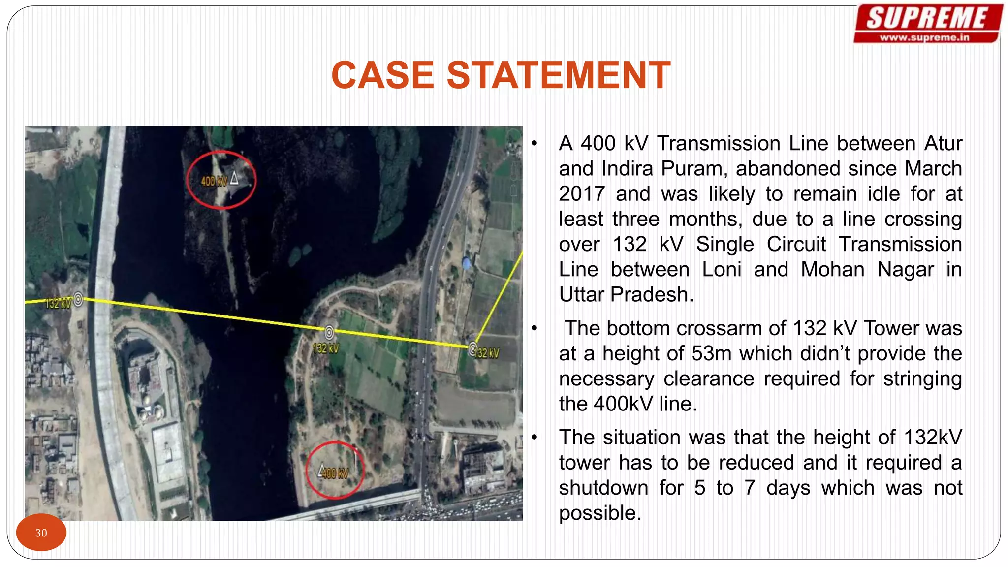


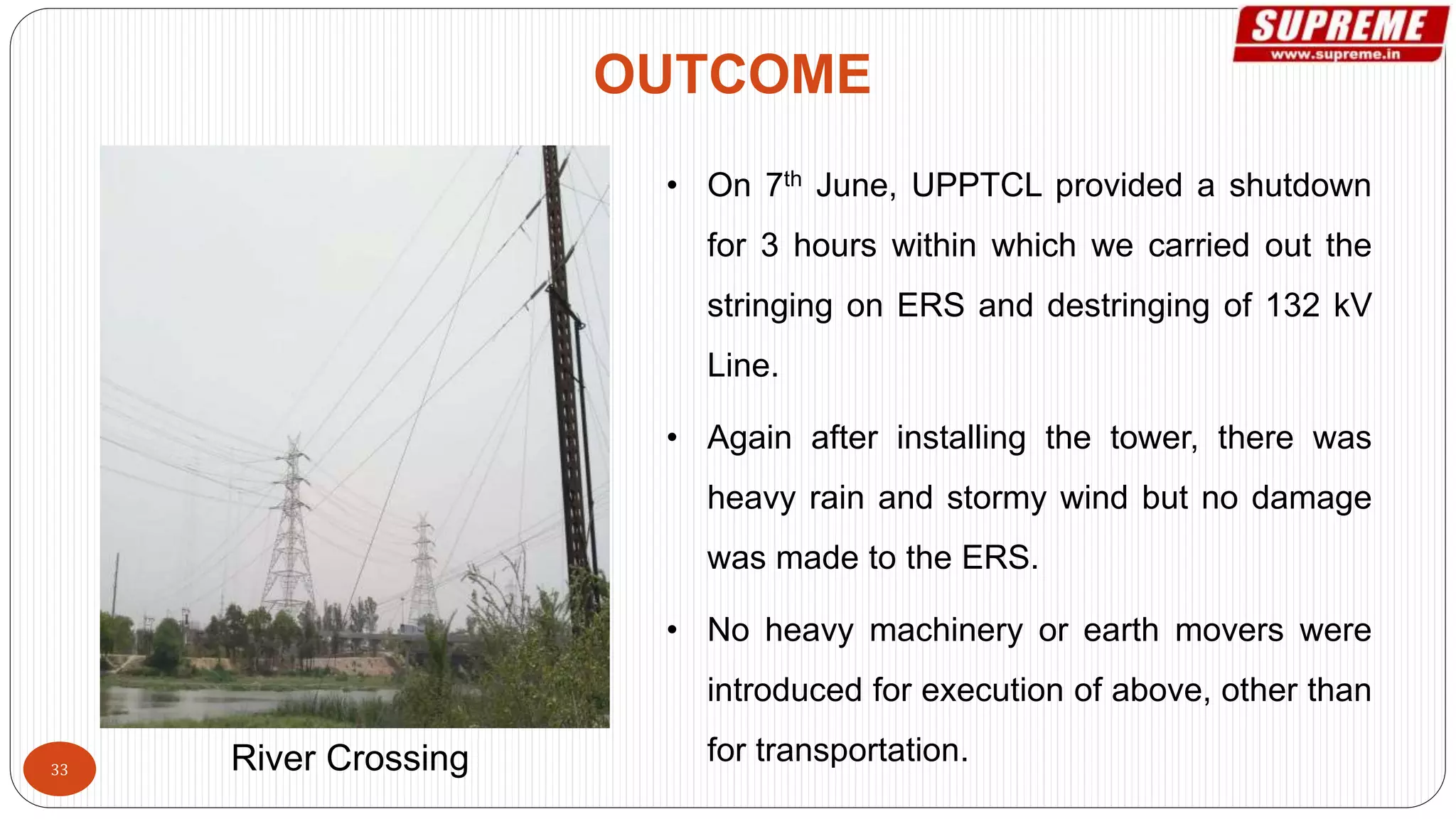


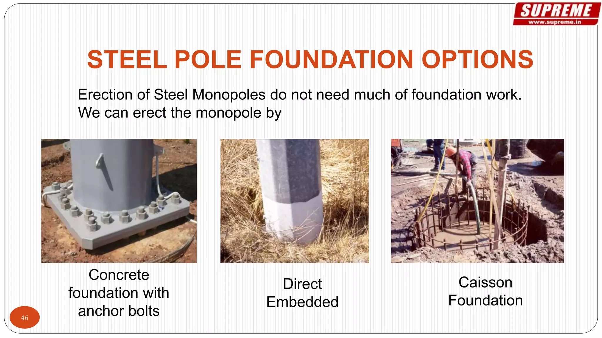


The document discusses Supreme & Co.'s manufacturing capabilities and products related to transmission line infrastructure. It summarizes their monopole design and manufacturing process, provides comparisons to lattice structures, and outlines specifications, testing, and approvals. Case studies demonstrate the use of emergency restoration towers for transmission line projects in India.


