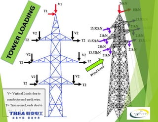
400KV DOUBLE CIRCUIT CHALINZE – MKURANGA
VIA KINYEREZI TRANSMISSION LINE
TOWER DESIGN METHODOLOGY AND
PHILOSOPHY
30/MAY/2024
INTRODUCTION
 The works covered by these technical specifications and the Employer’s requirements
form part of the 400kV Chalinze – Mkuranga Via Kinyerezi transmission line project.
 The project consists construction of 136 km long, 400 kV double circuit triple bundle
AAAC SORBUS conductor transmission line (400kV transmission line using 3 SORBUS
conductor per phase (AAAC – 61/3.71 wires)), using one (1) OPGW with capacity for 48
optical fibers and one (1) Overhead Ground Wire (ACSR - 95/55 with Inner Core Aluminium
Clad Steel) strung on lattice steel towers from New 400kV Chalinze substation to New
Mkuranga substation via Kinyerezi substation in Dar es Salaam City.
 The project consists of engineering design, procurement, manufacturing, inspection, site
delivery & storage, construction & erection, start-up field tests, system testing, and work
related for the commissioning of the 400 kV transmission line, including all temporary
works.
GIST
1. Over View
2. Tower Nomenclature
3. Tower Components
4. Tower Anatomy
5. Employer’s Requirements
6. Design Concepts
7. Tower Loading
8. Standards For Loading
9. Analysis & Design_PLS Tower
Towers constitute vital component of
a very
as they perform the important
transmission lines
function of supporting the power conductors and
overhead ground wires at the required distances
above the ground level maintaining the appropriate
inter-conductor spacing within permissible limits
under all operating conditions.
Transmission line towers are used to transmit
electricity from power generation station to utilities
/Sub-stations.
Over View
Tower Nomenclature
Sr.
No.
TOWER DESIGNATIONS DEVIATION
1
NS (NormalSuspension)tower
0-20
2
LA (Light Angle) tower –At angle
points / Used as a Section Tower
0-150
3
MA (MediumAngle) Tower- At
angle points / used as a
Transposition
15°-30°
4
HA (Heavy Angle)
30°-70°
5
DE (Dead End/ Terminal Tower)
0°-90°
6 TP (Transposition) Tower 0°-20
Tower Components
Tower Anatomy
Design Requirements (Employer
Requirements)
 Voltage Requirements/System
System highest voltage for equipment
/power frequency - (420 / 50 kV/Hz ).
Nominal voltage (400 kV).
 Conductors.
• Phase conductor (AAC-SORBUS)
• Earth wire (ACSR 95/55)
• OPGW (similar to AL/ACS 95/55)
 Design Wind Speed
• 39m/s (3s gust)
 Design Temperatures
• Maximum ambient temperature (+40
°C)
• Conductor temperature (+10 - +80
°C)
• Everyday temperature (+27 °C)
 Line Data
• Number of circuits (2)
• Number of conductors per phase (3)
• Number of OPGW (1)
• Number of OHGW (1)
• Total approximate length of lines
(136 km)
 Minimum Partial factors for load actions
• For permanent actions (1.2)
• For variable actions(1.3)
• For construction and maintenance
loads(1.5)
 Minimum Partial factors for material
strength.
• Structural steel sections, plates, etc.
for towers (1.25)
• Bolts(1.25)
• Concrete(1.5)
Design Requirements (Employer
Requirements) cont’d
 Maximum slenderness Ratios (L/r) to
EN50341-1-J
• Main leg, stub, and main compression
members in cross-arm (120).
• All other members having computed
stresses (200).
• Redundant members without
computed stresses (250).
• Tension members only (300).
 Minimum thickness (t) and size of steel
members of towers.
• Main leg, stub, and main compression
members in cross-arm (≥ 6mm).
• All other members having computed
stresses (≥ 5mm).
• Redundant members without
computed stresses (≥ 5mm).
• Gusset plates (≥ 6mm).
• Minimum angle bars: equal angle sections
(L45x45xt).
 Minimum Partial factors for load actions
• For permanent actions (1.2)
• For variable actions(1.3)
• For construction and maintenance
loads(1.5)
 Insulators.
 Insulator Type for Suspension string Cap and
Pin.
• IEC designation (U210BS, IEC 60305).
 Insulator Type for Tension string Cap and Pin
• IEC designation (U210B, IEC 60305).
Sag Tension Configuration Clearances
Design Concepts
1. Sag – Tension Calculation
2. Fixing configuration by providing
minimum required clearances
3. Loading Calculation.
4. Loading Combination.
5. Analysis & Design
6. Detailing
7. Prototype testing of towers
Tower Configuration
Clearances considered while design of Tower
 Ground Clearance
 Live Metal Clearance
 Mid Span Clearance
 Shielding Angle
 Clearances.
 Minimum clearance between phase
conductors Dpp (4.2 m)
 Minimum clearance to earthed parts Del
(3.3m)
 Minimum Vertical Clearances
• Normal ground (10.00m)
• Roads and streets (12.00m)
• Rivers (no ships) (11.00m)
 Minimum Horizontal Clearance.
• Highway and Main roads (30m)
• Energy Pipeline (30m)
• Towers are analyzed for loads applied in all three directions namely Transverse ( FX ),
Vertical ( FY) and Longitudinal (FZ) direction of the line.
• Transverse loads consists of – ( Loads acting perpendicular to TL LINE )
 Wind on Conductor
 Wind on Insulator
 Component of Wire Tension in Transverse Direction (Deviation Load)
 Wind on Tower Body
• Vertical Load consists of –
 Weight of Wire
 Weight of Insulator
 Weight of Line man & Tools
 Self Weight of Tower
• Longitudinal Load Consist of – ( Loads acting parallel to TL LINE )
 Component of Unbalanced pull of the wire in the longitudinal
direction.
Loading
Calculations:
Type of loading conditions
 Reliability Condition
- Maximum design load experience by the tower
 Security condition
- Accidental loading due to broken wire condition
 Safety Condition.
- Erection and Maintenance loading condition
Loading Calculations:
Reliability Condition
Transverse Load :
 Wind Load on Conductor/Earthwire
 Wind Load on Insulator
 Mechanical Tension of Conductor/Earth wire due to deviation
 Wind Load on Tower Body
Loading Calculations:
Vertical Load :
 Self weight of Structure.
 Weight of Conductor and Earth wire
 Weight of Insulators and other Accessories
 Ice load in case ice effect.
Longitudinal Load :
 Wind load on Structure in case of Oblique wind condition.
 Wind load on Insulator in case of Oblique wind for Suspension towers.
 Mechanical tensions in Longitudinal directions in case of Dead End
Terminal Towers.
Loading Calculations:
Reliability Condition
Security Condition
Loading Calculations:
Transverse Load :
 Wind Load on Conductor/Earth wire
 Wind Load on Insulator
 Mechanical Tension of Conductor/Earth wire due to deviation(intact
condition)
 Wind Load on Tower Body
Vertical Load :
 Self weight of Structure.
 Weight of Conductor and Earth wire
 Weight of Insulators and other Accessories
 Ice load in case ice effect.
Longitudinal Load :
 Wind load on Structure in case of Oblique wind condition.
 Wind load on Insulator in case of Oblique wind for Suspension towers.
 Mechanical tensions due to failure in Longitudinal directions.
Loading Calculations:
Security Condition
Loading Calculations:
Safety Condition
Transverse Load :
 Mechanical Tension of Conductor/Earth wire due to deviation
Vertical Load :
 Self weight of Structure.
 Weight of Conductor and Earth wire
 Weight of Insulators and other Accessories
 Weight of Line man with tools
 Additional loads due stay wires uses during stringing time.
Longitudinal Load :
 Mechanical tensions due to stay wires uses in stringing time.
Standards for Load Calculation
Loads are calculated as per the guide lines furnished in
specification/standard
•Standards for Calculation of Loads
 EN 50341
 ASCE-10
 IEC – 826
•The loads are calculated for following Conditions
 Reliability / Working condition
 Security / Broken wire condition
 Safety / Erection & maintenance Condition
ANALYSIS & DESIGN_PLS TOWER
MODELING
IN
PLS
TOWE
R
GENERA
L DATA
PRIMARY
JOINTS
secondary
JOINTS
ADD
GROUPS
MEMBER
ADDITION
GRUPING
MEMBERS
BRIEF & FLOW CHAT
• Tower is idealized as 3-D space structure and analysis is carried out by finite element
software PLS Tower
• The critical compression and tension in each member group is found out
• Required FOS is provided in input file to find out ultimate force
• Members and Connections are designed for these forces
• Several iterations are carried to find out the optimum weight of tower
• The design out put is indicated in a drawing called Basic Tower Configuration &
Electrical Clearance Diagram
GENERAL DATA
GENERAL DATA DESIGN CHECK DESIGN CHECK OPTIONS
Note: All the details in the general data need to be filled in accordance to the project requirements
PRIMARY JOINTS AND
SECONDARY JOINTS
A tower model isbuilt by inserting angle or round members between joints and connecting
other components to existing joints. There are key joints which must be located by their
coordinates (Primary joints), other joints that are located by straight line interpolation or
extrapolation between key joints (Secondary joints).
PRIMARY JOINTS AND SECONDARY JOINTS
•Create a joint label
•Add the symmetry of the joint
•Enter the co ordinates of the
joint , mentioning in X,Y,Z in
accordance to the PLs co-
ordinate system
•Enter the displacement
restraint and rotation restraint
if applicable or else it can be
declared Free
PRIMARY JOINTS
•After the primary joint is
created , a secondary joint
can be Added between 2
Primary joints
•A secondary joint can also be
added by providing ratio of
member length at which it
should be added after the
members have been created
SECONDARY JOINTS
GROUPING
 In the grouping table , We have to add the Group labels
and the group description
according to the requirement in modeling . These should
be such that it could define the members assigned to the
respective group
 Then we have to provide the Angle type and size for the
respective group
 Assign the Element type and also the group type
 Using the Geometry / Groups , we can
• Find the information of any group ,
• Find the members of respective group
• Modify any group type
• Modify any element type
• Rename any group
• Delete any unused groups
MEMBER ADD
 In the member table , We have to add the member labels and the group label
according to the groups defined for each member type .
 The member symmetry needs to be entered.
 The origin joint and the end joint between which the member needs to be added
has to be entered .
 The eccentricity code , Restraint code and ratios of RLX , RL
Yand RLZneeds to be
entered according to the requirement
 Bolt type i.e. diameter of bolt used needs to be entered according to the technical
specifications .
 No. of bolts and no. of shear planes needs to be added in accordance to the
member angle and design requirement .
LOAD FILE
 Loads can be inputted in two ways
• Vector loads(LCA file) : In this the LCA
file is created and each individual
case loads is inputted one by one.
Batch import : In this the loads of all
the cases are given all at a time in
point loads column . In this the load
cases and loads with joint label will be
given as an input .
 Loading tree report : A report is
generated with all the loads imported .
 Remove LCA/LIC/EIA file references :
This is used to remove all the
references , so that we can freshly
import any loading without any stance
of previous loading left .
DESIGN
•After the model is generated
and loads have been
inputted , The model is
checked using Model/Check.
•Then once the check is
successful with 0 errors , The
model is run using Model/Run.
•This will generate a Deformed
geometry
RUN
ANALYSIS
•After the model is run
successfully then it is
analyzed using
Model/Generate Analysis
results report
•Then an Analysis report will be
generated. Then you have to
design section as per the
requirement given in
specification .
ThankYOU

TOWER DESIGN PROCEDURE TOWER DESIGN BASIS .pptx

  • 1.
    400KV DOUBLE CIRCUITCHALINZE – MKURANGA VIA KINYEREZI TRANSMISSION LINE TOWER DESIGN METHODOLOGY AND PHILOSOPHY 30/MAY/2024
  • 2.
    INTRODUCTION  The workscovered by these technical specifications and the Employer’s requirements form part of the 400kV Chalinze – Mkuranga Via Kinyerezi transmission line project.  The project consists construction of 136 km long, 400 kV double circuit triple bundle AAAC SORBUS conductor transmission line (400kV transmission line using 3 SORBUS conductor per phase (AAAC – 61/3.71 wires)), using one (1) OPGW with capacity for 48 optical fibers and one (1) Overhead Ground Wire (ACSR - 95/55 with Inner Core Aluminium Clad Steel) strung on lattice steel towers from New 400kV Chalinze substation to New Mkuranga substation via Kinyerezi substation in Dar es Salaam City.  The project consists of engineering design, procurement, manufacturing, inspection, site delivery & storage, construction & erection, start-up field tests, system testing, and work related for the commissioning of the 400 kV transmission line, including all temporary works.
  • 3.
    GIST 1. Over View 2.Tower Nomenclature 3. Tower Components 4. Tower Anatomy 5. Employer’s Requirements 6. Design Concepts 7. Tower Loading 8. Standards For Loading 9. Analysis & Design_PLS Tower
  • 4.
    Towers constitute vitalcomponent of a very as they perform the important transmission lines function of supporting the power conductors and overhead ground wires at the required distances above the ground level maintaining the appropriate inter-conductor spacing within permissible limits under all operating conditions. Transmission line towers are used to transmit electricity from power generation station to utilities /Sub-stations. Over View
  • 5.
    Tower Nomenclature Sr. No. TOWER DESIGNATIONSDEVIATION 1 NS (NormalSuspension)tower 0-20 2 LA (Light Angle) tower –At angle points / Used as a Section Tower 0-150 3 MA (MediumAngle) Tower- At angle points / used as a Transposition 15°-30° 4 HA (Heavy Angle) 30°-70° 5 DE (Dead End/ Terminal Tower) 0°-90° 6 TP (Transposition) Tower 0°-20
  • 6.
  • 7.
  • 8.
    Design Requirements (Employer Requirements) Voltage Requirements/System System highest voltage for equipment /power frequency - (420 / 50 kV/Hz ). Nominal voltage (400 kV).  Conductors. • Phase conductor (AAC-SORBUS) • Earth wire (ACSR 95/55) • OPGW (similar to AL/ACS 95/55)  Design Wind Speed • 39m/s (3s gust)  Design Temperatures • Maximum ambient temperature (+40 °C) • Conductor temperature (+10 - +80 °C) • Everyday temperature (+27 °C)  Line Data • Number of circuits (2) • Number of conductors per phase (3) • Number of OPGW (1) • Number of OHGW (1) • Total approximate length of lines (136 km)  Minimum Partial factors for load actions • For permanent actions (1.2) • For variable actions(1.3) • For construction and maintenance loads(1.5)  Minimum Partial factors for material strength. • Structural steel sections, plates, etc. for towers (1.25) • Bolts(1.25) • Concrete(1.5)
  • 9.
    Design Requirements (Employer Requirements)cont’d  Maximum slenderness Ratios (L/r) to EN50341-1-J • Main leg, stub, and main compression members in cross-arm (120). • All other members having computed stresses (200). • Redundant members without computed stresses (250). • Tension members only (300).  Minimum thickness (t) and size of steel members of towers. • Main leg, stub, and main compression members in cross-arm (≥ 6mm). • All other members having computed stresses (≥ 5mm). • Redundant members without computed stresses (≥ 5mm). • Gusset plates (≥ 6mm). • Minimum angle bars: equal angle sections (L45x45xt).  Minimum Partial factors for load actions • For permanent actions (1.2) • For variable actions(1.3) • For construction and maintenance loads(1.5)  Insulators.  Insulator Type for Suspension string Cap and Pin. • IEC designation (U210BS, IEC 60305).  Insulator Type for Tension string Cap and Pin • IEC designation (U210B, IEC 60305).
  • 10.
    Sag Tension ConfigurationClearances Design Concepts 1. Sag – Tension Calculation 2. Fixing configuration by providing minimum required clearances 3. Loading Calculation. 4. Loading Combination. 5. Analysis & Design 6. Detailing 7. Prototype testing of towers
  • 11.
    Tower Configuration Clearances consideredwhile design of Tower  Ground Clearance  Live Metal Clearance  Mid Span Clearance  Shielding Angle  Clearances.  Minimum clearance between phase conductors Dpp (4.2 m)  Minimum clearance to earthed parts Del (3.3m)  Minimum Vertical Clearances • Normal ground (10.00m) • Roads and streets (12.00m) • Rivers (no ships) (11.00m)  Minimum Horizontal Clearance. • Highway and Main roads (30m) • Energy Pipeline (30m)
  • 13.
    • Towers areanalyzed for loads applied in all three directions namely Transverse ( FX ), Vertical ( FY) and Longitudinal (FZ) direction of the line. • Transverse loads consists of – ( Loads acting perpendicular to TL LINE )  Wind on Conductor  Wind on Insulator  Component of Wire Tension in Transverse Direction (Deviation Load)  Wind on Tower Body • Vertical Load consists of –  Weight of Wire  Weight of Insulator  Weight of Line man & Tools  Self Weight of Tower • Longitudinal Load Consist of – ( Loads acting parallel to TL LINE )  Component of Unbalanced pull of the wire in the longitudinal direction. Loading Calculations:
  • 14.
    Type of loadingconditions  Reliability Condition - Maximum design load experience by the tower  Security condition - Accidental loading due to broken wire condition  Safety Condition. - Erection and Maintenance loading condition Loading Calculations:
  • 15.
    Reliability Condition Transverse Load:  Wind Load on Conductor/Earthwire  Wind Load on Insulator  Mechanical Tension of Conductor/Earth wire due to deviation  Wind Load on Tower Body Loading Calculations:
  • 16.
    Vertical Load : Self weight of Structure.  Weight of Conductor and Earth wire  Weight of Insulators and other Accessories  Ice load in case ice effect. Longitudinal Load :  Wind load on Structure in case of Oblique wind condition.  Wind load on Insulator in case of Oblique wind for Suspension towers.  Mechanical tensions in Longitudinal directions in case of Dead End Terminal Towers. Loading Calculations: Reliability Condition
  • 17.
    Security Condition Loading Calculations: TransverseLoad :  Wind Load on Conductor/Earth wire  Wind Load on Insulator  Mechanical Tension of Conductor/Earth wire due to deviation(intact condition)  Wind Load on Tower Body
  • 18.
    Vertical Load : Self weight of Structure.  Weight of Conductor and Earth wire  Weight of Insulators and other Accessories  Ice load in case ice effect. Longitudinal Load :  Wind load on Structure in case of Oblique wind condition.  Wind load on Insulator in case of Oblique wind for Suspension towers.  Mechanical tensions due to failure in Longitudinal directions. Loading Calculations: Security Condition
  • 19.
    Loading Calculations: Safety Condition TransverseLoad :  Mechanical Tension of Conductor/Earth wire due to deviation Vertical Load :  Self weight of Structure.  Weight of Conductor and Earth wire  Weight of Insulators and other Accessories  Weight of Line man with tools  Additional loads due stay wires uses during stringing time. Longitudinal Load :  Mechanical tensions due to stay wires uses in stringing time.
  • 20.
    Standards for LoadCalculation Loads are calculated as per the guide lines furnished in specification/standard •Standards for Calculation of Loads  EN 50341  ASCE-10  IEC – 826 •The loads are calculated for following Conditions  Reliability / Working condition  Security / Broken wire condition  Safety / Erection & maintenance Condition
  • 21.
  • 22.
    MODELING IN PLS TOWE R GENERA L DATA PRIMARY JOINTS secondary JOINTS ADD GROUPS MEMBER ADDITION GRUPING MEMBERS BRIEF &FLOW CHAT • Tower is idealized as 3-D space structure and analysis is carried out by finite element software PLS Tower • The critical compression and tension in each member group is found out • Required FOS is provided in input file to find out ultimate force • Members and Connections are designed for these forces • Several iterations are carried to find out the optimum weight of tower • The design out put is indicated in a drawing called Basic Tower Configuration & Electrical Clearance Diagram
  • 23.
    GENERAL DATA GENERAL DATADESIGN CHECK DESIGN CHECK OPTIONS Note: All the details in the general data need to be filled in accordance to the project requirements
  • 24.
    PRIMARY JOINTS AND SECONDARYJOINTS A tower model isbuilt by inserting angle or round members between joints and connecting other components to existing joints. There are key joints which must be located by their coordinates (Primary joints), other joints that are located by straight line interpolation or extrapolation between key joints (Secondary joints).
  • 25.
    PRIMARY JOINTS ANDSECONDARY JOINTS •Create a joint label •Add the symmetry of the joint •Enter the co ordinates of the joint , mentioning in X,Y,Z in accordance to the PLs co- ordinate system •Enter the displacement restraint and rotation restraint if applicable or else it can be declared Free PRIMARY JOINTS •After the primary joint is created , a secondary joint can be Added between 2 Primary joints •A secondary joint can also be added by providing ratio of member length at which it should be added after the members have been created SECONDARY JOINTS
  • 26.
    GROUPING  In thegrouping table , We have to add the Group labels and the group description according to the requirement in modeling . These should be such that it could define the members assigned to the respective group  Then we have to provide the Angle type and size for the respective group  Assign the Element type and also the group type  Using the Geometry / Groups , we can • Find the information of any group , • Find the members of respective group • Modify any group type • Modify any element type • Rename any group • Delete any unused groups
  • 27.
    MEMBER ADD  Inthe member table , We have to add the member labels and the group label according to the groups defined for each member type .  The member symmetry needs to be entered.  The origin joint and the end joint between which the member needs to be added has to be entered .  The eccentricity code , Restraint code and ratios of RLX , RL Yand RLZneeds to be entered according to the requirement  Bolt type i.e. diameter of bolt used needs to be entered according to the technical specifications .  No. of bolts and no. of shear planes needs to be added in accordance to the member angle and design requirement .
  • 28.
    LOAD FILE  Loadscan be inputted in two ways • Vector loads(LCA file) : In this the LCA file is created and each individual case loads is inputted one by one. Batch import : In this the loads of all the cases are given all at a time in point loads column . In this the load cases and loads with joint label will be given as an input .  Loading tree report : A report is generated with all the loads imported .  Remove LCA/LIC/EIA file references : This is used to remove all the references , so that we can freshly import any loading without any stance of previous loading left .
  • 29.
    DESIGN •After the modelis generated and loads have been inputted , The model is checked using Model/Check. •Then once the check is successful with 0 errors , The model is run using Model/Run. •This will generate a Deformed geometry RUN ANALYSIS •After the model is run successfully then it is analyzed using Model/Generate Analysis results report •Then an Analysis report will be generated. Then you have to design section as per the requirement given in specification .
  • 30.