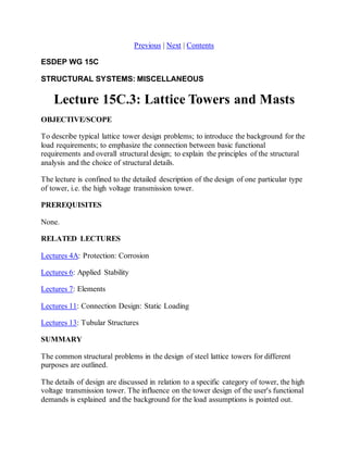
The document discusses the design of lattice towers, specifically high voltage transmission towers. It outlines the common structural design problems for towers, including establishing load requirements and ensuring consistency between loads, overall design, and structural detailing. The document then focuses on the specific design of high voltage transmission towers, describing their functional requirements, typical loads, overall truss configurations, structural analysis approaches, and considerations for joint detailing.
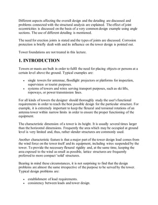
![For a cantilever structure, the tower legs are usually given a taper in both main
directions enabling the designer to choose the same structural section on a
considerable part of the tower height. The taper is also advantageous with regard to
the bracing, as it reduces the design forces (except for torsional loads).
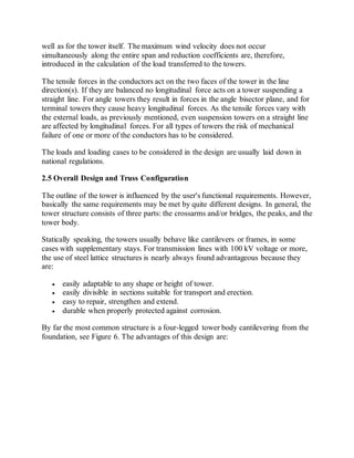
The bracing of the tower faces is chosen either as a single lattice, a cross bracing or a
K-bracing, possibly with redundant members reducing the buckling length of the leg
members, for example see Figure 6. The choice of bracing depends on the size of the
load and the member lengths. The most common type is cross bracing. Its main
advantage is that the buckling length of the brace member in compression is
influenced positively by the brace member in tension, even with regard to deflection
perpendicular to the tower face.
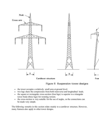
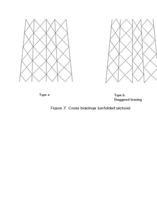
Generally, the same type of bracing is chosen for all four tower body faces, most
frequently with a staggered arrangement of the nodes, see Figure 7. This arrangement
provides better space for the connections, and it may offer considerable advantage
with respect to the buckling load of the leg members. This advantage applies
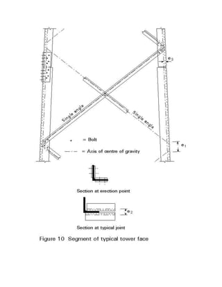
especially to angle sections when used as shown in Figures 10 and 11, since it
diminishes the buckling length for buckling about the 'weak' axis v-v. For further
study on this matter see [1].](https://image.slidesharecdn.com/3-141020232027-conversion-gate02/85/HV-tower-design-3-13-320.jpg)

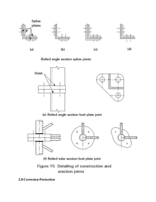
![Today, corrosion protection of steel lattice towers is almost synonymous with hot-galvanising,
possibly with an additional coating. The process involves dipping the
structural components into a galvanic bath to apply a zinc layer, usually about
100 m thick.
No welding should be performed after galvanizing, as it damages the protection. The
maximum size of parts to be galvanized is limited by the size of the available galvanic
bath.
3. CONCLUDING SUMMARY
The overall design of a lattice tower is very closely connected with the user's
functional requirements. The requirements must be studied carefully.
A major part of the design loads on the tower results from the wind force on
tower and equipment.
The occurrence of an ice cover on the tower and equipment must be considered
in the design.
For towers supporting wires, differential loads in the wire direction must be
taken into account.
For systems of interconnected towers it must be considered that the collapse of
one tower may influence the stability of a neighbouring tower.
In most cases a cantilevered tower with four legs is preferred, as it offers
structural advantages and occupies a relatively small ground area.
The type of bracing greatly affects the stability of both legs and braces. K-bracings
and/or staggered cross bracings are generally found advantageous.
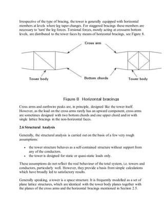
Horizontal braces at certain levels of the tower add considerably to its torsional
rigidity.
Angle sections are widely used in towers with a square or rectangular base, as
they permit very simple connection design.
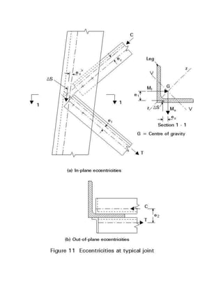
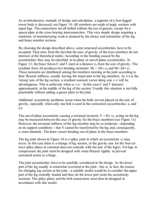
Both in-plane and out-of-plane eccentricities in the connections must be
considered.
A proper, long lasting corrosion protection must be provided. The protection
method influences the structural design.
4. REFERENCES
[1] European Convention for Constructional Steelwork, ECCS, "Recommendations
for Angles in Lattice Transmission Towers", ECCS Technical Committee 8, Brussels
1985.](https://image.slidesharecdn.com/3-141020232027-conversion-gate02/85/HV-tower-design-3-25-320.jpg)