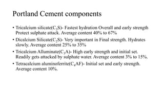
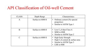
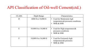
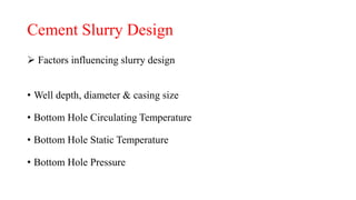
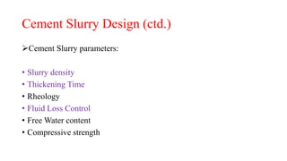
Classification of Cement;
Slurry Design & Additives
Chirag Vanecha
16BPE137
SPT, PDPU.
Faculty Mentor: Mr. Chandan Sahu
Well Cementing
• Well cementing is the process
of introducing cement to the
annular space between the
well-bore and casing or to the
annular space between two
successive casing strings.
• Cement Sheath??
Functions of Cement
 In an oil/ gas well, the primary functions of cement are:
• Provide zonal isolation
• Support axial load of casing strings
• Provide casing support and protection against corrosive fluids
• Support the borehole
Portland Cement components
• Tricalcium silicate(C3S)- Fastest hydration Overall and early strength
Protect sulphate attack. Average content 40% to 67%
• Dicalcium Silicate(C2S)- Very important in Final strength. Hydrates
slowly. Average content 25% to 35%
• Tricalcium Alluminate(C3A)- High early strength and initial set.
Readily gets attacked by sulphate water. Average content 3% to 15%.
• Tetracalcium aluminoferrite(C4AF)- Initial set and early strength.
Average content 10%.
API Classification of Oil-well Cement
CLASS Depth Range Characteristics
A Surface to 6000 ft • Ordinary cement (No special
properties)
• Similar to ASTM Type 1
B Surface to 6000 ft • Low C3A than Class A
• MSR to HSR
• Similar to ASTM Type 2
C Surface to 6000 ft • High Early Strength
• High C3S content & surface area
• Similar to ASTM Type 3
• LSR to HSR
API Classification of Oil-well Cement(ctd.)
CLASS Depth Range Characteristics
D 6000 ft to 10,000 ft • Used for Moderately high
temperatures& pressures conditions
• MSR & HSR
E 10.000 ft to 14,000 ft • Used for High temperatures&
pressures conditions
• MSR & HSR
F 10,000 ft to 16,000 ft • Used for Extremely high
temperatures& pressures
• MSR & HSR
API Classification of Oil-well Cement(ctd.)
CLASS Depth Range Characteristics
G& H • Basic cement from
surface to 8000 ft
• All depths
• Can cover wide range of depth and
temperature with accelerators and
retarders
• MSR& HSR
• No additions other than calcium
sulphate or water or both
J 12.000 ft to 16,000 ft • Can cover wide range of depth and
extremely high temperatures with
accelerators and retarders
• MSR& HSR
• No additions other than calcium
sulphate or water or both
Cement Slurry Design
 Factors influencing slurry design
• Well depth, diameter & casing size
• Bottom Hole Circulating Temperature
• Bottom Hole Static Temperature
• Bottom Hole Pressure
Cement Slurry Design (ctd.)
Cement Slurry parameters:
• Slurry density
• Thickening Time
• Rheology
• Fluid Loss Control
• Free Water content
• Compressive strength
Slurry Density
• Should be the same as mud to minimize the risk or blowouts or lost
circulation
• Measured using mud balance
• Low density are prepared with bentonite, pozzolan, gilsonite, perlite,
Diatomaceous earth
• Bentonite is used in concentration up to 35%, the reduction is due to
water added. more water requires for bentonite addition.
• Density increases by adding barite, iron ores or galena
Thickening time
• Determine the length of time the slurry can be pumped
• It is the time necessary for the slurry consistency to reach 100 poises
(70 poises is the maximum pumpable viscosity)
• Thickening time can be modified by Additives(accelerators/retarders)
• In practice the thickening time should be at least 25% higher than the
time necessary to accomplish the operation
Cement Additives
• Accelerators
• Retarders
• Dispersant-Also called friction reducers, these materials make cement
slurries easier to mix and pump by making them less viscous.
Enhances fluid loss control.
• Fluid Loss additives
• Anti-Gas migration additives-Gas migration control additives are used
to reduce the risk of gas invading the cement and migrating into the
wellbore.
Accelerators
• Are used to reduce the thickening time (minimizes the waiting period)
• Used for shallow wells and surface casings and low temperatures
zones
• Examples: Calcium Chloride
Sodium Chloride/Sea water for mixing
Potassium Chloride
Gypsum
Sodium silicate
Retarders
• Are used to increase the thickening time (waiting period is increased)
• Retarders are used for cementing deep and hot wells.
• Examples:
Calcium lignosulphonate (increases thickening time with low
concentrations)
Calcium lignosulphonate + organic acid (high temperature conditions)
Calcium-sodium lignosulphonate when bentonite is used in slurry
Sodium tetraborate (borax)
Carboxymethyl hydroxymethyl cellulose
Fluid Loss Control
• It is important to limit the loss of water filtrate from a slurry to a
permeable formation.
• Reasons:
Minimize hydration of water sensitive formations
Limit the increase in slurry viscosity
Allow for sufficient water to be available for cement hydration
• Examples of filtration control additives:
latex, organic polymers(cellulose), Polyallylamine
Cement& slurry design

Cement& slurry design

  • 1.
    Classification of Cement; SlurryDesign & Additives Chirag Vanecha 16BPE137 SPT, PDPU. Faculty Mentor: Mr. Chandan Sahu
  • 2.
    Well Cementing • Wellcementing is the process of introducing cement to the annular space between the well-bore and casing or to the annular space between two successive casing strings. • Cement Sheath??
  • 3.
    Functions of Cement In an oil/ gas well, the primary functions of cement are: • Provide zonal isolation • Support axial load of casing strings • Provide casing support and protection against corrosive fluids • Support the borehole
  • 4.
    Portland Cement components •Tricalcium silicate(C3S)- Fastest hydration Overall and early strength Protect sulphate attack. Average content 40% to 67% • Dicalcium Silicate(C2S)- Very important in Final strength. Hydrates slowly. Average content 25% to 35% • Tricalcium Alluminate(C3A)- High early strength and initial set. Readily gets attacked by sulphate water. Average content 3% to 15%. • Tetracalcium aluminoferrite(C4AF)- Initial set and early strength. Average content 10%.
  • 5.
    API Classification ofOil-well Cement CLASS Depth Range Characteristics A Surface to 6000 ft • Ordinary cement (No special properties) • Similar to ASTM Type 1 B Surface to 6000 ft • Low C3A than Class A • MSR to HSR • Similar to ASTM Type 2 C Surface to 6000 ft • High Early Strength • High C3S content & surface area • Similar to ASTM Type 3 • LSR to HSR
  • 6.
    API Classification ofOil-well Cement(ctd.) CLASS Depth Range Characteristics D 6000 ft to 10,000 ft • Used for Moderately high temperatures& pressures conditions • MSR & HSR E 10.000 ft to 14,000 ft • Used for High temperatures& pressures conditions • MSR & HSR F 10,000 ft to 16,000 ft • Used for Extremely high temperatures& pressures • MSR & HSR
  • 7.
    API Classification ofOil-well Cement(ctd.) CLASS Depth Range Characteristics G& H • Basic cement from surface to 8000 ft • All depths • Can cover wide range of depth and temperature with accelerators and retarders • MSR& HSR • No additions other than calcium sulphate or water or both J 12.000 ft to 16,000 ft • Can cover wide range of depth and extremely high temperatures with accelerators and retarders • MSR& HSR • No additions other than calcium sulphate or water or both
  • 8.
    Cement Slurry Design Factors influencing slurry design • Well depth, diameter & casing size • Bottom Hole Circulating Temperature • Bottom Hole Static Temperature • Bottom Hole Pressure
  • 9.
    Cement Slurry Design(ctd.) Cement Slurry parameters: • Slurry density • Thickening Time • Rheology • Fluid Loss Control • Free Water content • Compressive strength
  • 10.
    Slurry Density • Shouldbe the same as mud to minimize the risk or blowouts or lost circulation • Measured using mud balance • Low density are prepared with bentonite, pozzolan, gilsonite, perlite, Diatomaceous earth • Bentonite is used in concentration up to 35%, the reduction is due to water added. more water requires for bentonite addition. • Density increases by adding barite, iron ores or galena
  • 11.
    Thickening time • Determinethe length of time the slurry can be pumped • It is the time necessary for the slurry consistency to reach 100 poises (70 poises is the maximum pumpable viscosity) • Thickening time can be modified by Additives(accelerators/retarders) • In practice the thickening time should be at least 25% higher than the time necessary to accomplish the operation
  • 12.
    Cement Additives • Accelerators •Retarders • Dispersant-Also called friction reducers, these materials make cement slurries easier to mix and pump by making them less viscous. Enhances fluid loss control. • Fluid Loss additives • Anti-Gas migration additives-Gas migration control additives are used to reduce the risk of gas invading the cement and migrating into the wellbore.
  • 13.
    Accelerators • Are usedto reduce the thickening time (minimizes the waiting period) • Used for shallow wells and surface casings and low temperatures zones • Examples: Calcium Chloride Sodium Chloride/Sea water for mixing Potassium Chloride Gypsum Sodium silicate
  • 14.
    Retarders • Are usedto increase the thickening time (waiting period is increased) • Retarders are used for cementing deep and hot wells. • Examples: Calcium lignosulphonate (increases thickening time with low concentrations) Calcium lignosulphonate + organic acid (high temperature conditions) Calcium-sodium lignosulphonate when bentonite is used in slurry Sodium tetraborate (borax) Carboxymethyl hydroxymethyl cellulose
  • 15.
    Fluid Loss Control •It is important to limit the loss of water filtrate from a slurry to a permeable formation. • Reasons: Minimize hydration of water sensitive formations Limit the increase in slurry viscosity Allow for sufficient water to be available for cement hydration • Examples of filtration control additives: latex, organic polymers(cellulose), Polyallylamine