Project report on multi storied building expertcivil
This document is a project report on the design and analysis of a multi-storied building. It includes a certificate stating that it is a bonafide report of the project work carried out by three students to fulfill the requirements for a Bachelor of Engineering degree. The report contains chapters on the project background, literature review, architectural design, structural analysis using STAAD Pro software, structural design of building elements like foundations, columns, beams and slabs, loading considerations, and conclusions. Drawings of the building are also included.
Certification of K. Uday Kumar et al. for the project on 'Multi-storied Building Design and Analysis', under the supervision of V. Gajendra during 2011-2012.
Overview of project chapters including introduction, literature survey, design considerations, and analyses conducted using STAAD Pro, culminating in structural design.
Introduction to the project detailing the aims, safety requirements, design considerations (IS456-2000), and geometric conditions of the residential multistoried building.
Discussion on historical architectural advancements, household definitions, and the evolution of architectural thinking through cultural and political lenses.
Exploration of architecture as the art and science of building design, emphasizing modernist principles, function over form, and sustainability in design.
Architectural layout drawings and the process of structural analysis involving load resistance, safety, and structural performance goals.
Introduction to STAAD Pro capabilities in structural design, including steps for creating models, applying loads, and analysis output.
Detailed features of STAAD Pro like dynamic analysis, load generation capabilities, and its compliance with international design codes.
In-depth discussion on structural design of multistoried building components including slabs, beams, columns, and foundations, with related calculations.
Identifying design loads such as dead, live, and imposed loads essential for building safety and structural integrity.
Example analysis process using STAAD Pro with load specifications and procedural input information for structural modeling.
Summarization of loading analysis findings and their implications on structural safety and performance outcomes.
Calculations for footing design based on factored loads, shear forces, and permissible stresses, ensuring foundation safety.
Design considerations for staircases including load calculations, bending moments, safety checks, and reinforcement details.Project conclusions emphasizing STAAD Pro's importance in modern structural engineering and listing key references for future study.
Project report on multi storied building expertcivil
1.
GOKARAJU RANGARAJU INSTITUTEOF ENGINEERING AND TECHNOLOGY
JAWAHARLAL NEHRU TECHNOLOGICAL UNIVERSITY
DEPARTMENT OF CIVIL ENGINEERING
CERTIFICATE
Certified that this is the bonafide report of the project work of
“Analysis and Design of Multi-storied building”
Carried out by
K.UDAY KUMAR (09245A0103)
K.NAGENDRA BABU (08241A0123)
MD.KHAJA THAQUIDDIN (08241A0117)
Students of Final year during the academic year 2011-2012 in the partial fulfillment
For the award of the Degree BACHELOR OF ENGINEERING
PROJECT GUIDE EXAMINAR H.O.D OF CIVIL ENGG
2.
Project Report
On
DESIGN ANDANALYSIS
OF
MULTI-STORIED BUILDING
DEPARTMENT OF CIVIL ENGINEERING
(2011-2012)
Under the guidance of
V.Gajendra
M.E ( Transportation Engg)
Associate professor
(Civil Engineering Department)
BY
K.UDAY KUMAR (09245A0103)
K.NAGENDRA BABU (08241A0123)
MD.KHAJA THAQUIDDIN (08241A0117)
Gokaraju Rangaraju Institute of Engineering & Technology
Jawaharlal Nehru Technological University
Hyderabad
3.
Project Report
On
DESIGN ANDANALYSIS
OF
MULTI-STORIED BUILDING
A Dissertation submitted in partial fulfillment of
the requirement for the award of degree of
Bachelor of Technology
In
CIVIL ENGINEERING
By
K.UDAY KUMAR (09245A0103)
K.NAGENDRA BABU (08241A0123)
MD.KHAJA THAQUIDDIN (08241A0117)
DEPARTMENT OF CIVIL ENGINEERING
GOKARAJU RANGARAJU INSTITUTE OF ENGINEERING AND TECHNOLOGY
JAWAHARLAL NEHRU TECHNOLOGICAL UNIVERSITY
NIZAMPET ROAD,HYDERABAD-500090
4.
CONTENTS
S. No: TopicPage no.
1. CHAPTER—1
Introduction 4
Statement of the Project 6
2. CHAPTER—2
Literature survey 7
3. CHAPTER—3
Architecture 9
4. CHAPTER—4
Architectural layout drawing 13
5. CHAPTER—5
Introduction to structural Analysis 16
6. CHAPTER—6
5.
Staad pro 19
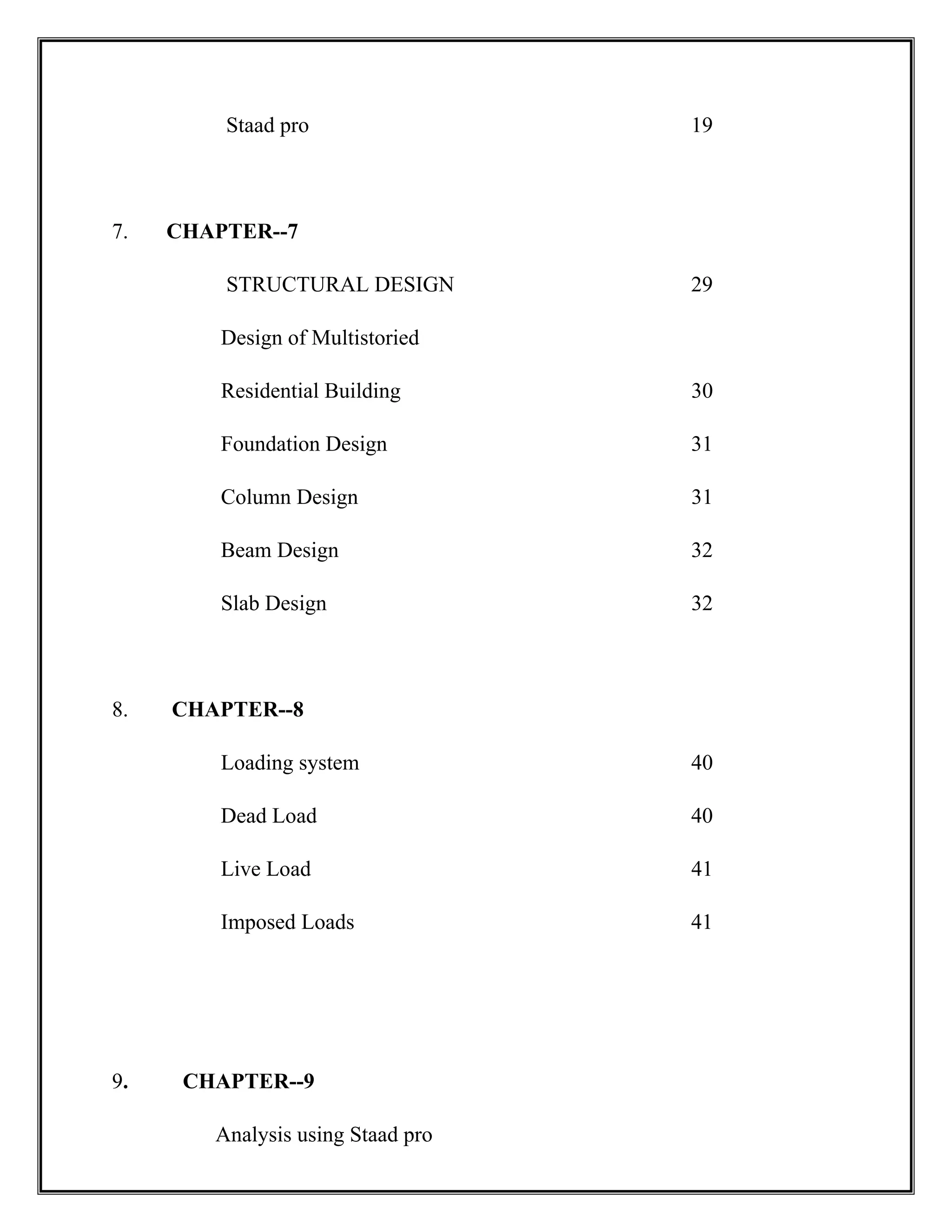
7.CHAPTER--7
STRUCTURAL DESIGN 29
Design of Multistoried
Residential Building 30
Foundation Design 31
Column Design 31
Beam Design 32
Slab Design 32
8. CHAPTER--8
Loading system 40
Dead Load 40
Live Load 41
Imposed Loads 41
9. CHAPTER--9
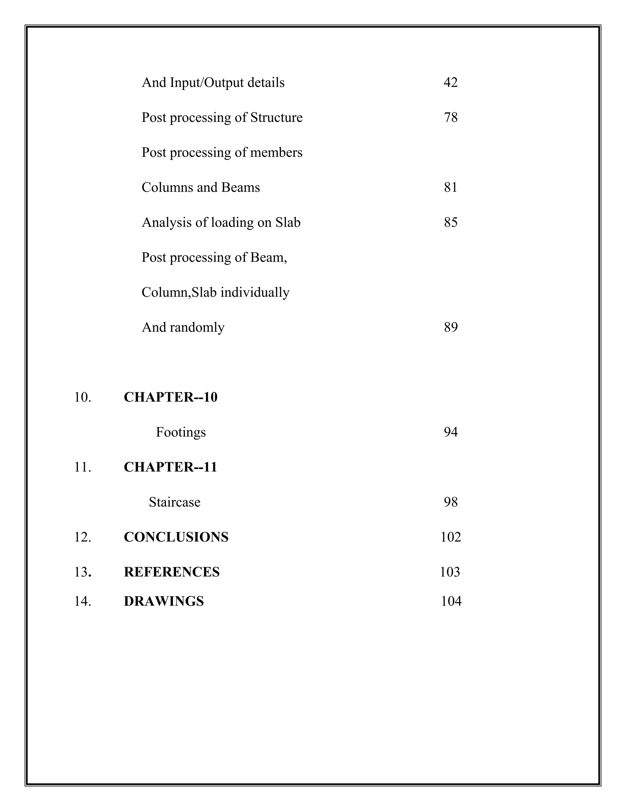
Analysis using Staad pro
6.
And Input/Output details42
Post processing of Structure 78
Post processing of members
Columns and Beams 81
Analysis of loading on Slab 85
Post processing of Beam,
Column,Slab individually
And randomly 89
10. CHAPTER--10
Footings 94
11. CHAPTER--11
Staircase 98
12. CONCLUSIONS 102
13. REFERENCES 103
14. DRAWINGS 104
7.
CHAPTER – 1
INTRODUCTION
INTRODUCTION
AIM
Ourmain aim to complete a Multi-storey building is to ensure that the structure is safe
against all possible loading conditions and to full fill the function for which they have built.
8.
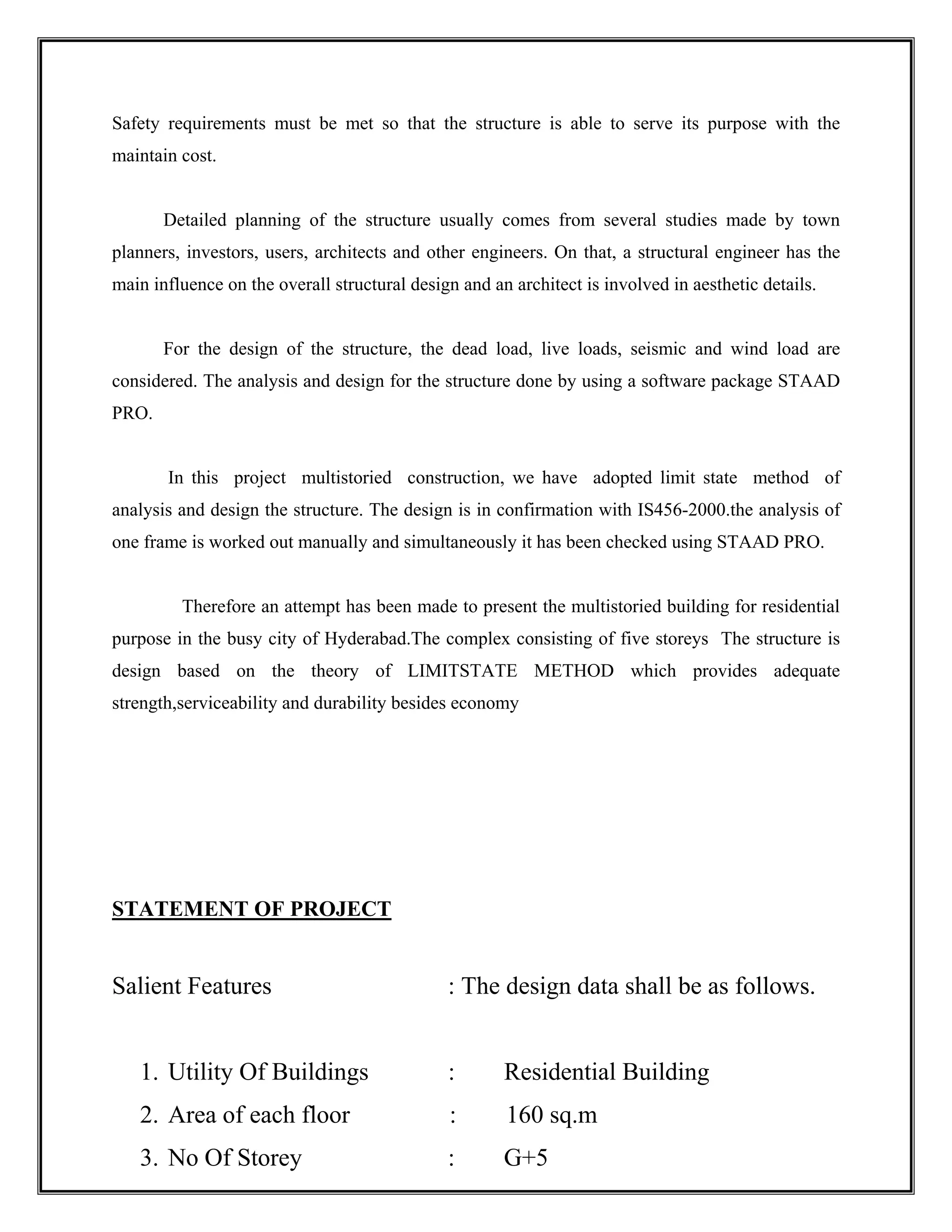
Safety requirements mustbe met so that the structure is able to serve its purpose with the
maintain cost.
Detailed planning of the structure usually comes from several studies made by town
planners, investors, users, architects and other engineers. On that, a structural engineer has the
main influence on the overall structural design and an architect is involved in aesthetic details.
For the design of the structure, the dead load, live loads, seismic and wind load are
considered. The analysis and design for the structure done by using a software package STAAD
PRO.
In this project multistoried construction, we have adopted limit state method of
analysis and design the structure. The design is in confirmation with IS456-2000.the analysis of
one frame is worked out manually and simultaneously it has been checked using STAAD PRO.
Therefore an attempt has been made to present the multistoried building for residential
purpose in the busy city of Hyderabad.The complex consisting of five storeys The structure is
design based on the theory of LIMITSTATE METHOD which provides adequate
strength,serviceability and durability besides economy
STATEMENT OF PROJECT
Salient Features : The design data shall be as follows.
1. Utility Of Buildings : Residential Building
2. Area of each floor : 160 sq.m
3. No Of Storey : G+5
9.
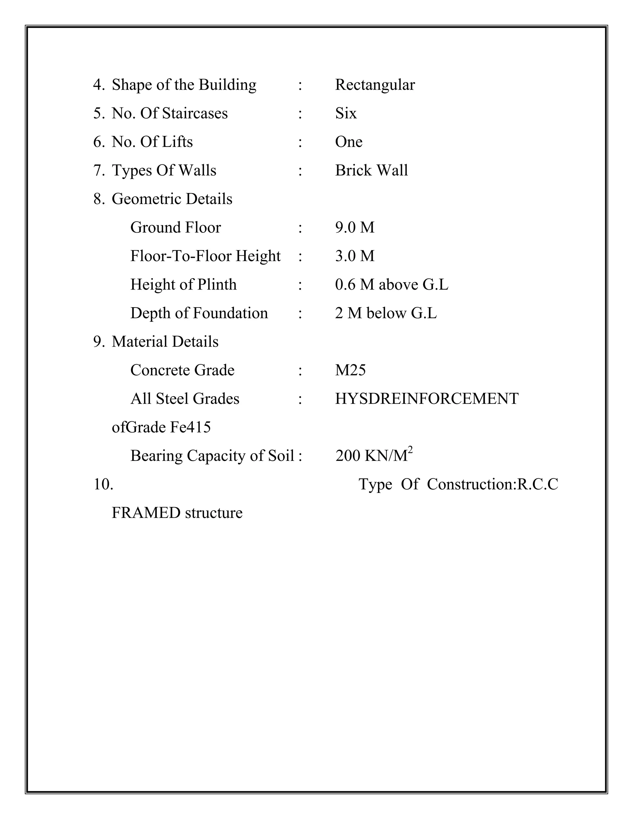
4. Shape ofthe Building : Rectangular
5. No. Of Staircases : Six
6. No. Of Lifts : One
7. Types Of Walls : Brick Wall
8. Geometric Details
Ground Floor : 9.0 M
Floor-To-Floor Height : 3.0 M
Height of Plinth : 0.6 M above G.L
Depth of Foundation : 2 M below G.L
9. Material Details
Concrete Grade : M25
All Steel Grades : HYSDREINFORCEMENT
ofGrade Fe415
Bearing Capacity of Soil : 200 KN/M2
10. Type Of Construction:R.C.C
FRAMED structure
10.
CHAPTER – 2
LITERATURESURVEY
LITERATURE SURVEY
Major advances in both design and new material assisted roman architecture. Design
was enhanced architectural developments in the construction of arches and roof domes. Arches
improved the efficiency and capability of bridges and aqueducts (fewer supports columns were
needed to support the structure), while domed roofs not only permitted the building of larger
open areas undercover, but also lent the exterior an impressive.
11.
The social unitthat lives in a house is known as a household. Most commonly, a household is
family unit of a same kind, though households can be other social groups, such as single person,
or groups of unrelated individuals. Settled agrarian and industrial societies are composed of
household units living permanently in housing of various types, according to a variety of farms
of lands tenure. English-speaking people generally call any building there routinely occupy
“home”. Many people leave their houses during the day for work and recreation, and return to
them to sleep or for other activities.
12.
CHAPTER – 3
ARCHITECTURE
ARCHITECTURE
Architectureis the art and science of designing buildings and structures. A wider definition
would include within its scope also the design of the total built environment, from the macro
level of creating furniture. In the field of building architecture, the skill demanded of an architect
range from the more complex, such as for a hospital or stadium, to the apparently simpler, such
as planning residential houses. Many architectural works may be seen also as cultural and
political symbols, and /or work of art. The role of architect though changing, has been central to
the successful design and implementation of pleasing built environments in which people live.
Scope: Architectural is an interdisciplinary field, drawing upon mathematics, science, art
technology, social sciences, politics, history and philosophy. Vitrifies states: “architecture is a
science, arising out of many other sciences, and adorned with much and varied learning: by the
help of which is judgment is formed of those works which are result of other arts”.
13.
Most modern-day definitionof “good buildings” recognize that because architecture
does not exist in a vacuum, architectural form cannot be merely a completion of historical
precedent, fictional necessities ; and socially aware concerns, but most also be a trance dents
synthesis of all of the former and a creation of worth in and of itself. As Nunziarodanini stated,
“through its aesthetic dimension architecture goes beyond the functional aspects that it has in
common with other human sciences…through its own particular way of expressing values,
architecture can stimulate and influence social life without presuming that, in and of itself, it will
promote social development. To restrict the meaning of formalism to art for art’s sake is not only
reactionary; it can be a purposeless quest for perfection or originality which degrades fro, into a
mere instrumentally”
The term can be used to connect the implied architecture of abstract things such as music or
mathematics the apparent architecture of natural things, such as geological formations or the
structure of natural things such as geological formations or the structure of natural things such as
geological formation or the structure of biological cells, or explicitly planned architectures of
human made things such as software, computers, enterprises, and databases, in addition to
buildings. In every usages an architecture may be seen as subjective mapping fro, a human
perspective (that of the user in the case of abstract or physical artifacts) to the elements or
components.
Architecture is both the process and product of planning designing and constructing
space the reflects functional, social and aesthetic considerations. It requires the manipulation and
coordination of material. Technology, light and shadow.Architecture also encompassed the
pragmatic aspects of realizing designed spaces, such as project planning, cost estimating and
construction administration.
Architectural works are often perceived as cultural and political symbols and as work of
art. Historical civilization is often identified with their surviving architectural achievements.
Brunelleschi, in the building of the dome of Florence cathedral, not only transformed the
cathedral and the city of Florence, but also the role and status of the architecture.
With the consolidation of knowledge in scientific such as engineering and the rise of
new building material and technology; the architect began to lose ground on the technical aspect
of building. Therefore he concerned playing field that of aesthetics.
There was the rise of the “gentlemen architect” who usually dealt with wealthy clients
and concentrated predominantly on visual qualities derived usually from historical prototypes. In
14.
the 19th
century, Coledes Beaux Arts in France,the training was toward producing quick sketch
schemes involving beautiful drawings without much emphasis on context. The rise of profession
of industrial design is usually placed here. Following this lead, the Bauhaus school, founded in
Germany in 1919, consciously rejected history and looked at architecture as synthesis of art craft
and technology.
Architects such as Miens van Dee roe worked to reject the virtually all that had come
before, trading handcrafted details and sentimental historic forms for a machine driven
architectural geometry made possible by the Industrial Revolution. They felt that architecture
was not a personal philosophical or aesthetic pursuit by individual rather it had to consider
everyday needs of people and use technology to give a livable environment. That design
Methodology Movement involving people such as chirrs Jones, Christopher Alexander started
for more people-oriented designs.
Extensive studies on areas such as behavioral, environmental, and social science were
done started informing the design process. as many other concerns began to be recognized,
complexity of buildings began to increase in terms of aspect to be recognized, and complexity of
buildings began to increase in terms of aspect such as services, architecture started becoming
more multi-disciplinary than ever. While the notion that structural and aesthetic consideration
should be entirely subject to functionality, which met with both popularity an skepticism, it had
the effect of introducing the concept of “function” in the place of Vitruvius “utility”. “Function”
came to be seen as encompassing all criteria of the use, perception and enjoyment of a building,
not only practical but alsoaesthetic, psychological and cultural.
“Now-a-day’s Architecture required a team of professionals in its making”.
An architect is being one among the many and sometimes the leader. This I the state of the
professional today, however, individually o still cherished and sought the design of buildings
seems as cultural symbols – the museum of fine arts centre has become a showcase for new
experiments in style, tomorrow may be something’s else.
In the late 20th
century, a new concept was added to those include in the compass of both
structure and function, the consideration of sustainability. To satisfy the contemporary ethos a
building should be a constructed in a materials, its impact upon the natural and built environment
of its surroundings area and the demands that it makes upon non-sustainable power sources for
the heating, cooling water and waste management and lighting. When modern architecture was
first practiced, it was an avant-garde movement with moral, philosophical, and aesthetic
15.
underpinnings. Modernist architectssought to reduce buildings to a pure form, removing
historical references in favors of purely fictional structures.
The column arches and gargoyles of classical architecture were dubbed unnecessary.
Buildings that flaunted their construction exposing steel beams and concrete surfaces instead of
hiding them behind traditional forms were beams and concrete surfaces instead of hiding them
behind traditional forms were seen as beautiful in their own right. Architecture first evolved out
of the dynamics between needs (shelter, security, worship etc.,) and means (available building
material and attendant skills). As human culture evolved and knowledge began to be formalized
through oral tradition and practices, architectures became a craft.
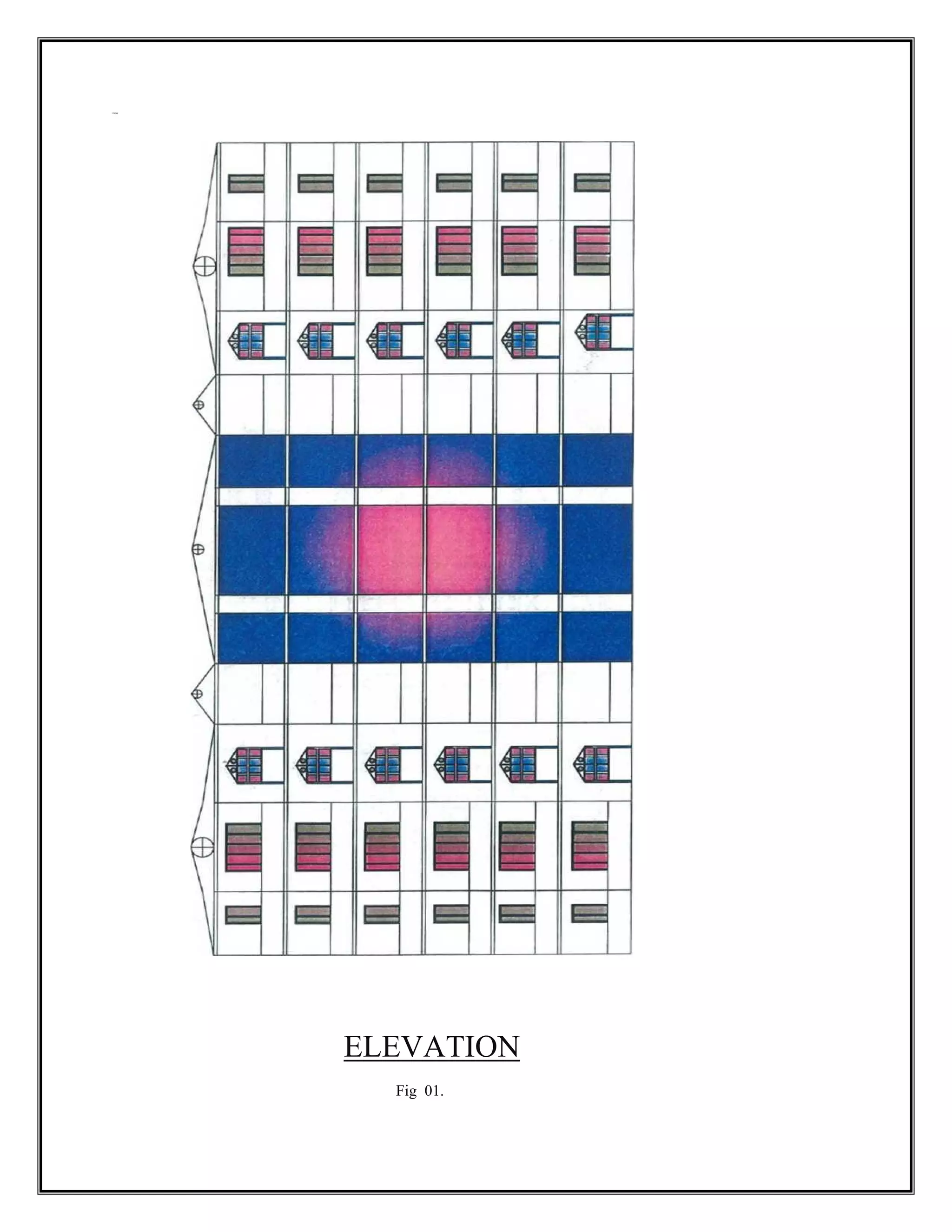
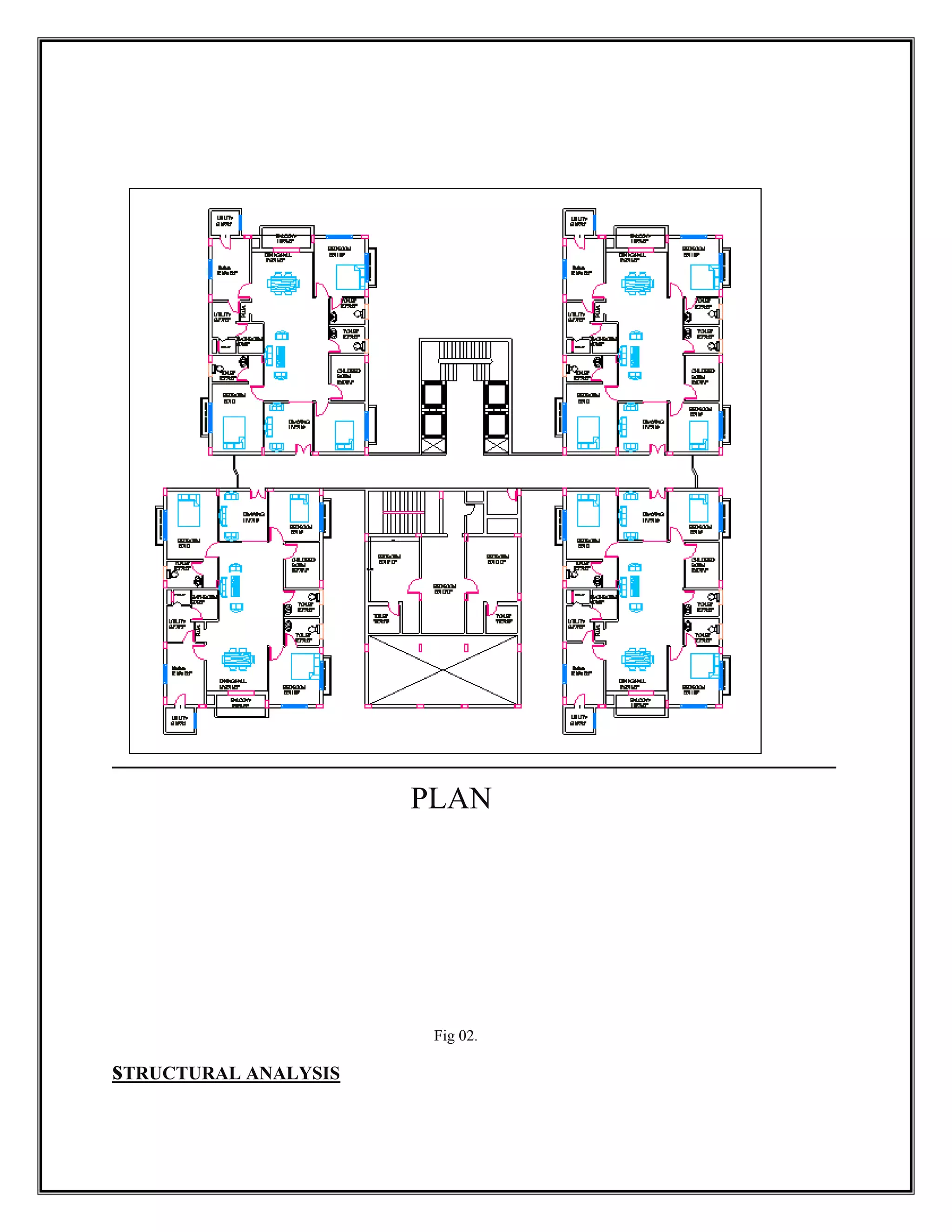
CHAPTER – 4
ARCHITECTURAL LAYOUT
DRAWINGS
The procedure ofstructural analysis is simple in concept but complex. In detail. It
involves the analysis of a proposed structure to show that its resistance or strength will meet or
exceed a reasonable expectation. This expectation is usually expressed by a specified load or
the demand and an acceptable margined of safety that constitutes a performance goal for a
structure. The performance goals structural design is multifaceted. Foremost, a structure must
perform its intended function safely over its useful life.
The concept of useful life implies consideration of durability and established the basis for
considering the cumulative exposure to time varying risks (i.e. corrosive environments, that
performance is inextricably linked to cost, owners, builders, and designer must considers
economic limit to the primary goal of safety and durability.
In the view of the above discussion, structural designer may appear to have little control
over the fundamental goals of structural design except to comply with or exceed the minimum
limits established by law. While this is generally true, a designer can still do much to optimize
the design through alternative means and methods that can for more efficient analysis techniques,
creative design detailing, and the use of innovative construction materials and methods. In
summary the goal of structural design are defined by law and reflect the collective interpretation
of general public welfare by those involved in the development and local adoption of building
could.
It is advantageous when kinematic indeterminacy< static indeterminacy. Alex Bendex first
formulated this procedure in 1914 based on the applications of compatibility and equilibrium of
compatibility and equilibrium conditions.
This method derives its name from the facts that supports and displacements are explicitly
computed. Set up simultaneous equation is formed from the solution of these parameters and the
join moment in each or computed from these values.
19.
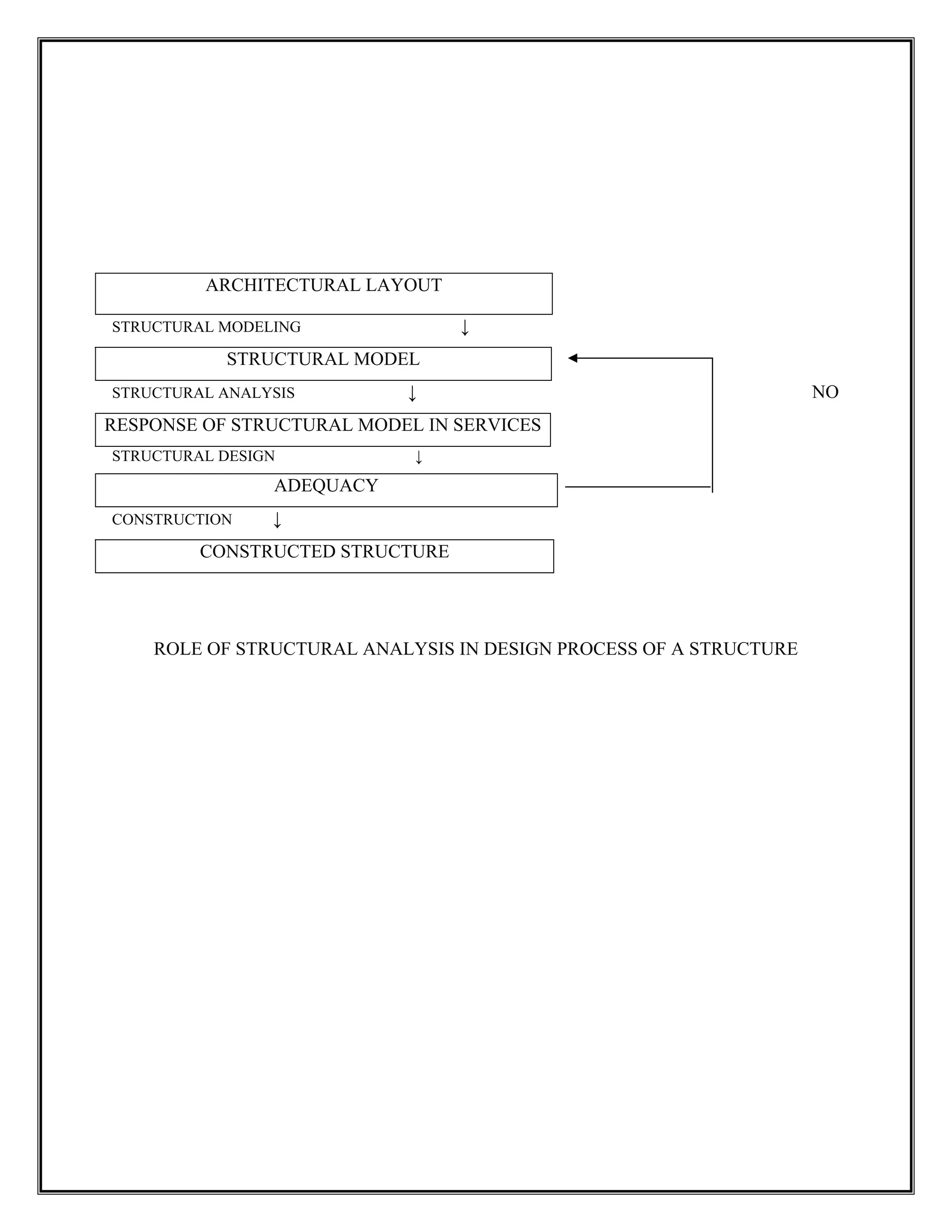
ARCHITECTURAL LAYOUT
STRUCTURAL MODELING↓
STRUCTURAL MODEL
STRUCTURAL ANALYSIS ↓ NO
RESPONSE OF STRUCTURAL MODEL IN SERVICES
STRUCTURAL DESIGN ↓
ADEQUACY
CONSTRUCTION ↓
CONSTRUCTED STRUCTURE
ROLE OF STRUCTURAL ANALYSIS IN DESIGN PROCESS OF A STRUCTURE
20.
Literature Reviews
Method ofanalysis of statically indeterminate portal frame.
I. Method of Flexibility Coefficients.
II. Slope Displacement Methods (Iterative Methods)
III. Moment Distribution Method.
IV. Kani’s Method (Approximate Method).
V. Cantilever Method.
VI. Portal Method.
VII. Matrix Method.
VIII. STADD Pro.
This chapter reviewsabout some of the fundamental concepts of structural design
and present them in a manner relevant to the design of light frame residential structures. The
concepts from the basis for understanding the design procedures and overall design
approach addressed in the remaining chapter of the guide. With this conceptual background,
it is hoped that the designer will gain a greater appreciation for creative and efficient design
of home, particularly the many assumptions that must be made.
The world is leading Structural Analysis and Design package for Structural
Engineers.
• Starting the Program.
• Creating a New Structure.
• Creating Joints and Members.
• Switching On Node and Beam Labels.
• Specifying Member Properties.
• Specifying Material Constants.
• Specifying Member Offsets.
• Printing Member Information.
• Specifying Supports.
• Specifying Loads.
• Specifying the Analysis type.
• Specifying Post-Analysis Print Commands.
• Specifying Steel Design Parameters.
• Performing Analysis and Design.
23.
• Viewing theOutput File.
Verifying results on screen both graphically and numerically.
World’s #1 Structural Analysis and Design software supporting Indian and major
International codes.
The choice of 0.2 million Structural Engineers worldwide, STAAD pro is guaranteed to
meet all your structural engineering needs.
STAADpro features state of the art user interface, visualization tools, powerful analysis and
design engines with advanced finite element (FEM) and dynamic analysis and design to
visualization and result verification STAADpro is the professional first choice. STAADpro
was developed by practicing engineers around the globe. It has evolved over 20 years and
meets the requirements of ISO 9001 certification.
STADDpro has building codes for most countries including US, Britain, Canada, Australia,
France, Germany, Spain, Norway, Finland, Sweden, India, China, Euro Zone, Japan,
Denmark and Holland.
24.
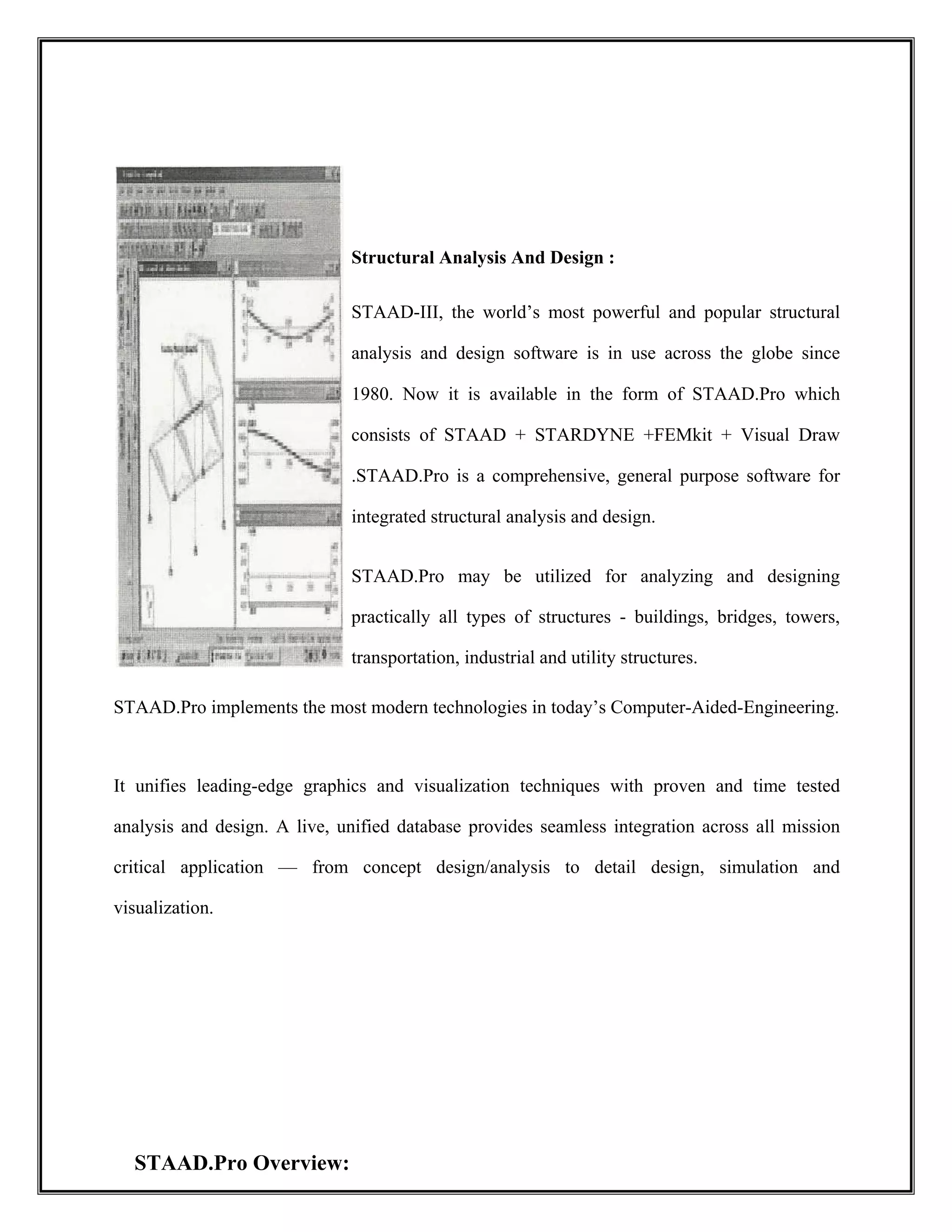
Structural Analysis AndDesign :
STAAD-III, the world’s most powerful and popular structural
analysis and design software is in use across the globe since
1980. Now it is available in the form of STAAD.Pro which
consists of STAAD + STARDYNE +FEMkit + Visual Draw
.STAAD.Pro is a comprehensive, general purpose software for
integrated structural analysis and design.
STAAD.Pro may be utilized for analyzing and designing
practically all types of structures - buildings, bridges, towers,
transportation, industrial and utility structures.
STAAD.Pro implements the most modern technologies in today’s Computer-Aided-Engineering.
It unifies leading-edge graphics and visualization techniques with proven and time tested
analysis and design. A live, unified database provides seamless integration across all mission
critical application — from concept design/analysis to detail design, simulation and
visualization.
STAAD.Pro Overview:
25.
• “Concurrent Engineering”based user environment for model development, analysis, design,
visualization and verification.
• Pull down menus, floating toolbars, tool tip help.
• Flexible Zoom and multiple views.
• Isometric and perspective views 3D shapes.
• Built-in Command File Editor.
• Simple Command Language.
• Graphics/Text input generation.
• State-of-the-art Graphical Pre and Post Processor.
• Rectangular/Cylindrical Coordinate systems.
• Joint, Member/element, Mesh Generation with flexible user-controlled numbering.
• Efficient algorithm minimizes disk space requirements.
• FPS, Metric or SI units.
Presentation quality printer plots of Geometry and Results as part of run output.
Graphics Environment:
• Model Generation
26.
o Interactive Menu-drivenModel Generation with simultaneous 3D display.
o 2D and 3D Graphic Generation using rectangular or polar coordinate system.
o Segments of repetitive geometry may be used to generate complex structural models.
o Generate Copy, Repeat, Mirror, Pivot, etc, or quick and easy geometry generation.
o Quick/easy mesh generation.
o Comprehensive graphics editing.
o Graphical Specification and Display of Properties, Loadings, Supports, Orientations.
o Import AutoCAD DXF files.
o Access to Text Editor.
• Model Verification
• 2D/3D drawings on screen as well as on plotter/printer.
• Full 3D shapes for Frames, Elements.
• Sectional views or views with listed members only.
• Isometric or any rotations for full 3D viewing.
• Display of properties, Loadings, Supports, Orientations, Joint/Member numbering,
Dimensions, Hidden line removed, etc.
• Plot manipulation according to the size, rotation, viewing origin and distance.
• Analysis & Design:
o Static Analysis
o 2D/3D analysis based on state-of-the-art Matrix method to handle extremely large job.
o Beam, Truss, Tapered Beam, Shell/Plate Bending/Plane Stress.
o Full/partial Moment Releases.
o Member Offset Specification.
o Fixed, Pinned and Spring Supports with Releases. Also inclined Supports.
27.
o Automatic SpringSupport Generator.
o Linear, P-Delta Analysis, Non-Linear Analysis with automatic load and stiffness correction.
Multiple Analysis within same run.
o Active/Inactive Members for Load-Dependent structures.
o Tension-only members and compression-only members, Multi-linear spring supports.
o CIMSTEEL Interface.
• Dynamic/Seismic Analysis
o Mass modeling, Extraction of Frequency and Mode shapes.
o Response Spectrum, Time History Analysis.
o Modal Damping Ratio for Individual Models.
o Harmonic Load Generator.
o Combination of Dynamic forces with Static loading for subsequent desing.
• Secondary Analysis
o Forces and Displacements at sections between nodes.
o Maximum and minimum force Envelopes.
Load Types and Load Generation:
• Loading for Joints, Members/Elements including Concentrated, Uniform, Linear,
Trapezoidal, Temperature, Strain, Support Displacement, Prestressed and Fixed-end Loads.
• Global, Local and Projected Loading Directions.
• Uniform or varying Element Pressure Loading on entire or selected portion of elements.
• Floor/Area Load converts load-per-area to member loads based on one-way or two-way
actions.
• Automatic Moving Load Generation as per standard AASHTO or user defined loading.
28.
• UBC 1997.AIJ/IS1893/Cypriot Seismic Load Generation.
• Automatic Wind Load Generation.
Factored Load Combinations including algebraic, absolute and SRSS combination schemes.
Finite Element Capabilities:
• Accurate and numerically Efficient Plate/Shell Element incorporating out-of-plane
shear and in-plane rotation.
• Automatic Element Mesh Generation.
• Comprehensive Element Stress Output including in-plane stresses, out-of-plane
shear, bending and principal stresses at nodal as well as user specified points.
Steel Design:
• Built-in steel tables including AISC, Australian, British, Canadian, Chinese,
European, Indian, Japanese, Korean, Russian, and South African. Shapes include I-
29.
Beam with orwithout cover plates, Channels, Angles, Double Angles,/Channels,
Pipes and Tubes.
• User-specified Design Parameters to customize design.
• Code Check, Member selection and Optimized Member Selection consisting of
Analysis/Design cycles.
• Design codes include AISC (ASD and LRFD), AASHTO. Optional codes include
ASCE52, BS5950, Canadian, Chinese, French, German, Japanese, Indian and
Scandinavian.
• Weld design for all steel shapes.
Concrete Design:
• Design of Concrete Beam/Column/Slab/Footing as per all major international codes.
• Numerical and Graphical Design outputs with complete reinforcement details.
• IS 456-2000 for RCC design implemented.
• RC detailer as per IS 456-2000 has been implemented which has given a new
dimension to RCC design never witnessed in STAAD before.
Result Verification:
• Result verification and display.
• Deflected and Mode Shapes based on Joint/Section Displacement for user-specified
loading or mode shape number.
• Bending Moment and Shear force diagrams of individual members as well as the
entire structures.
• User-controlled Scale factors for Deflected or Mode shapes.
• Force/Moment Envelope Plots as max/min for all loads.
• Stress contour plots.
• Code Performance Plots for Steel Design.
• Powerful on-line Query for analysis/design results.
30.
• Animation ofDeflected/Mode shapes, Stress Contours.
Special Features: Query and Report Generator:
• These powerful graphics based facilities provide on-screen result verification and
customized report generation. User-friendly navigation and organization of data
helps you get the information you need with a few simple clicks.
• Point and click on a member to obtain all the information on its Geometry, Cross-
sectional properties, Forces, etc. even design information such as Allowable Stresses,
Governing Code Criteria, Reinforcement layout are available.
CHAPTER -7
STRUCTURAL DESIGN
31.
Design of MultistoriedResidential Building
General:
A structure can be defined as a body, which can resist the applied loads without
appreciable deformations. Civil engineering structures are created to serve soma specific
like, Human habitation, transportation, bridges, storage etc. in safe and economical way.
A structure is assembling of individual elements like pinned elements (truss elements),
beam elements, column, shear wall slab able or arch. Structural engineering is concerned
with the planning, designing and the construction of structures.
Structural analysis involves the determination of the forces and displacements of the
structures or components of a structure that make up the structural system.
The main object of reinforced concrete design is to achieve a structure that will result in
a safe economical solution.
The objectives of the design are,
I.Slab Design.
32.
II.Beam Design.
III.column Design.
IV.FoundationDesign.
Foundation Design
Foundations are the structure elements that transfer loads from buildings or individual
column to earth this loads are to be properly transmitted foundations must be designed to
prevent excessive settlement are rotation to minimize differential settlements and to provide
adequate safety isolated footings for the multistoried buildings. These may be square rectangle
or circular in plan that the choice of types of foundation to be used in a given situation depends
on a number of factors.
1. Bearing capacity of soil.
2. Types of structure.
3. Types of loads.
4. Permissible differential settlements.
5. Economy.
Column Design
33.
A coloumn maybe defines as an element used primarily to support axial compressive
loads and with a height of at least three times its lateral dimensions. The strength of column
depends up on the strength of material, shape and size of cross section length and degree of
proportional and dedicational restrains at the ends.
1. Shape of cross section.
2. Slenderness ratio (A=L+D)
3. Type of loading, land.
4. Pattern of lateral reinforcement.
The ration of effective coloumn length to least lateral dimension is released to as
slenderness ratio.
Beam Design
A reinforced concrete beam should be able to resist tensile, compressive and shear stress
induced in it by loads on the beam.
There are three types of reinforced concrete beams.
1. Single reinforced beams.
2. Double reinforced concrete.
3. Flanged beams
Slab Design
A slab is a thin flexural member used in floor and roofs of structure to carry loads,, which
are usually supported by wall or beams along its edges. Slabs are plate elements forming
floor and roofs of buildings carrying distributed loads primarily by flexure.
One- Way Slab
34.
One-way slabs arethose in which the length is more than twice the breadth it can be simply
supported beam or continuous beam.
Two-Way Slab
When the slab is supported on four edges and aspect ratio(Ly/Lx)<2 the slabs are
designed as two way slabs. When slabs are supported to four sides two wayspanning action
occurs.
In two way slabs when loaded it bends in surface along both short and long span
direction causing bending moments in both direction.
Corners held down and bending moments coefficient obtained from table 26 of IS 456-
2000. In slabs M25 grade concrete and Fe415 grade steel is used.
Design of Slabs
Using M20 grade concrete
Fe415 Grade steel
Support width = 230mm
Span Lx = 3.755m
Longer Span Ly= 4.53m
Two adjacent edges discontinuous
Ly/Lx = 1.21<2
It is Two-way slab
Assume overall depth = 120mm
Effective depth = 100 mm
35.
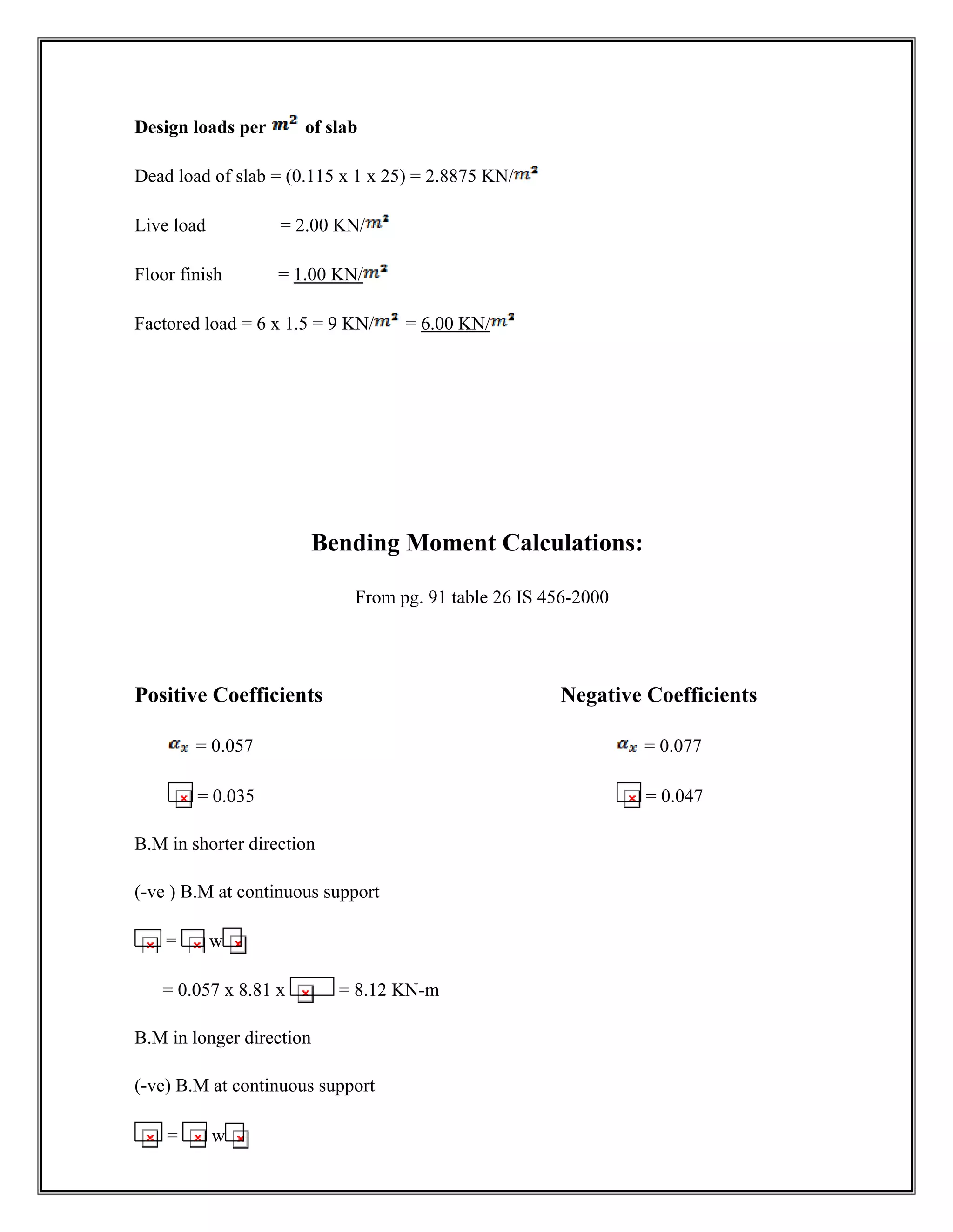
Design loads perof slab
Dead load of slab = (0.115 x 1 x 25) = 2.8875 KN/
Live load = 2.00 KN/
Floor finish = 1.00 KN/
Factored load = 6 x 1.5 = 9 KN/ = 6.00 KN/
Bending Moment Calculations:
From pg. 91 table 26 IS 456-2000
Positive Coefficients Negative Coefficients
= 0.057 = 0.077
= 0.035 = 0.047
B.M in shorter direction
(-ve ) B.M at continuous support
= w
= 0.057 x 8.81 x = 8.12 KN-m
B.M in longer direction
(-ve) B.M at continuous support
= w
36.
= 0.047 x8.81 x = 4.69 KN-m
(+ve) B.M at mid span
= w
= 0.035 x 8.81 x = 3.69 KN-m
Design Bending Moment = 8.12 KN-m
Check for effective depth
d =
= = 54.24<100 mm
Calculation of Area of steel
Minimum as per IS 456:2000
= ÎA =
A = = 204.81
(-ve) Reinforced along continuous support of short span
=0.5 [1- ] bd
=0.5 [1- ] 1000 x 100
= 236.63
Spacing of 8 mm Ø bars
37.
S= x 1000Î x 1000 = 212.39 = 210 mm c/c
Spacing should be letter of
1. 3d = 3 x 95 = 285 mm
2. 300 mm
3. Spacing calculated = 210 mm
Provide 8 mm Ø bars @ 210 mm c/c
Bent alternate bars at from the support @
Provide extra bars (top) at 400 mm c/c from the support.
=0.5 [1- ] 1000 x 100
= 141.31
Provide = 204.81
Provide 8 mm Ø bars @ 245 mm c/c
Check for shear
Shear force = = = 15.24 x N
Nominal shear stress ( ) =
38.
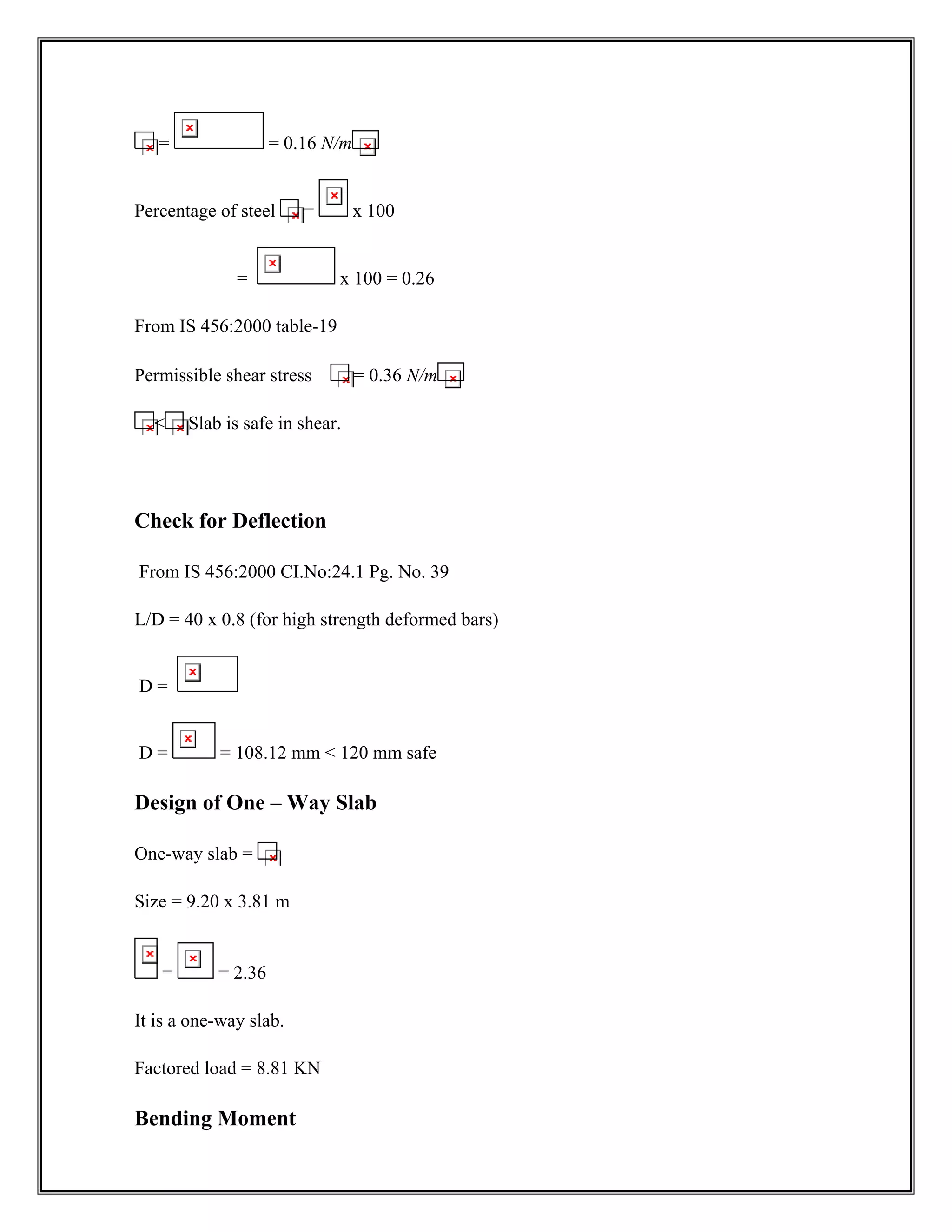
= = 0.16N/m
Percentage of steel = x 100
= x 100 = 0.26
From IS 456:2000 table-19
Permissible shear stress = 0.36 N/m
Slab is safe in shear.
Check for Deflection
From IS 456:2000 CI.No:24.1 Pg. No. 39
L/D = 40 x 0.8 (for high strength deformed bars)
D =
D = = 108.12 mm 120 mm safe
Design of One – Way Slab
One-way slab =
Size = 9.20 x 3.81 m
= = 2.36
It is a one-way slab.
Factored load = 8.81 KN
Bending Moment
39.
B.M = == 15.99 KN
Depth from moment consideration
d =
d = = 76.11 mm
Depth from stiffness consideration
D = = 119.0 mm 120 mm
d = 120-20 = 100 mm.
Calculation of area of steel
=0.5 [1- ] 1000 x 100
= 382.24 m
Spacing of 8 mm Ø bars
x 1000 = 131.48 130 mm c/c
Provide 8 mm Ø @ 120 mm c/c
Transverse reinforcement
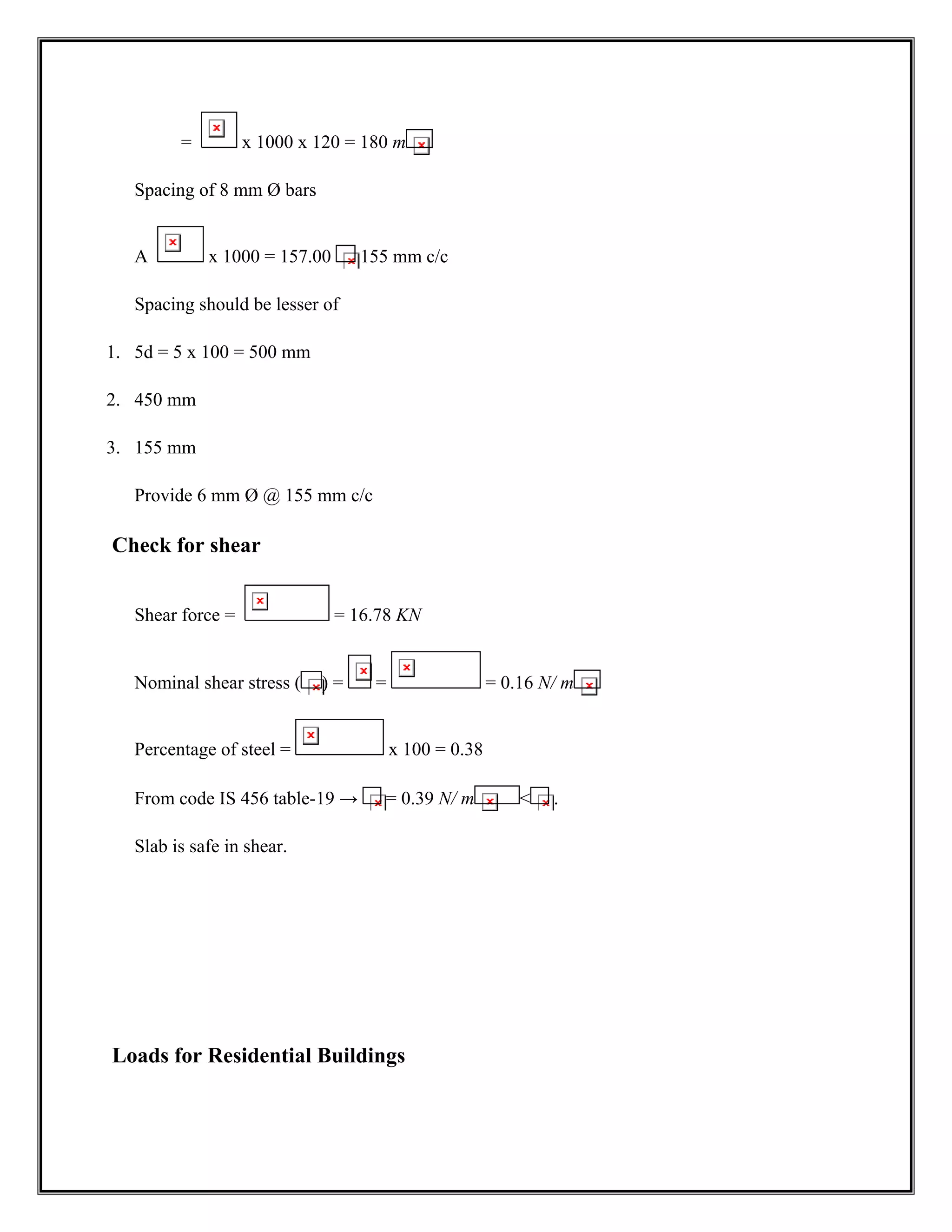
Asty = 0.15% of BD
40.
= x 1000x 120 = 180 m
Spacing of 8 mm Ø bars
A x 1000 = 157.00 155 mm c/c
Spacing should be lesser of
1. 5d = 5 x 100 = 500 mm
2. 450 mm
3. 155 mm
Provide 6 mm Ø @ 155 mm c/c
Check for shear
Shear force = = 16.78 KN
Nominal shear stress ( ) = = = 0.16 N/ m
Percentage of steel = x 100 = 0.38
From code IS 456 table-19 → = 0.39 N/ m .
Slab is safe in shear.
Loads for Residential Buildings
41.
Loads are primaryconsideration in any buildings design because they define the nature
and magnitude of hazards or external forces that a building must resist to provide reasonable
performance (i.e.; safety and serviceability) throughout the structure’s useful life.
The anticipated loads are influenced by a building’s intended use (occupancy and
function), configuration (shape and size) and location (climate and site conditions).
Ultimately, the type and magnitude of the design loads affect critical decisions such has the
material selection, construction details, and architectural configuration.
Thus to optimize the value (i.e. performance versus economy) of the finished product, it
is essential to apply design loads realistically. While the building consider in this guide are
primary single-family detached and attached dwellings, the principles and concepts related
to building loads also apply to other similar types of construction, such as low-rise
apartment’s buildings.
In general, the design loads recommended in this guide are based on:
1. Dead load.
2. Live load.
3. Imposed loads.
Dead Loads
This is the permanent of the stationary load like self weight of the structural elements.
This include the following
a) Self-weight
b) Weight of the finished structure part.
c) Weight of partition walls etc.
Dead loads are based upon the unit weights of elements, which are established taking in
account materials specified for construction, given IS 1911-1967
42.
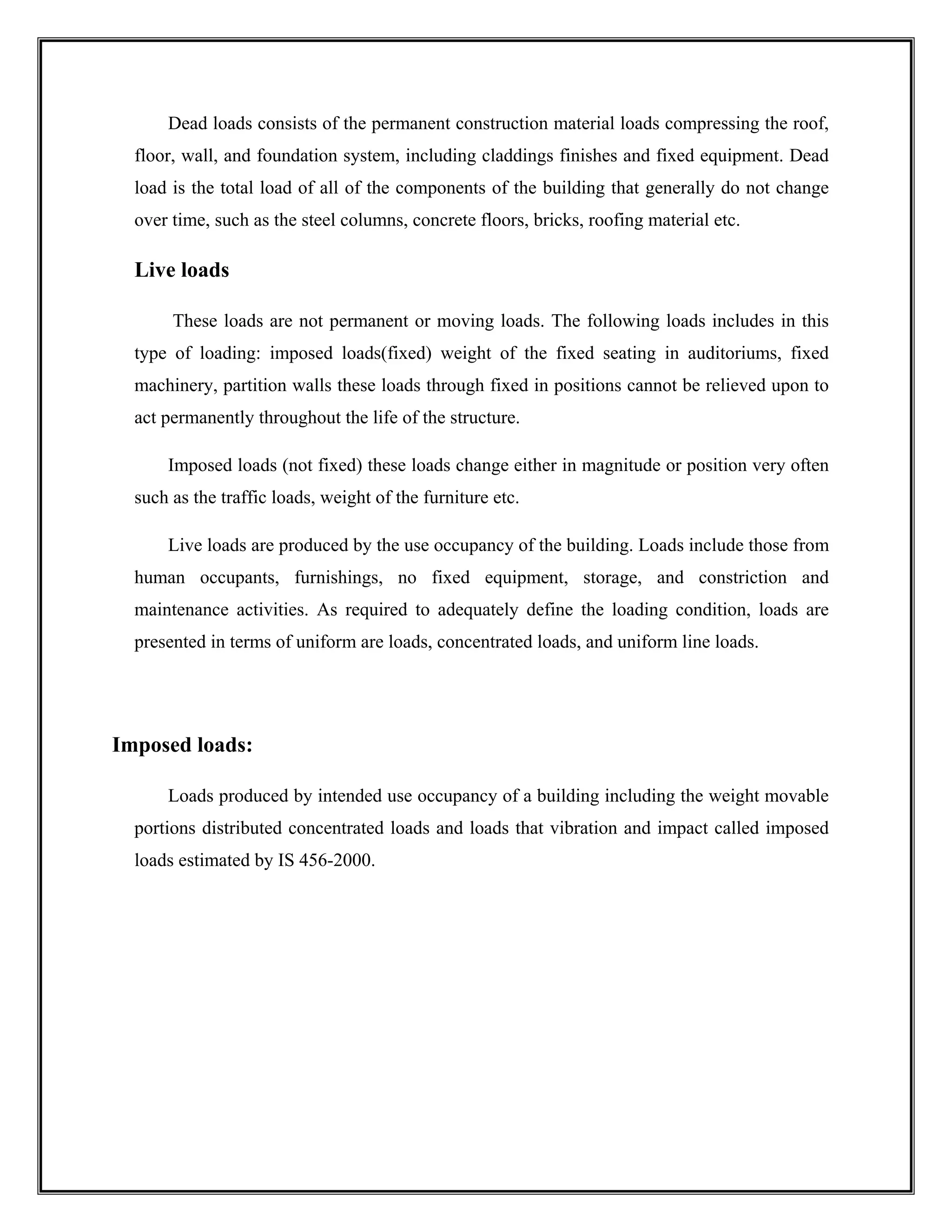
Dead loads consistsof the permanent construction material loads compressing the roof,
floor, wall, and foundation system, including claddings finishes and fixed equipment. Dead
load is the total load of all of the components of the building that generally do not change
over time, such as the steel columns, concrete floors, bricks, roofing material etc.
Live loads
These loads are not permanent or moving loads. The following loads includes in this
type of loading: imposed loads(fixed) weight of the fixed seating in auditoriums, fixed
machinery, partition walls these loads through fixed in positions cannot be relieved upon to
act permanently throughout the life of the structure.
Imposed loads (not fixed) these loads change either in magnitude or position very often
such as the traffic loads, weight of the furniture etc.
Live loads are produced by the use occupancy of the building. Loads include those from
human occupants, furnishings, no fixed equipment, storage, and constriction and
maintenance activities. As required to adequately define the loading condition, loads are
presented in terms of uniform are loads, concentrated loads, and uniform line loads.
Imposed loads:
Loads produced by intended use occupancy of a building including the weight movable
portions distributed concentrated loads and loads that vibration and impact called imposed
loads estimated by IS 456-2000.
43.
ANALYSIS BY USING
STAADPRO.
The building frame has five storeys. Concrete mix design of grade M25 and HYSD Fe415 for all
the member of the structure.
Total dead load on slab=3.8 KN/M2
Total live
on slab =2KN/M2
44.
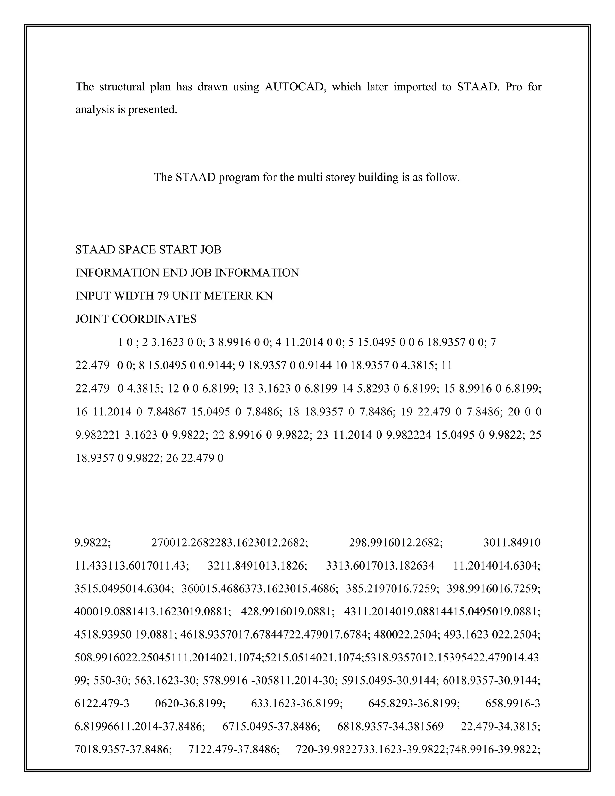
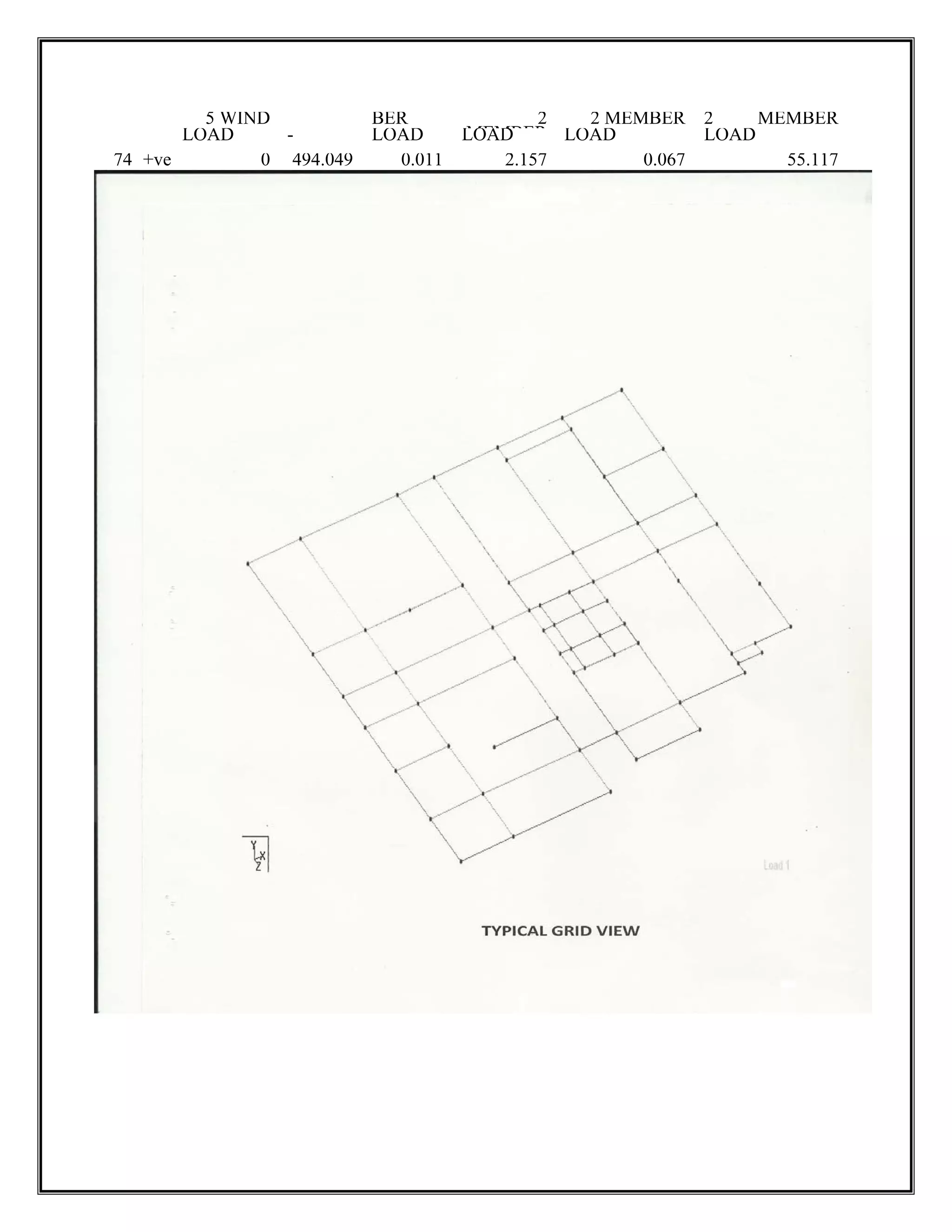
The structural planhas drawn using AUTOCAD, which later imported to STAAD. Pro for
analysis is presented.
The STAAD program for the multi storey building is as follow.
STAAD SPACE START JOB
INFORMATION END JOB INFORMATION
INPUT WIDTH 79 UNIT METERR KN
JOINT COORDINATES
1 0 ; 2 3.1623 0 0; 3 8.9916 0 0; 4 11.2014 0 0; 5 15.0495 0 0 6 18.9357 0 0; 7
22.479 0 0; 8 15.0495 0 0.9144; 9 18.9357 0 0.9144 10 18.9357 0 4.3815; 11
22.479 0 4.3815; 12 0 0 6.8199; 13 3.1623 0 6.8199 14 5.8293 0 6.8199; 15 8.9916 0 6.8199;
16 11.2014 0 7.84867 15.0495 0 7.8486; 18 18.9357 0 7.8486; 19 22.479 0 7.8486; 20 0 0
9.982221 3.1623 0 9.9822; 22 8.9916 0 9.9822; 23 11.2014 0 9.982224 15.0495 0 9.9822; 25
18.9357 0 9.9822; 26 22.479 0
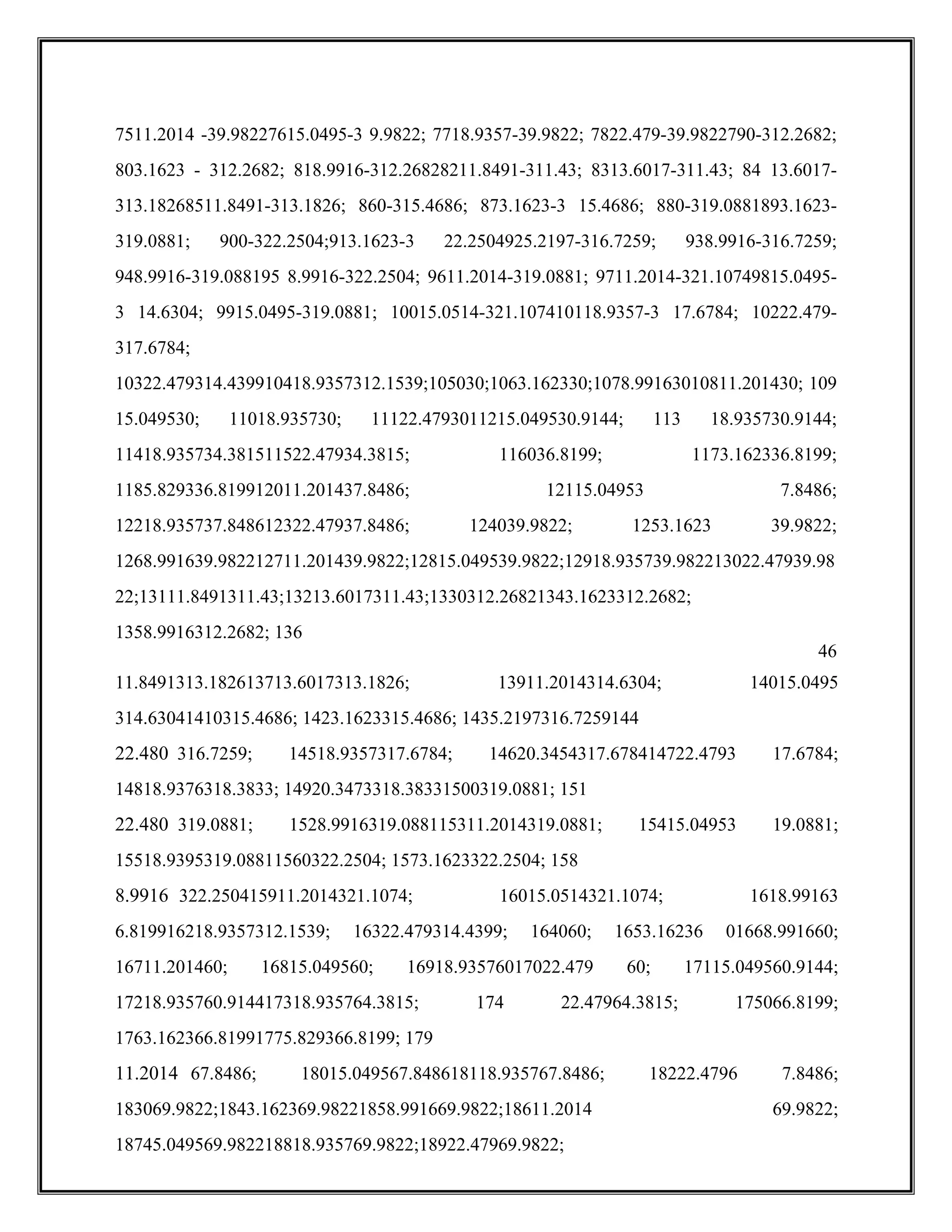
9.9822; 270012.2682283.1623012.2682; 298.9916012.2682; 3011.84910
11.433113.6017011.43; 3211.8491013.1826; 3313.6017013.182634 11.2014014.6304;
3515.0495014.6304; 360015.4686373.1623015.4686; 385.2197016.7259; 398.9916016.7259;
400019.0881413.1623019.0881; 428.9916019.0881; 4311.2014019.08814415.0495019.0881;
4518.93950 19.0881; 4618.9357017.67844722.479017.6784; 480022.2504; 493.1623 022.2504;
508.9916022.25045111.2014021.1074;5215.0514021.1074;5318.9357012.15395422.479014.43
99; 550-30; 563.1623-30; 578.9916 -305811.2014-30; 5915.0495-30.9144; 6018.9357-30.9144;
6122.479-3 0620-36.8199; 633.1623-36.8199; 645.8293-36.8199; 658.9916-3
6.81996611.2014-37.8486; 6715.0495-37.8486; 6818.9357-34.381569 22.479-34.3815;
7018.9357-37.8486; 7122.479-37.8486; 720-39.9822733.1623-39.9822;748.9916-39.9822;
ISOTROPIC CONCRETE
E 2.17185E+007
POISSON0.17
DENSITY 23.5616
ALPHA IE-005
DAMP 0.05
END DEFINE MATERIAL
MEMBER PROPERTY AMERICAN
/
1 TO 79 130 TO 139 141 TO 152 154 TO 214 265 TO 274 276 TO 287 289 TO 349 -400 TO
409 411 TO 422 424 TO 484 535 TO 544 546 TO 557 559 TO 619 - 670 TO 679 681 TO 692
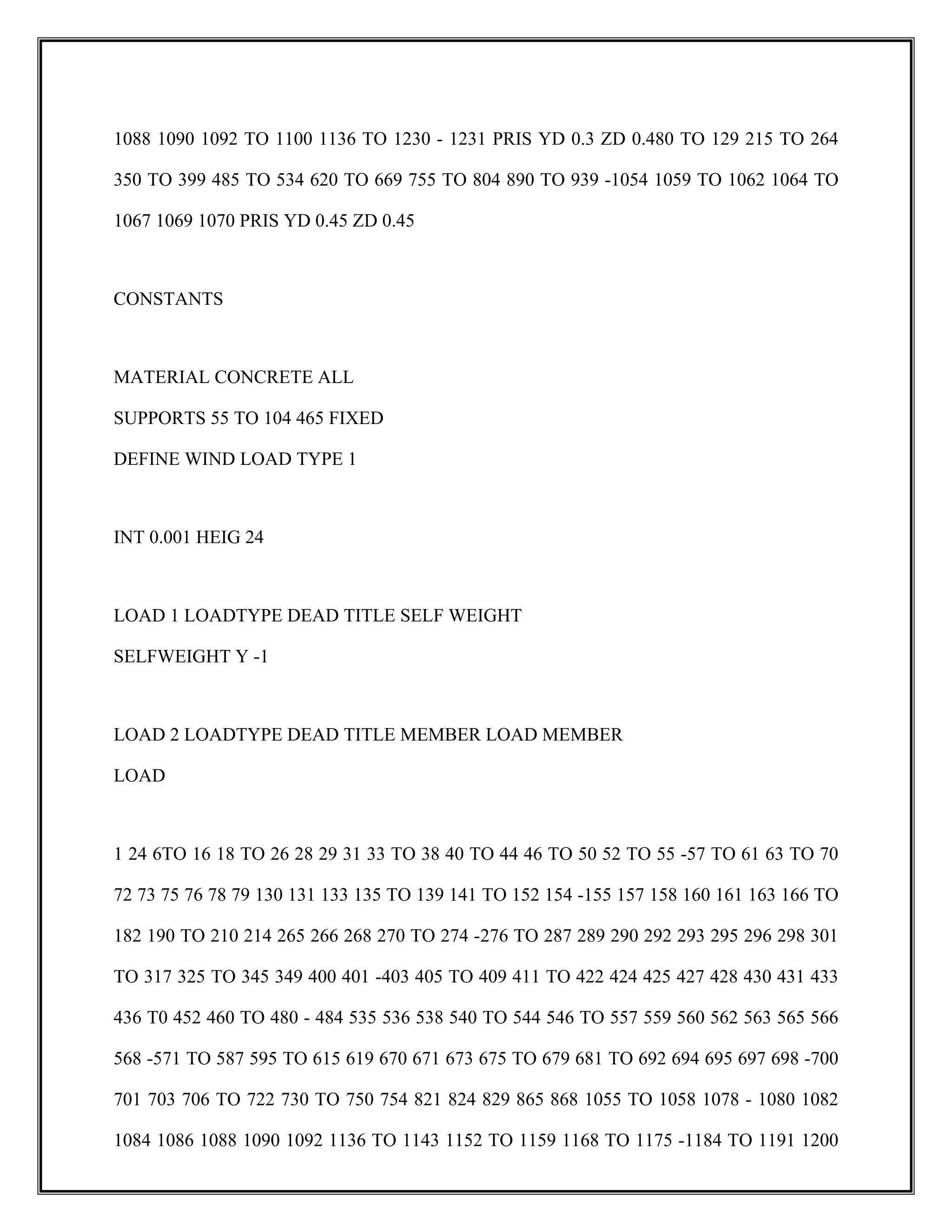
694 TO 754 805 TO 814 816 TO 827 829 TO 889 -1055 TO 1058 1078 1080 1082 1084 1086
56.
1088 1090 1092TO 1100 1136 TO 1230 - 1231 PRIS YD 0.3 ZD 0.480 TO 129 215 TO 264
350 TO 399 485 TO 534 620 TO 669 755 TO 804 890 TO 939 -1054 1059 TO 1062 1064 TO
1067 1069 1070 PRIS YD 0.45 ZD 0.45
CONSTANTS
MATERIAL CONCRETE ALL
SUPPORTS 55 TO 104 465 FIXED
DEFINE WIND LOAD TYPE 1
INT 0.001 HEIG 24
LOAD 1 LOADTYPE DEAD TITLE SELF WEIGHT
SELFWEIGHT Y -1
LOAD 2 LOADTYPE DEAD TITLE MEMBER LOAD MEMBER
LOAD
1 24 6TO 16 18 TO 26 28 29 31 33 TO 38 40 TO 44 46 TO 50 52 TO 55 -57 TO 61 63 TO 70
72 73 75 76 78 79 130 131 133 135 TO 139 141 TO 152 154 -155 157 158 160 161 163 166 TO
182 190 TO 210 214 265 266 268 270 TO 274 -276 TO 287 289 290 292 293 295 296 298 301
TO 317 325 TO 345 349 400 401 -403 405 TO 409 411 TO 422 424 425 427 428 430 431 433
436 T0 452 460 TO 480 - 484 535 536 538 540 TO 544 546 TO 557 559 560 562 563 565 566
568 -571 TO 587 595 TO 615 619 670 671 673 675 TO 679 681 TO 692 694 695 697 698 -700
701 703 706 TO 722 730 TO 750 754 821 824 829 865 868 1055 TO 1058 1078 - 1080 1082
1084 1086 1088 1090 1092 1136 TO 1143 1152 TO 1159 1168 TO 1175 -1184 TO 1191 1200
57.
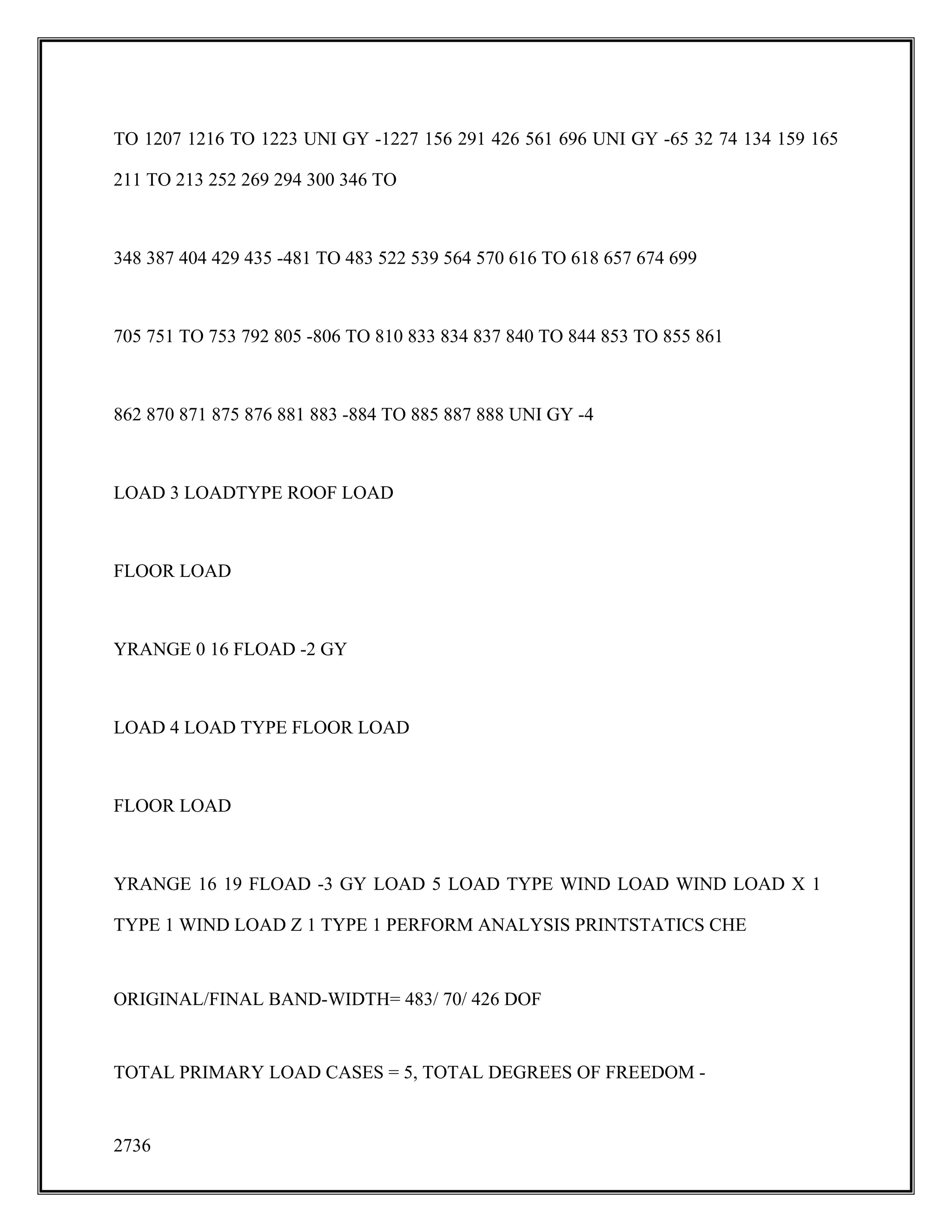
TO 1207 1216TO 1223 UNI GY -1227 156 291 426 561 696 UNI GY -65 32 74 134 159 165
211 TO 213 252 269 294 300 346 TO
348 387 404 429 435 -481 TO 483 522 539 564 570 616 TO 618 657 674 699
705 751 TO 753 792 805 -806 TO 810 833 834 837 840 TO 844 853 TO 855 861
862 870 871 875 876 881 883 -884 TO 885 887 888 UNI GY -4
LOAD 3 LOADTYPE ROOF LOAD
FLOOR LOAD
YRANGE 0 16 FLOAD -2 GY
LOAD 4 LOAD TYPE FLOOR LOAD
FLOOR LOAD
YRANGE 16 19 FLOAD -3 GY LOAD 5 LOAD TYPE WIND LOAD WIND LOAD X 1
TYPE 1 WIND LOAD Z 1 TYPE 1 PERFORM ANALYSIS PRINTSTATICS CHE
ORIGINAL/FINAL BAND-WIDTH= 483/ 70/ 426 DOF
TOTAL PRIMARY LOAD CASES = 5, TOTAL DEGREES OF FREEDOM -
2736
58.
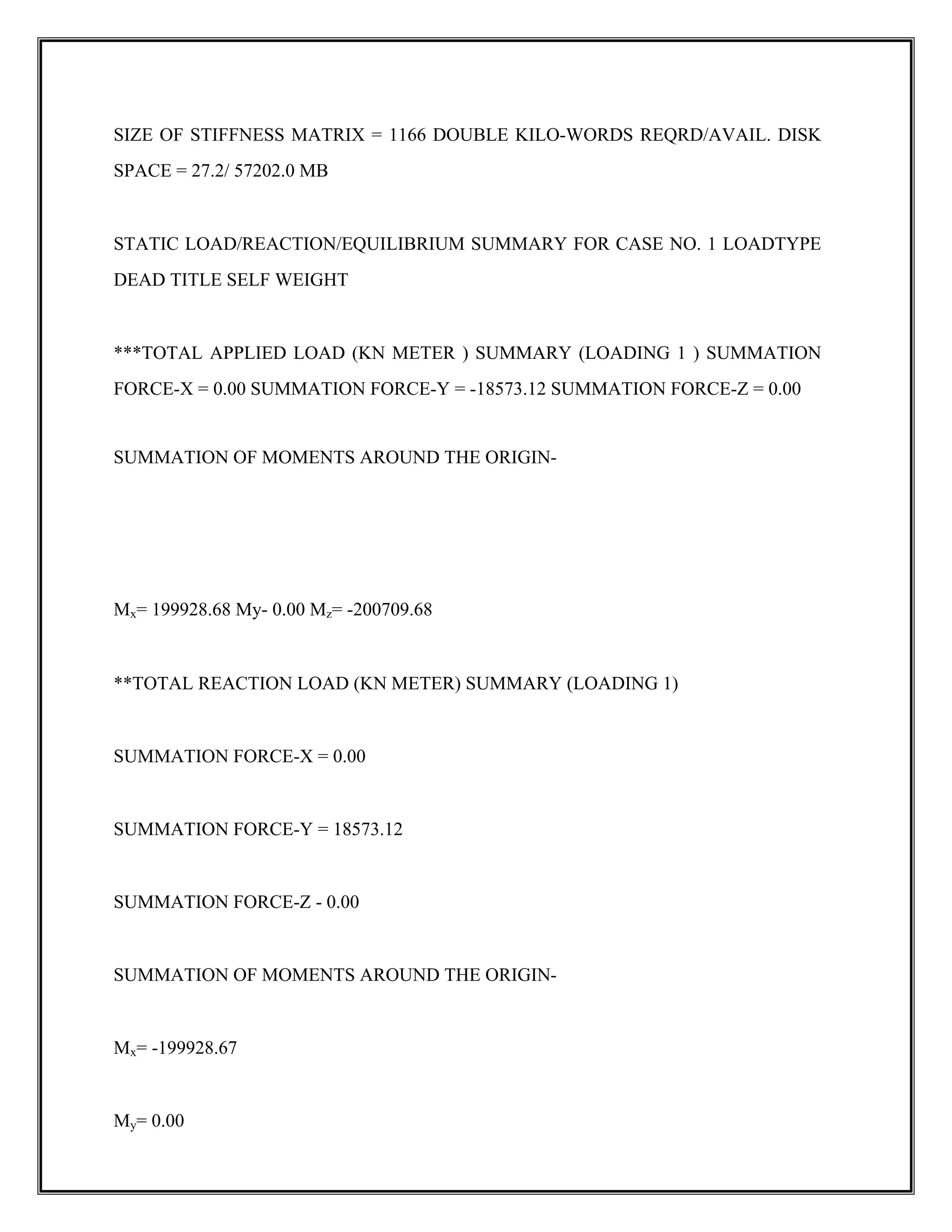
SIZE OF STIFFNESSMATRIX = 1166 DOUBLE KILO-WORDS REQRD/AVAIL. DISK
SPACE = 27.2/ 57202.0 MB
STATIC LOAD/REACTION/EQUILIBRIUM SUMMARY FOR CASE NO. 1 LOADTYPE
DEAD TITLE SELF WEIGHT
***TOTAL APPLIED LOAD (KN METER ) SUMMARY (LOADING 1 ) SUMMATION
FORCE-X = 0.00 SUMMATION FORCE-Y = -18573.12 SUMMATION FORCE-Z = 0.00
SUMMATION OF MOMENTS AROUND THE ORIGIN-
Mx= 199928.68 My- 0.00 Mz= -200709.68
**TOTAL REACTION LOAD (KN METER) SUMMARY (LOADING 1)
SUMMATION FORCE-X = 0.00
SUMMATION FORCE-Y = 18573.12
SUMMATION FORCE-Z - 0.00
SUMMATION OF MOMENTS AROUND THE ORIGIN-
Mx= -199928.67
My= 0.00
59.
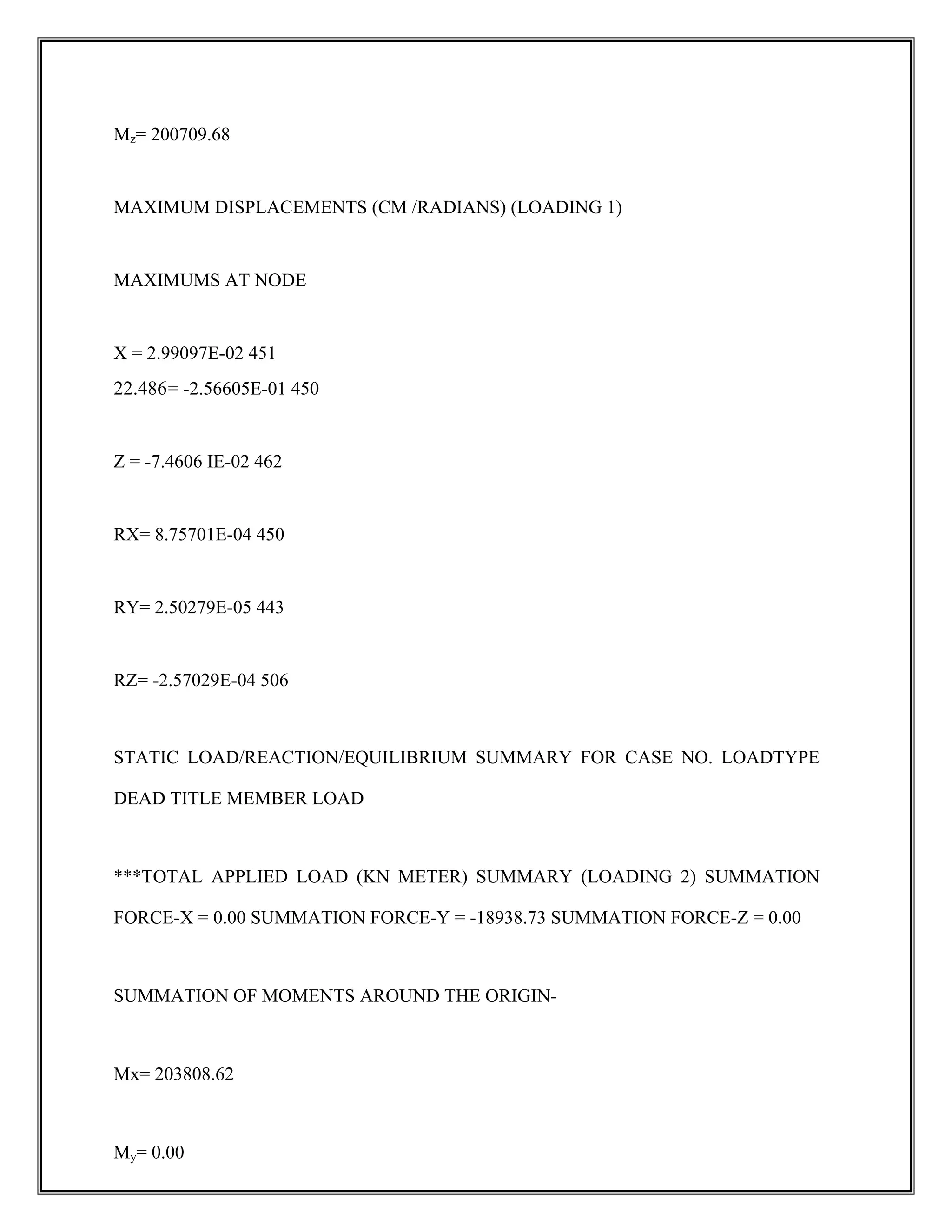
Mz= 200709.68
MAXIMUM DISPLACEMENTS(CM /RADIANS) (LOADING 1)
MAXIMUMS AT NODE
X = 2.99097E-02 451
22.486= -2.56605E-01 450
Z = -7.4606 IE-02 462
RX= 8.75701E-04 450
RY= 2.50279E-05 443
RZ= -2.57029E-04 506
STATIC LOAD/REACTION/EQUILIBRIUM SUMMARY FOR CASE NO. LOADTYPE
DEAD TITLE MEMBER LOAD
***TOTAL APPLIED LOAD (KN METER) SUMMARY (LOADING 2) SUMMATION
FORCE-X = 0.00 SUMMATION FORCE-Y = -18938.73 SUMMATION FORCE-Z = 0.00
SUMMATION OF MOMENTS AROUND THE ORIGIN-
Mx= 203808.62
My= 0.00
60.
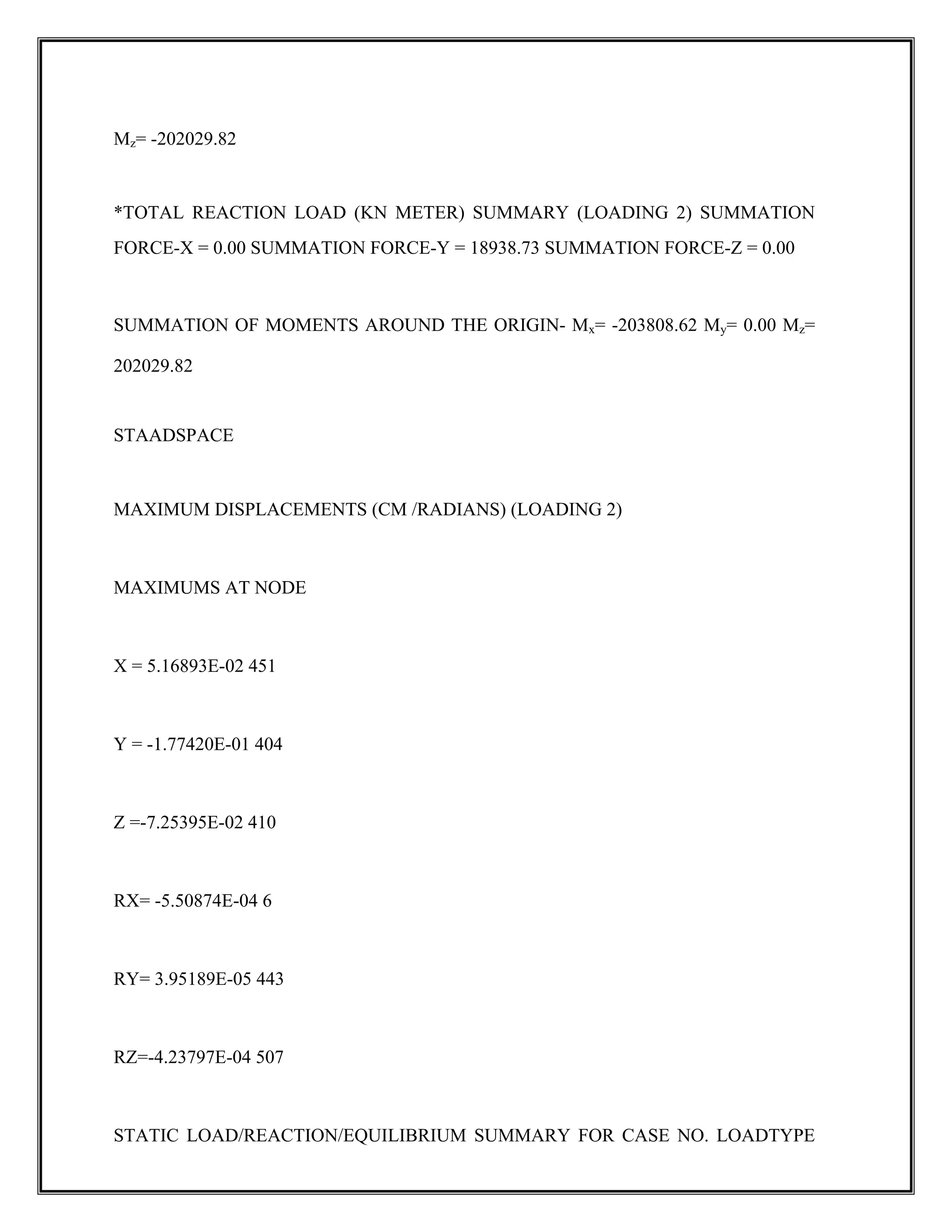
Mz= -202029.82
*TOTAL REACTIONLOAD (KN METER) SUMMARY (LOADING 2) SUMMATION
FORCE-X = 0.00 SUMMATION FORCE-Y = 18938.73 SUMMATION FORCE-Z = 0.00
SUMMATION OF MOMENTS AROUND THE ORIGIN- Mx= -203808.62 My= 0.00 Mz=
202029.82
STAADSPACE
MAXIMUM DISPLACEMENTS (CM /RADIANS) (LOADING 2)
MAXIMUMS AT NODE
X = 5.16893E-02 451
Y = -1.77420E-01 404
Z =-7.25395E-02 410
RX= -5.50874E-04 6
RY= 3.95189E-05 443
RZ=-4.23797E-04 507
STATIC LOAD/REACTION/EQUILIBRIUM SUMMARY FOR CASE NO. LOADTYPE
61.
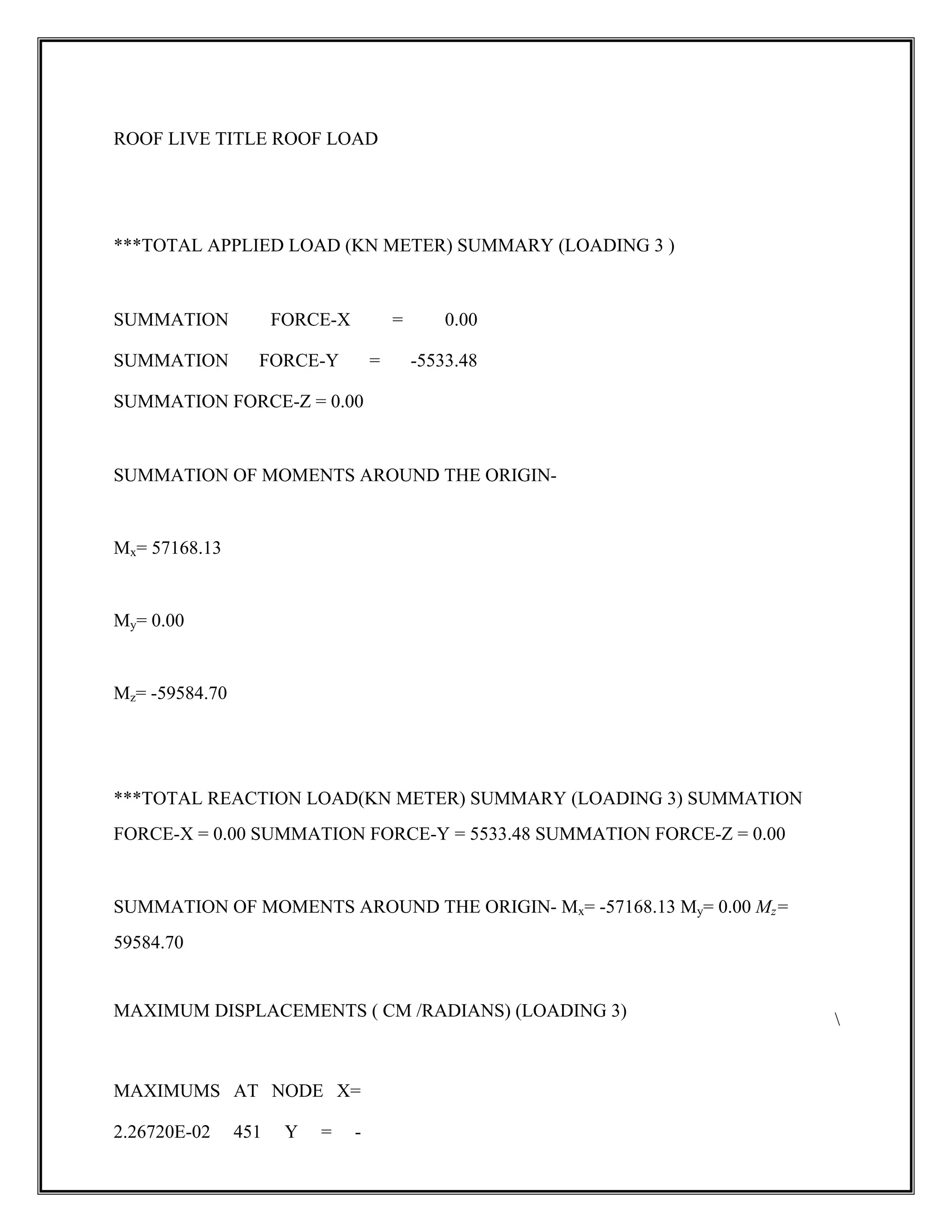
ROOF LIVE TITLEROOF LOAD
***TOTAL APPLIED LOAD (KN METER) SUMMARY (LOADING 3 )
SUMMATION FORCE-X = 0.00
SUMMATION FORCE-Y = -5533.48
SUMMATION FORCE-Z = 0.00
SUMMATION OF MOMENTS AROUND THE ORIGIN-
Mx= 57168.13
My= 0.00
Mz= -59584.70
***TOTAL REACTION LOAD(KN METER) SUMMARY (LOADING 3) SUMMATION
FORCE-X = 0.00 SUMMATION FORCE-Y = 5533.48 SUMMATION FORCE-Z = 0.00
SUMMATION OF MOMENTS AROUND THE ORIGIN- Mx= -57168.13 My= 0.00 Mz=
59584.70
MAXIMUM DISPLACEMENTS ( CM /RADIANS) (LOADING 3)
MAXIMUMS AT NODE X=
2.26720E-02 451 Y = -
62.
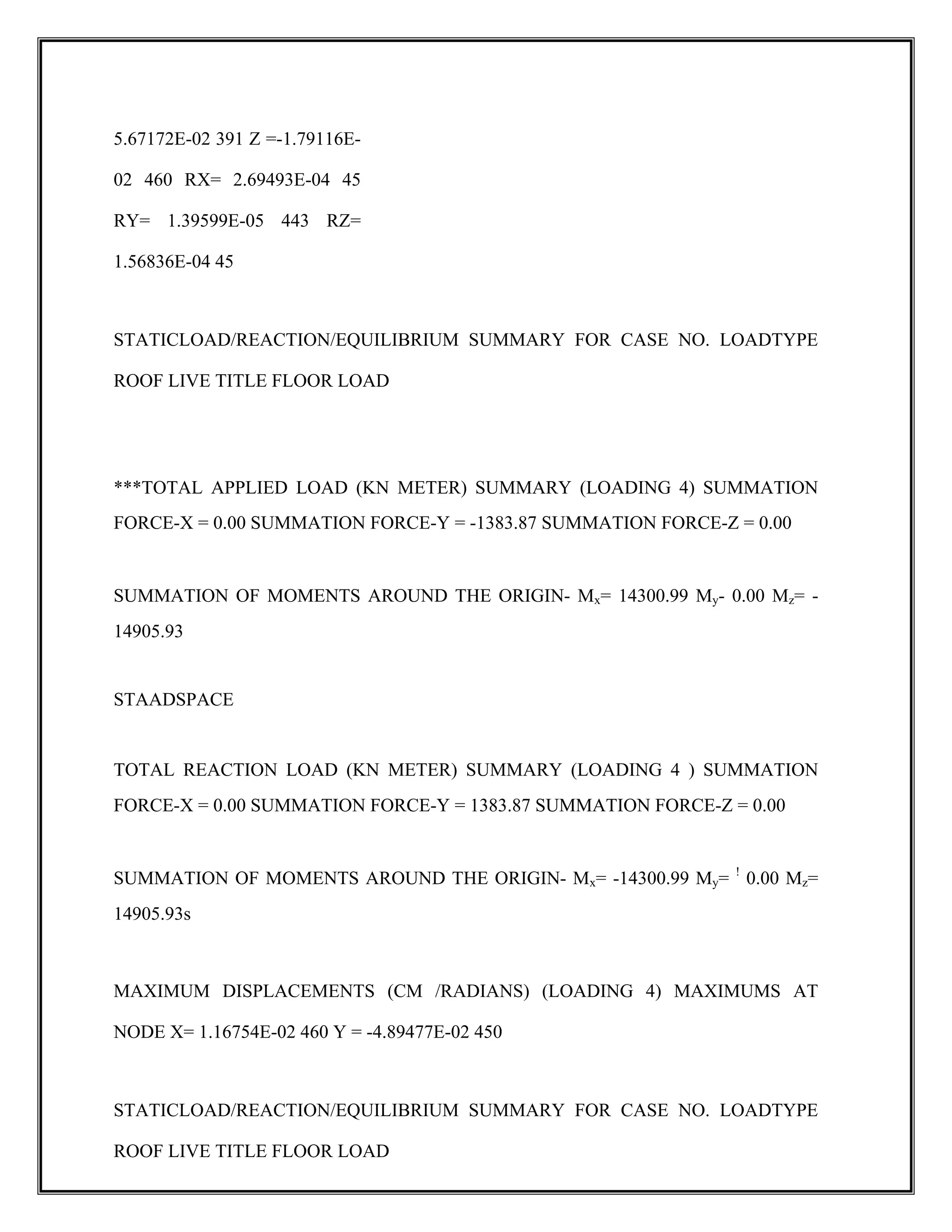
5.67172E-02 391 Z=-1.79116E-
02 460 RX= 2.69493E-04 45
RY= 1.39599E-05 443 RZ=
1.56836E-04 45
STATICLOAD/REACTION/EQUILIBRIUM SUMMARY FOR CASE NO. LOADTYPE
ROOF LIVE TITLE FLOOR LOAD
***TOTAL APPLIED LOAD (KN METER) SUMMARY (LOADING 4) SUMMATION
FORCE-X = 0.00 SUMMATION FORCE-Y = -1383.87 SUMMATION FORCE-Z = 0.00
SUMMATION OF MOMENTS AROUND THE ORIGIN- Mx= 14300.99 My- 0.00 Mz= -
14905.93
STAADSPACE
TOTAL REACTION LOAD (KN METER) SUMMARY (LOADING 4 ) SUMMATION
FORCE-X = 0.00 SUMMATION FORCE-Y = 1383.87 SUMMATION FORCE-Z = 0.00
SUMMATION OF MOMENTS AROUND THE ORIGIN- Mx= -14300.99 My= !
0.00 Mz=
14905.93s
MAXIMUM DISPLACEMENTS (CM /RADIANS) (LOADING 4) MAXIMUMS AT
NODE X= 1.16754E-02 460 Y = -4.89477E-02 450
STATICLOAD/REACTION/EQUILIBRIUM SUMMARY FOR CASE NO. LOADTYPE
ROOF LIVE TITLE FLOOR LOAD
63.
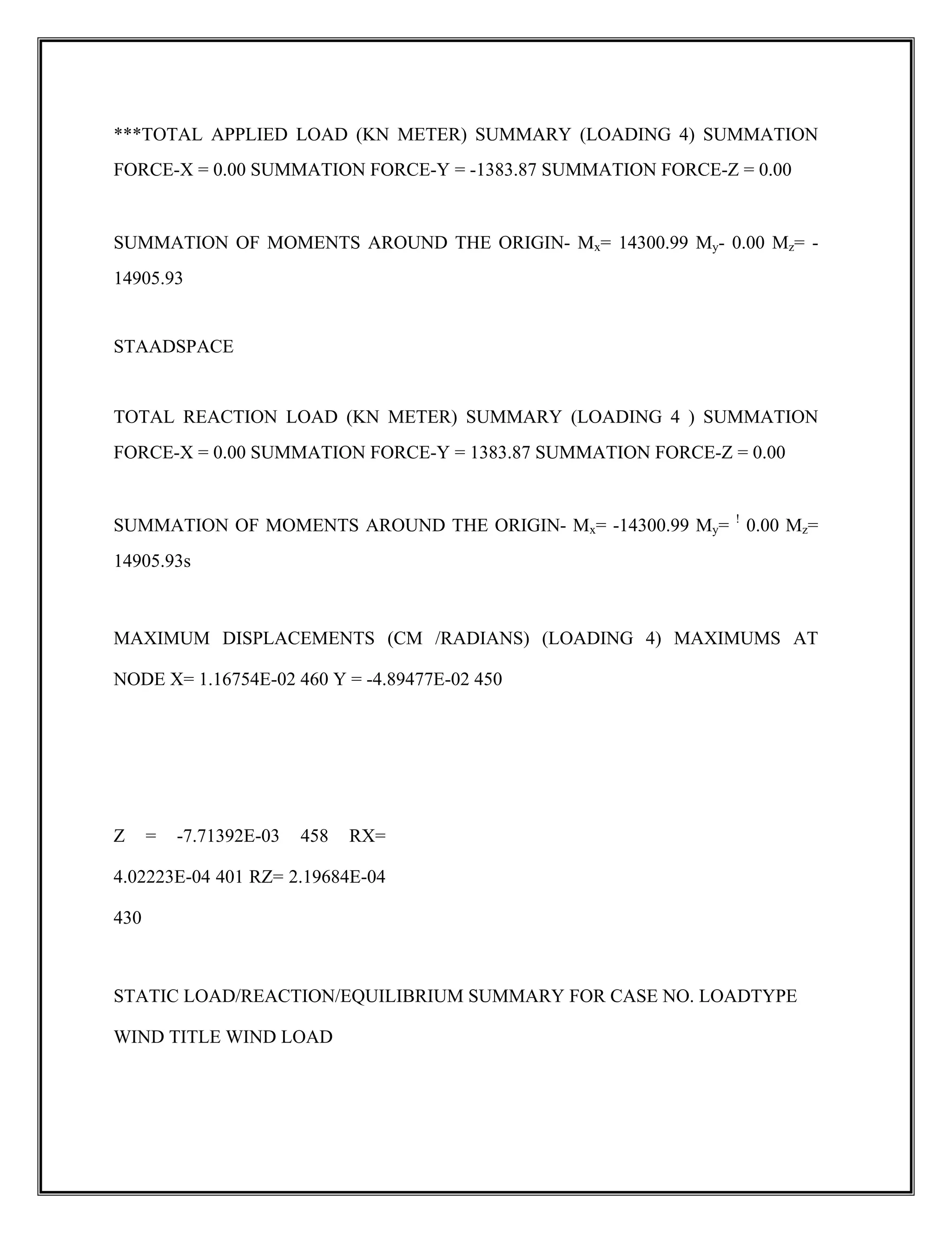
***TOTAL APPLIED LOAD(KN METER) SUMMARY (LOADING 4) SUMMATION
FORCE-X = 0.00 SUMMATION FORCE-Y = -1383.87 SUMMATION FORCE-Z = 0.00
SUMMATION OF MOMENTS AROUND THE ORIGIN- Mx= 14300.99 My- 0.00 Mz= -
14905.93
STAADSPACE
TOTAL REACTION LOAD (KN METER) SUMMARY (LOADING 4 ) SUMMATION
FORCE-X = 0.00 SUMMATION FORCE-Y = 1383.87 SUMMATION FORCE-Z = 0.00
SUMMATION OF MOMENTS AROUND THE ORIGIN- Mx= -14300.99 My= !
0.00 Mz=
14905.93s
MAXIMUM DISPLACEMENTS (CM /RADIANS) (LOADING 4) MAXIMUMS AT
NODE X= 1.16754E-02 460 Y = -4.89477E-02 450
Z = -7.71392E-03 458 RX=
4.02223E-04 401 RZ= 2.19684E-04
430
STATIC LOAD/REACTION/EQUILIBRIUM SUMMARY FOR CASE NO. LOADTYPE
WIND TITLE WIND LOAD
64.
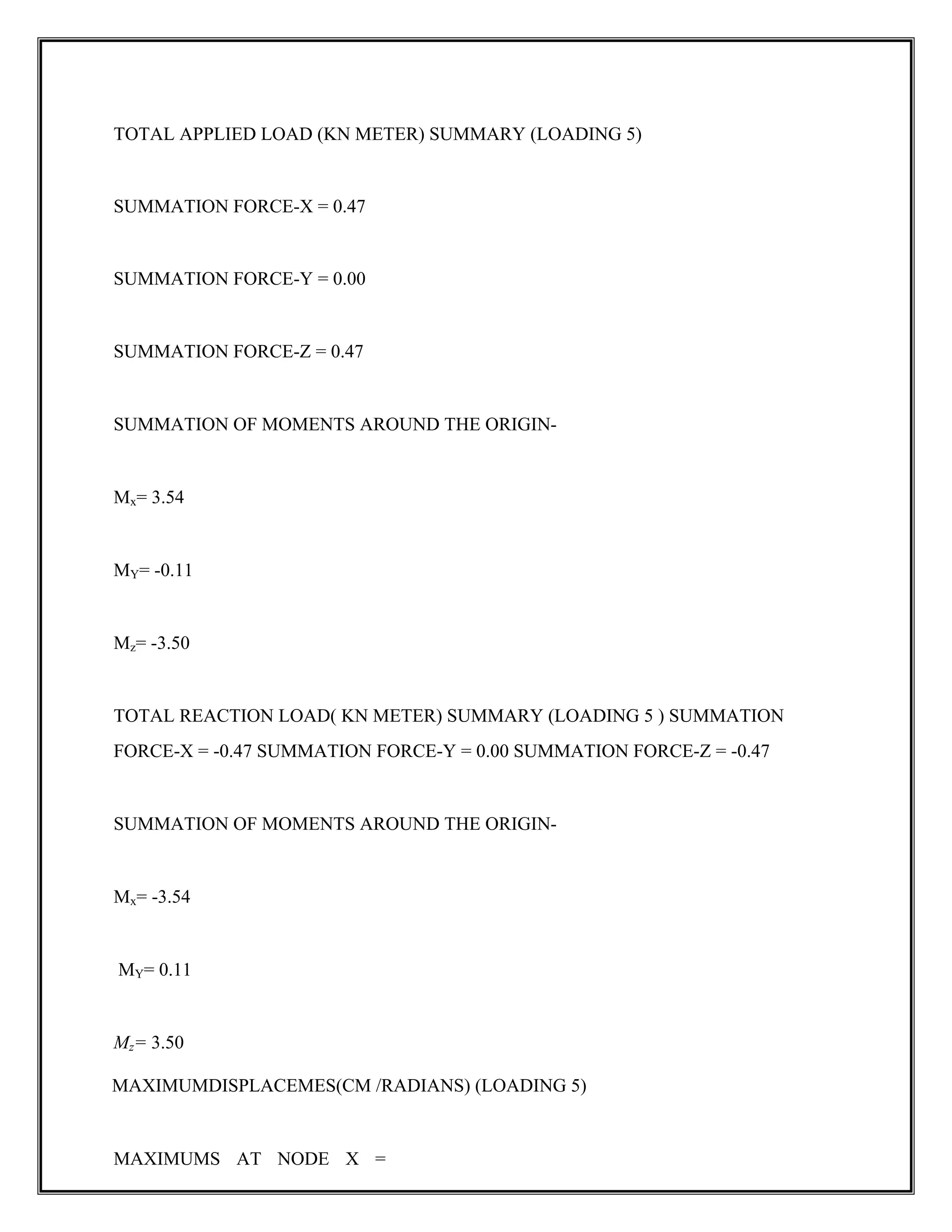
TOTAL APPLIED LOAD(KN METER) SUMMARY (LOADING 5)
SUMMATION FORCE-X = 0.47
SUMMATION FORCE-Y = 0.00
SUMMATION FORCE-Z = 0.47
SUMMATION OF MOMENTS AROUND THE ORIGIN-
Mx= 3.54
MY= -0.11
Mz= -3.50
TOTAL REACTION LOAD( KN METER) SUMMARY (LOADING 5 ) SUMMATION
FORCE-X = -0.47 SUMMATION FORCE-Y = 0.00 SUMMATION FORCE-Z = -0.47
SUMMATION OF MOMENTS AROUND THE ORIGIN-
Mx= -3.54
MY= 0.11
Mz= 3.50
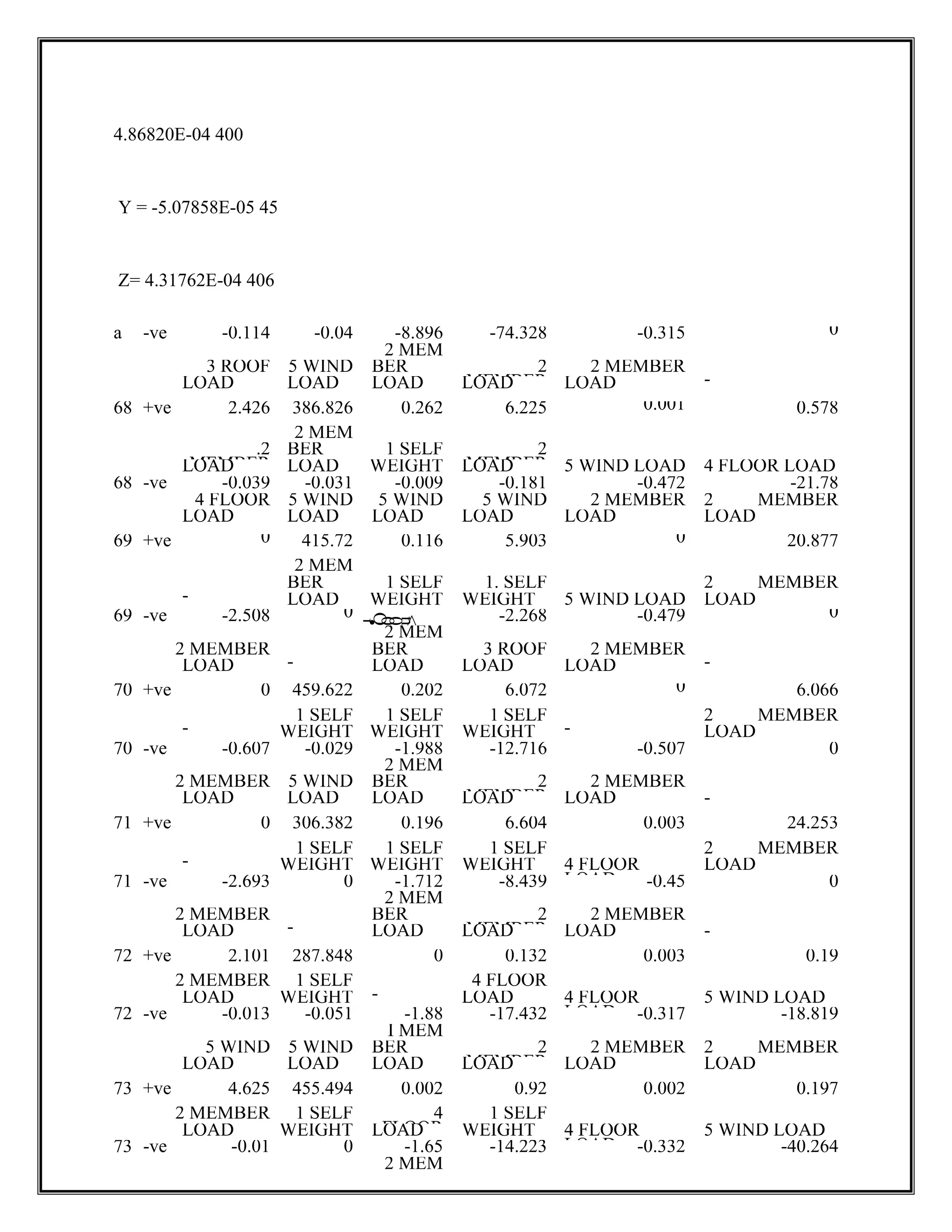
MAXIMUMDISPLACEMES(CM /RADIANS) (LOADING 5)
MAXIMUMS AT NODE X =
65.
4.86820E-04 400
Y =-5.07858E-05 45
Z= 4.31762E-04 406
a -ve -0.114 -0.04 -8.896 -74.328 -0.315 0
2 MEM
3 ROOF 5 WIND BER 2
MEMBER
2 MEMBER
LOAD LOAD LOAD LOAD LOAD -
68 +ve 2.426 386.826 0.262 6.225 0.001 0.578
2 MEM
.2
MEMBER
BER 1 SELF 2
MEMBER
LOAD LOAD WEIGHT LOAD 5 WIND LOAD 4 FLOOR LOAD
68 -ve -0.039 -0.031 -0.009 -0.181 -0.472 -21.78
4 FLOOR 5 WIND 5 WIND 5 WIND 2 MEMBER 2 MEMBER
LOAD LOAD LOAD LOAD LOAD LOAD
69 +ve 0 415.72 0.116 5.903 0 20.877
2 MEM
BER 1 SELF 1. SELF 2 MEMBER
- LOAD WEIGHT WEIGHT 5 WIND LOAD LOAD
69 -ve -2.508 0
1
•
O
0
0
u
-2.268 -0.479 0
2 MEM
2 MEMBER BER 3 ROOF 2 MEMBER
LOAD - LOAD LOAD LOAD -
70 +ve 0 459.622 0.202 6.072 0 6.066
1 SELF 1 SELF 1 SELF 2 MEMBER
- WEIGHT WEIGHT WEIGHT - LOAD
70 -ve -0.607 -0.029 -1.988 -12.716 -0.507 0
2 MEM
2 MEMBER 5 WIND BER 2
MEMBER
2 MEMBER
LOAD LOAD LOAD LOAD LOAD -
71 +ve 0 306.382 0.196 6.604 0.003 24.253
1 SELF 1 SELF 1 SELF 2 MEMBER
- WEIGHT WEIGHT WEIGHT 4 FLOOR
LOAD
LOAD
71 -ve -2.693 0 -1.712 -8.439 -0.45 0
2 MEM
2 MEMBER BER 2
MEMBER
2 MEMBER
LOAD - LOAD LOAD LOAD -
72 +ve 2.101 287.848 0 0.132 0.003 0.19
2 MEMBER 1 SELF 4 FLOOR
LOAD WEIGHT - LOAD 4 FLOOR
LOAD
5 WIND LOAD
72 -ve -0.013 -0.051 -1.88 -17.432 -0.317 -18.819
I MEM
5 WIND 5 WIND BER 2
MEMBER
2 MEMBER 2 MEMBER
LOAD LOAD LOAD LOAD LOAD LOAD
73 +ve 4.625 455.494 0.002 0.92 0.002 0.197
2 MEMBER 1 SELF 4
FLOOR
1 SELF
LOAD WEIGHT LOAD WEIGHT 4 FLOOR
LOAD
5 WIND LOAD
73 -ve -0.01 0 -1.65 -14.223 -0.332 -40.264
2 MEM
66.
59
5 WIND BER2
MEMBER
2 MEMBER 2 MEMBER
LOAD - LOAD LOAD LOAD LOAD
74 +ve 0 494.049 0.011 2.157 0.067 55.117
1 SELF 4 FLOOR 1 SELF 2 MEMBER
- WEIGHT LOAD WEIGHT 1 SELF
WEIGHT
LOAD
74 -ve -6.343 -0.061 -1.438 -10.431 -0.38 0
2 MEM
2 MEMBER 5 WIND BER 2
MEMBER
2 MEMBER
Design of footingunder column ’K’
Factored load on column =1090.1KN
Size of column -230x450mm
SBC of soil (Hard Morram) is 300 per code for working load
Self weight of footing =10% of =
=0.1x1090.1=09.01KN
Area footing =
=[1090.1=109.01]/300=4m ²
Provide a square footing of size =1.5m x 2.7m
Net upward pressure intensity =1090.1/[1.5 x2.7] = 269.14 KN/m ²
Design of flexure:
Critical section occurs at the face of column
L= (2.7-0.45) / 2= 1.125
= = (269.14 x 1.5 x 1.125 x 1.125) = 510.92 KN M
Lu = (1.5-0.23) / 2 = 0.635m
= (1.5 x 269.14 x 0.635 x 0.635) / 2 = 81.39KN.M
Depth of footing:
D= [510.95 x 10^6/2.3 x 1000] ^0.5=430mm
93.
Increase depth toaccount for shear
Taking d = 700mm
Slope height = 300
Flat height = 300mm
Check for One –Way shear
Critical shear force occurs at a distance of `d’ from face of the column
X = [2.7 -4.45]/2-0.7 = 0.425
Shear force V = 0.425 x 1.5 x 269.4 = 257.6 KN
Nominal shear stress
= 257600/ [1500 x 408] =0.42 N/mm²
For 0.46% of steel = from IS456:2000 table- 19
Permissible shear stress ( ) = K where K=1
= 1 x 0.47 = 0.47N/mm²
Footing is safe in shear
Check for Two- way shear
Critical shear occurs at a distance of d/2 from face of the column
Nominal shear stress =
Shear force = 1090.1-[1.15 x 0.93 x 269.1] = 802.29 KN
94.
= 802290/ [2(1.15=0.93)x 1000 x 530] = 0.36 N/mm^2
Permissible shear stress τc
1
= k τc
Where K=0.5+β = 0.5 + (0.23/0.45) = 1.111 from IS456.2000
τc
1
=0.25 √fck= 0.25√20=1.11N/mm²
τc
1
k τcÆ Safe
Calculations of Area of steel
x = 0.5 [1- ]bd
= 2534.457 mm^2
Using 18 mm bars @ 90 mm c/c
= 403.35 mm^2
Using 10 mm ø bars
Spacing of bar = 78.5 x 1000/ 403.3= 190mm c/c
Provide300mmthickness at the edgeof footing
95.
CHAPTER 11
STAIR CASE
DESIGNOF STAIR CASE
Vertical Distance between floors = 3000mm
Providing Dog-legged stair case
General arrangements
Width of landing =250mm
96.
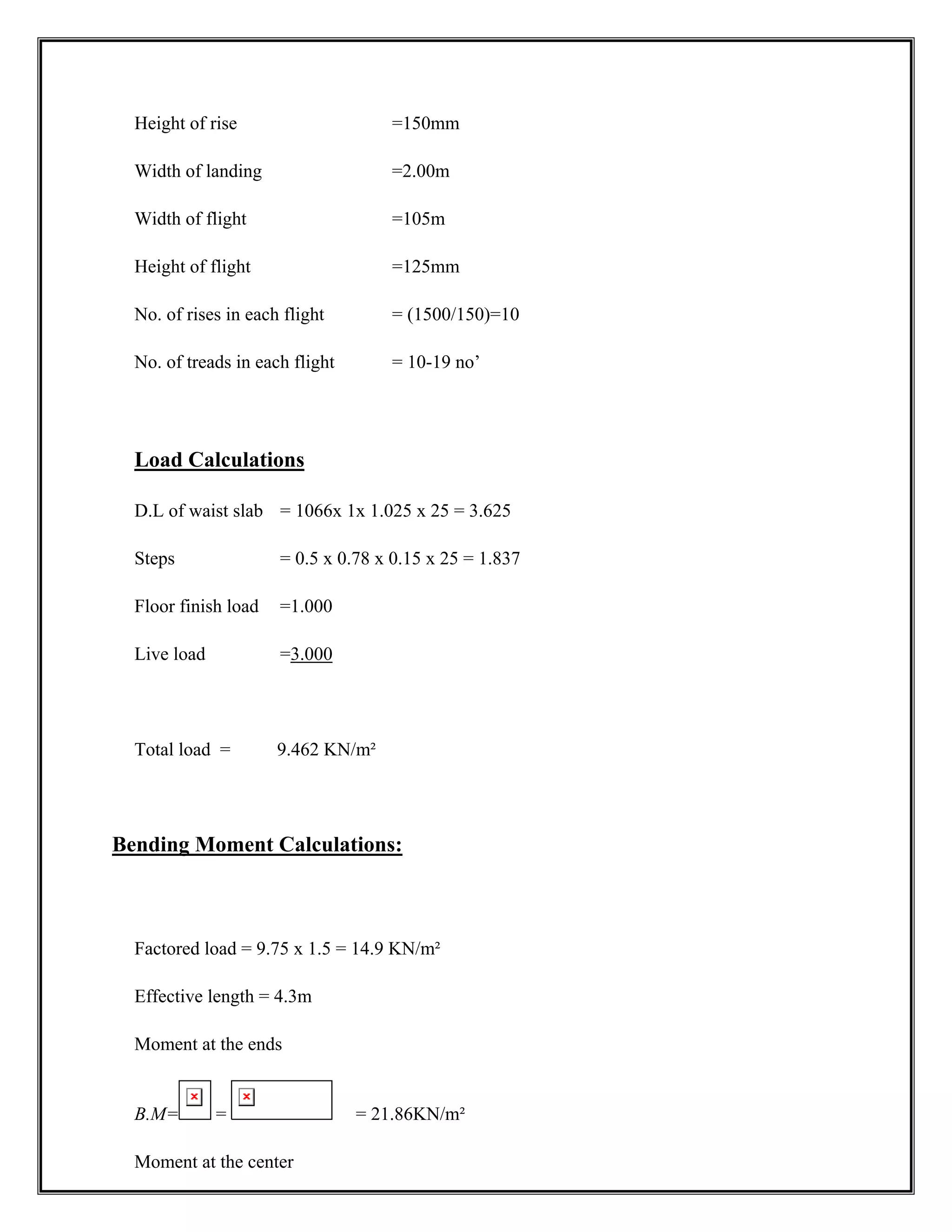
Height of rise=150mm
Width of landing =2.00m
Width of flight =105m
Height of flight =125mm
No. of rises in each flight = (1500/150)=10
No. of treads in each flight = 10-19 no’
Load Calculations
D.L of waist slab = 1066x 1x 1.025 x 25 = 3.625
Steps = 0.5 x 0.78 x 0.15 x 25 = 1.837
Floor finish load =1.000
Live load =3.000
Total load = 9.462 KN/m²
Bending Moment Calculations:
Factored load = 9.75 x 1.5 = 14.9 KN/m²
Effective length = 4.3m
Moment at the ends
B.M= = = 21.86KN/m²
Moment at the center
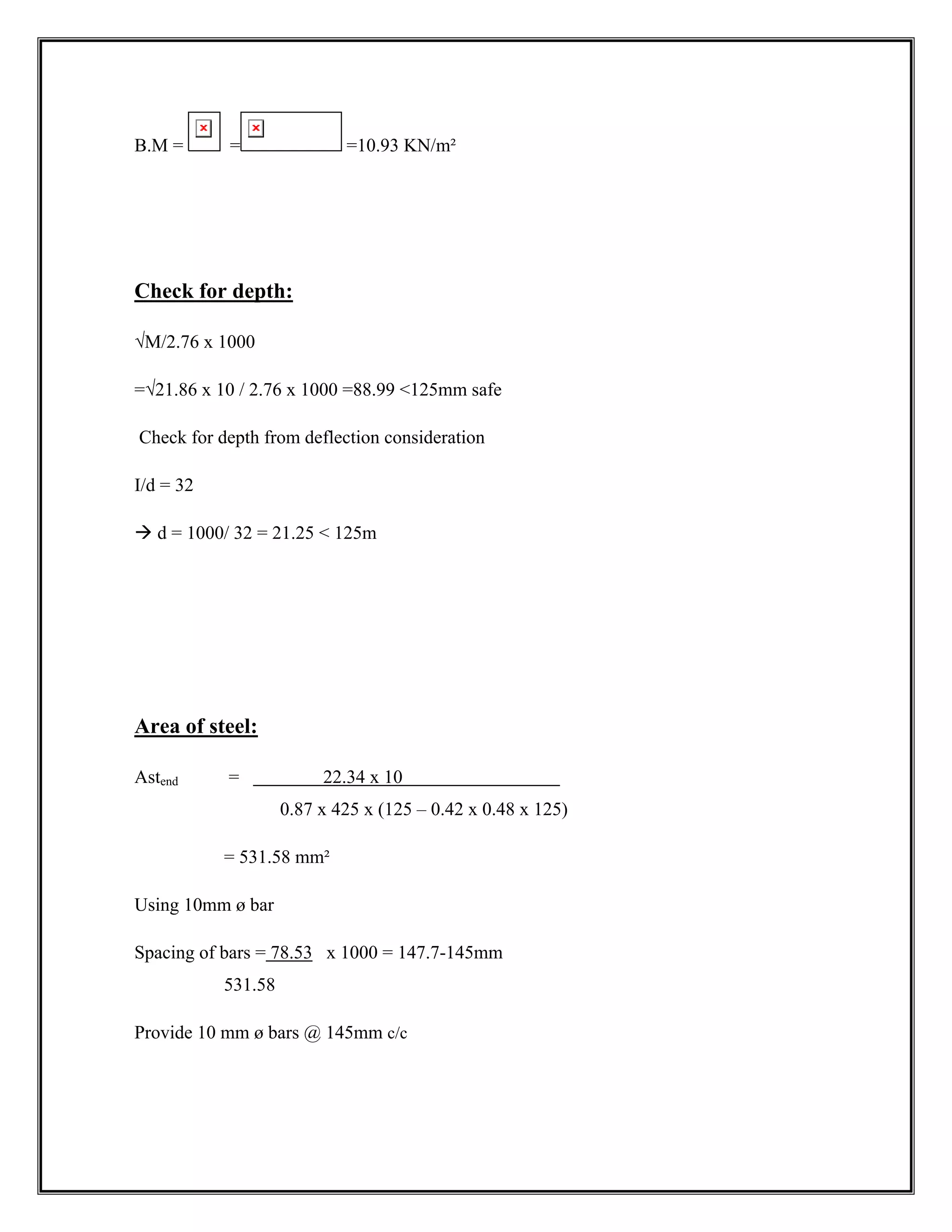
97.
B.M = ==10.93 KN/m²
Check for depth:
√M/2.76 x 1000
=√21.86 x 10 / 2.76 x 1000 =88.99 125mm safe
Check for depth from deflection consideration
I/d = 32
Æ d = 1000/ 32 = 21.25 125m
Area of steel:
Astend = 22.34 x 10
0.87 x 425 x (125 – 0.42 x 0.48 x 125)
= 531.58 mm²
Using 10mm ø bar
Spacing of bars = 78.53 x 1000 = 147.7-145mm
531.58
Provide 10 mm ø bars @ 145mm c/c
98.
Distribution Reinforcement:
=0.15 B.D
=0.15x 1000 x 125 = 187.5 mm²
100
Using 6mm ø bars @ 150 mm c/c
CONCLUSIONS
Staad Pro software has become more and more critical in the analysis of engineering and
scientific problems. Much of the reason for this change from manual methods has been the
advancement of computer techniques development by the research community and in
particular universities.
As technology and engineering adoptions are advertising new methodology of
interlinking and completing the industries via computer applications are created with a
similar improvement in hardware capacities. This is turn facilities the implementations of
more effective and professional engineering software. As the applications adventure in
functionality, one can hope that they will be more affordable to promote their widespread
usage amongst civil engineering at a global scale.
99.
Taking into accountthe technological advance, this project has been dealt with
using the latest design software.
References
1. Is: 456-2000 design for reinforced.
2. IS: 875(part – 3)- 1987 code of practice for design loads for building and structures.
3. SP: 16 designs for reinforce concrete.
4. AUTO CAD STAAD PRO- 2007
5. Reinforcement concrete design by N.KRISHNA RAJU R.N.PRANESH
6. Design of reinforced concrete structure by S.RAMAMURTHAM.


![= 0.047 x 8.81 x = 4.69 KN-m
(+ve) B.M at mid span
= w
= 0.035 x 8.81 x = 3.69 KN-m
Design Bending Moment = 8.12 KN-m
Check for effective depth
d =
= = 54.24<100 mm
Calculation of Area of steel
Minimum as per IS 456:2000
= ÎA =
A = = 204.81
(-ve) Reinforced along continuous support of short span
=0.5 [1- ] bd
=0.5 [1- ] 1000 x 100
= 236.63
Spacing of 8 mm Ø bars](https://image.slidesharecdn.com/projectreportonmultistoriedbuilding-expertcivil-210703063903/75/Project-report-on-multi-storied-building-expertcivil-36-2048.jpg)
![S= x 1000 Î x 1000 = 212.39 = 210 mm c/c
Spacing should be letter of
1. 3d = 3 x 95 = 285 mm
2. 300 mm
3. Spacing calculated = 210 mm
Provide 8 mm Ø bars @ 210 mm c/c
Bent alternate bars at from the support @
Provide extra bars (top) at 400 mm c/c from the support.
=0.5 [1- ] 1000 x 100
= 141.31
Provide = 204.81
Provide 8 mm Ø bars @ 245 mm c/c
Check for shear
Shear force = = = 15.24 x N
Nominal shear stress ( ) =](https://image.slidesharecdn.com/projectreportonmultistoriedbuilding-expertcivil-210703063903/75/Project-report-on-multi-storied-building-expertcivil-37-2048.jpg)
![B.M = = = 15.99 KN
Depth from moment consideration
d =
d = = 76.11 mm
Depth from stiffness consideration
D = = 119.0 mm 120 mm
d = 120-20 = 100 mm.
Calculation of area of steel
=0.5 [1- ] 1000 x 100
= 382.24 m
Spacing of 8 mm Ø bars
x 1000 = 131.48 130 mm c/c
Provide 8 mm Ø @ 120 mm c/c
Transverse reinforcement
Asty = 0.15% of BD](https://image.slidesharecdn.com/projectreportonmultistoriedbuilding-expertcivil-210703063903/75/Project-report-on-multi-storied-building-expertcivil-39-2048.jpg)


![Design of footing under column ’K’
Factored load on column =1090.1KN
Size of column -230x450mm
SBC of soil (Hard Morram) is 300 per code for working load
Self weight of footing =10% of =
=0.1x1090.1=09.01KN
Area footing =
=[1090.1=109.01]/300=4m ²
Provide a square footing of size =1.5m x 2.7m
Net upward pressure intensity =1090.1/[1.5 x2.7] = 269.14 KN/m ²
Design of flexure:
Critical section occurs at the face of column
L= (2.7-0.45) / 2= 1.125
= = (269.14 x 1.5 x 1.125 x 1.125) = 510.92 KN M
Lu = (1.5-0.23) / 2 = 0.635m
= (1.5 x 269.14 x 0.635 x 0.635) / 2 = 81.39KN.M
Depth of footing:
D= [510.95 x 10^6/2.3 x 1000] ^0.5=430mm](https://image.slidesharecdn.com/projectreportonmultistoriedbuilding-expertcivil-210703063903/75/Project-report-on-multi-storied-building-expertcivil-92-2048.jpg)
![Increase depth to account for shear
Taking d = 700mm
Slope height = 300
Flat height = 300mm
Check for One –Way shear
Critical shear force occurs at a distance of `d’ from face of the column
X = [2.7 -4.45]/2-0.7 = 0.425
Shear force V = 0.425 x 1.5 x 269.4 = 257.6 KN
Nominal shear stress
= 257600/ [1500 x 408] =0.42 N/mm²
For 0.46% of steel = from IS456:2000 table- 19
Permissible shear stress ( ) = K where K=1
= 1 x 0.47 = 0.47N/mm²
Footing is safe in shear
Check for Two- way shear
Critical shear occurs at a distance of d/2 from face of the column
Nominal shear stress =
Shear force = 1090.1-[1.15 x 0.93 x 269.1] = 802.29 KN](https://image.slidesharecdn.com/projectreportonmultistoriedbuilding-expertcivil-210703063903/75/Project-report-on-multi-storied-building-expertcivil-93-2048.jpg)
![= 802290/ [2(1.15=0.93) x 1000 x 530] = 0.36 N/mm^2
Permissible shear stress τc
1
= k τc
Where K=0.5+β = 0.5 + (0.23/0.45) = 1.111 from IS456.2000
τc
1
=0.25 √fck= 0.25√20=1.11N/mm²
τc
1
k τcÆ Safe
Calculations of Area of steel
x = 0.5 [1- ]bd
= 2534.457 mm^2
Using 18 mm bars @ 90 mm c/c
= 403.35 mm^2
Using 10 mm ø bars
Spacing of bar = 78.5 x 1000/ 403.3= 190mm c/c
Provide300mmthickness at the edgeof footing](https://image.slidesharecdn.com/projectreportonmultistoriedbuilding-expertcivil-210703063903/75/Project-report-on-multi-storied-building-expertcivil-94-2048.jpg)